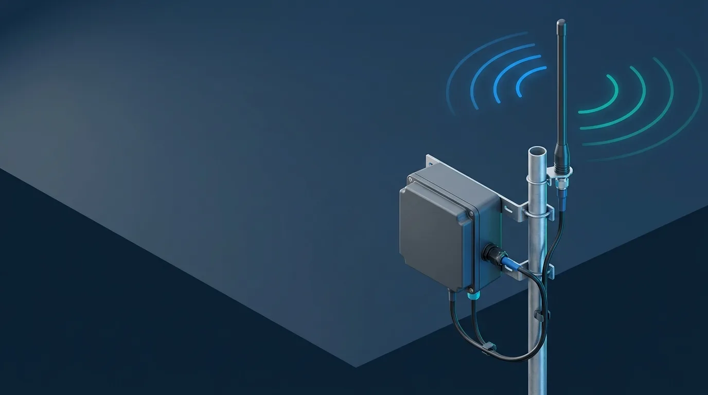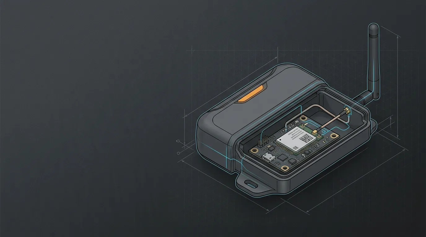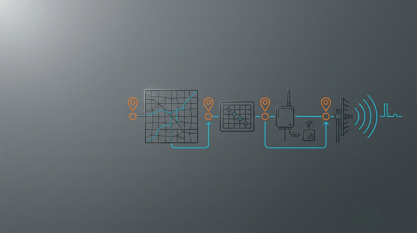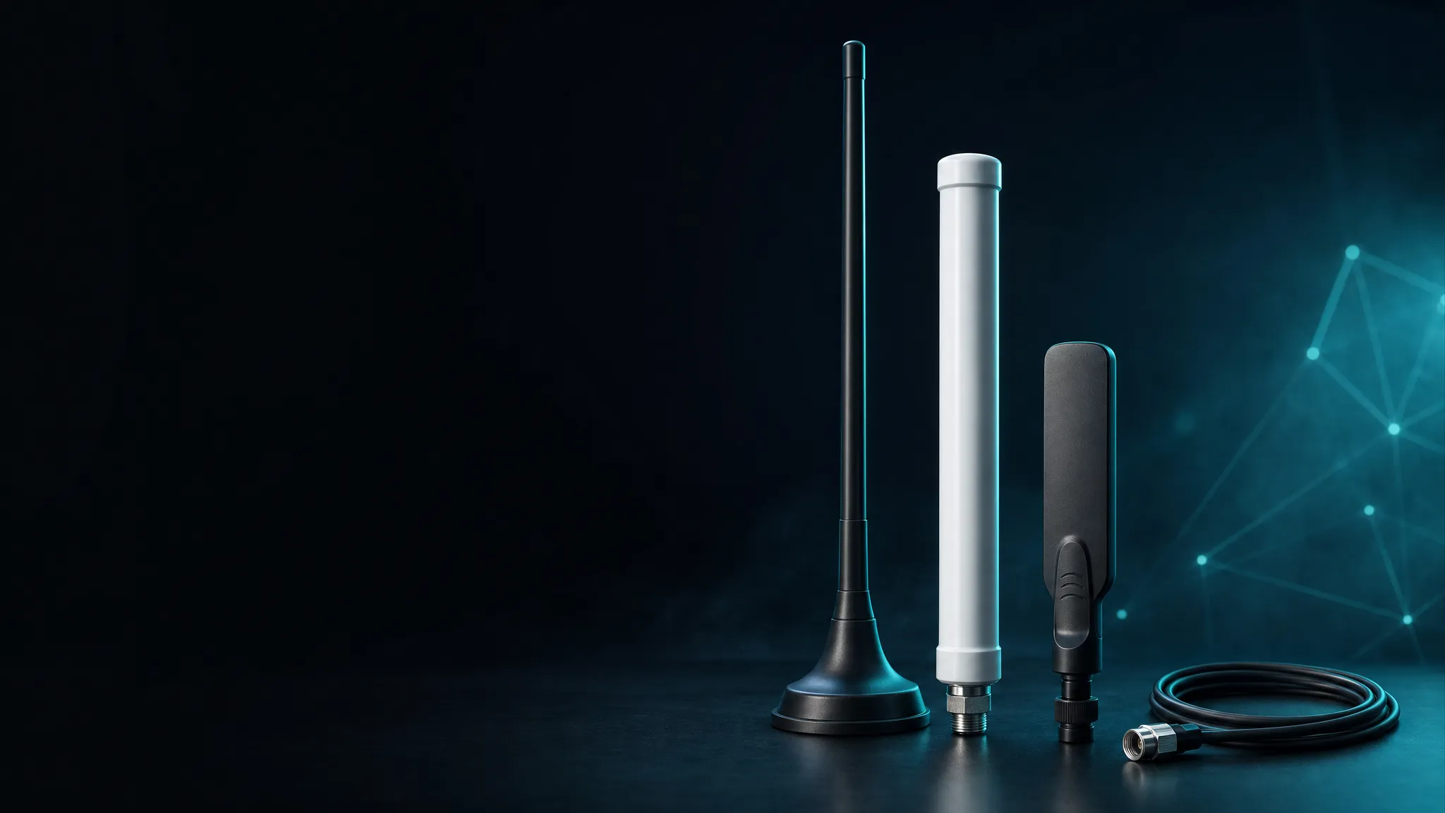
An IoT antenna is chosen by radio first, form factor second. LoRa at 433 MHz needs a long whip tuned to a ~69 cm wavelength; a 4G tracker needs a multi-band antenna covering 824–960 and 1710–2700 MHz; a Wi-Fi 6E gateway needs an external antenna that spans 2.4, 5 and 6 GHz. Get the band right and everything else — gain, mounting, cable, IP rating — is a set of trade-offs you can evaluate in one afternoon. Get the band wrong and no antenna upgrade will fix it.
This is the hub of the IoT & M2M antenna series: a radio-first framework for IoT antenna selection, the specs that actually move your link, and an 8-point RFQ checklist you can send to any manufacturer. Each section links to a focused deep dive (433 MHz, 4G, 5G, Wi-Fi, link budgets, form factors, cables, environmental specs), so you read the framework here and drill into only the parts that apply to your product.
The one decision that drives everything: which radio is on the device
Every antenna spec traces back to the radio. The frequency decides the physical size of the antenna, the bandwidth decides how many bands it can cover, and the protocol decides how much range you need. Start by writing down the radio, the regional bands it uses, and the deployment environment — then the antenna category mostly picks itself.
| Radio / protocol | Typical bands | What it demands from the antenna | Range character |
|---|---|---|---|
| LoRa / ISM sub-GHz | 433 MHz (EU ISM), 868 MHz (EU), 902–928 MHz (US) | Single-band, narrowband, often a whip or collinear; large antenna (quarter-wave ≈ 17 cm at 433 MHz) | Long, obstacle-tolerant, low data rate |
| 4G LTE (Cat-1/4, LTE-M) | 700–960 / 1710–2700 MHz | Multi-band coverage, often wideband omni; external antenna beats internal in enclosures | Wide-area cellular, metres to km depending on coverage |
| 5G FR1 (sub-6 GHz) | 700–960, 1710–2700, 3300–5000, 5150–5850 MHz | Wideband multi-band; form factor must fit gateways, vehicles or fixed wireless terminals | High throughput, shorter range, placement-sensitive |
| Wi-Fi 6E | 2.4 / 5 / 6 GHz | Dual- or tri-band (up to 1350 MHz of bandwidth), compact external or internal | Short-range, high rate, congested spectrum |
| Regional / private bands | 470–510, 1447–1805, 301–340, 3300–3400 MHz | Band-specific tuning; fiberglass omni for base stations | Deployment-specific |
The pattern to notice: sub-GHz LoRa buys range with wavelength, and pays with antenna size — a gain-loaded 433 MHz whip can run 89 cm. Cellular buys coverage with licensed spectrum and multi-band antennas that must match the regional bands of every market you ship to. Wi-Fi buys throughput and pays with range and congestion. The trade-offs are exactly the ones Siretta’s band-by-band guide lays out below 6 GHz; the Wi-Fi 6E bands themselves come from the IEEE 802.11 working group standards family. Together they explain why “4G” or “Wi-Fi” printed on a datasheet is never enough — you need the exact bands.
Regionality is where most selection mistakes happen. LoRaWAN uses 433 or 868 MHz in Europe and 902–928 MHz in North America; a 4G antenna for Europe must cover bands like B1/B3/B7/B20 while a US tracker needs B2/B4/B5/B12/B13; 5G adds n77/n78/n79 for mid-band and n1/n3/n28 for low-band. The LoRa Alliance’s LoRaWAN specification defines the network layer, and Semtech’s LoRa platform — with more than 500 million LoRa end nodes deployed as of March 2026 — is where the sub-GHz ecosystem converges. But no standard will save an antenna tuned for the wrong region, so confirm the exact band list with your module vendor before you spec the antenna.
Deep dives:
- 433 MHz antenna guide: range, gain and mounting for LoRa (published)
- 4G LTE external antennas: what actually matters for IoT
- 5G antennas for IoT and fixed wireless
- Wi-Fi 6E external antennas: 2.4 / 5 / 6 GHz explained
- LoRa vs 4G vs 5G for IoT: connectivity and antenna implications
What the antenna actually does to the link
Range comes from a budget, not from a single spec. The usable link is the radio’s transmit power, plus antenna gains, minus cable and connector losses, minus the path loss of the environment, compared against the receiver’s sensitivity — with margin left over. Change one line of that budget and you see why antenna selection is a system decision.
Three numbers anchor the intuition:
| What 3 dB is worth | Free-space range effect |
|---|---|
| +3 dBi antenna gain | 1.41× range (6 dBi → 2×) |
| 3 dB less cable loss | 1.41× range |
| +3 dB receiver sensitivity | 1.41× range |
The same arithmetic explains why sub-GHz beats 2.4 GHz: path loss at 433 MHz over 1 km is ~85 dB versus ~100 dB at 2.4 GHz — a ~15 dB gap, roughly five times the free-space reach at equal power and gain. And cable loss is real money: RG174 loses ~0.5 dB per metre at 433 MHz, RG58A/U about half that, so a 3-metre run silently eats 1.5 dB of the budget before the signal reaches the radio.
The practical consequence: gain is the least reliable spec to chase, because placement swamps it. An antenna with 5.5 dBi of gain bolted against a metal surface, or a PCB antenna inside a metal enclosure, can lose 10–20 dB to detuning and absorption — more than any gain figure on the datasheet. Height is also range: raising an antenna from 1 m to 2 m clears the first Fresnel zone and typically gains more than an antenna upgrade.
A concrete example keeps the numbers honest. A 433 MHz LoRa base at +14 dBm, with a 2 dBi whip, 0.5 dB of cable loss, a -130 dBm receiver and 20 dB of margin, has a 125.5 dB budget — versus roughly 85 dB of free-space loss at 1 km, so it clears a kilometre with margin to spare, limited in the field by terrain and foliage rather than radio math. Swap to a 5.5 dBi magnetic-mount whip and a shorter cable, and the budget climbs to about 129.5 dB — a ~1.6× free-space range gain, or the same range with 4 dB more margin against rain and interference.
Work through your own numbers with the link-budget calculator, or read the full treatment in IoT antenna range: gain, cable loss and link budget.
IoT antenna form factors: whip, magnetic mount, fiberglass omni and paddle
Once the band is fixed, the form factor decides where the antenna can live and how well it radiates there. Four shapes cover nearly every IoT deployment:
| Form factor | Best for | Typical gain | Watch out for |
|---|---|---|---|
| Whip (flexible, straight, hinged, paddle) | Devices, terminals, routers, handheld bases | 0–3 dBi, band-specific | Needs clearance from metal; VSWR at band edges |
| Magnetic mount | Vehicles, temporary field installs, test setups | 2–5.5 dBi with the mount as ground plane | Height, wind rating, connector (SL16 vs SMA) |
| Fiberglass omni | Outdoor base stations, masts, fixed infrastructure | 3–5 dBi, 360° pattern | Size, N-type connectors, lightning grounding |
| PCB / chip (internal) | Compact consumer and OEM devices | -5 to +1 dBi typical | Short range, detuning near metal, enclosure dependence |
The IoT For All guide to IoT antenna types walks the internal side of this trade — trace, FPC, SMT and helix antennas and their integration constraints. The external side is where range, reliability and serviceability live, and it is where a manufacturer’s product line earns its keep.
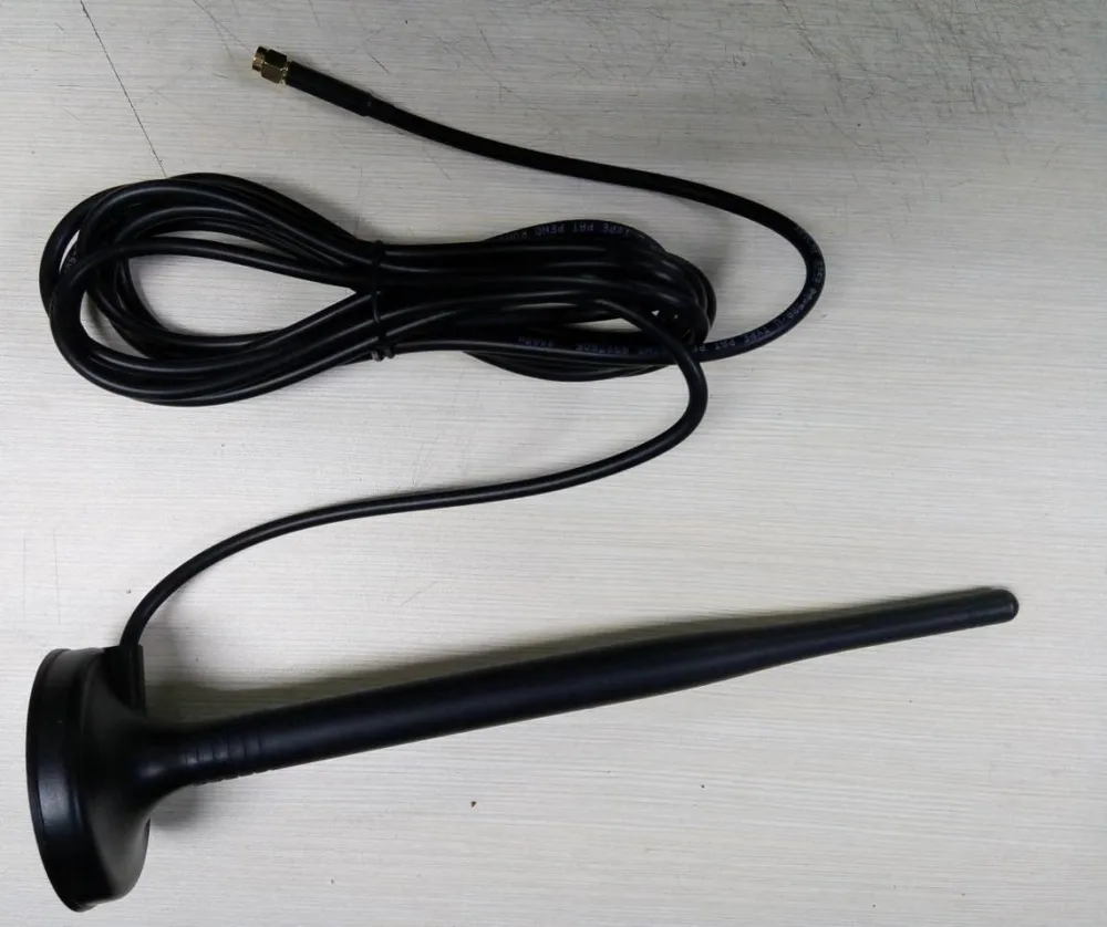
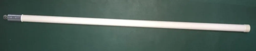
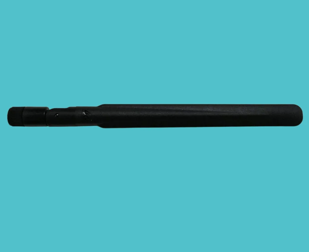
For vehicles and temporary sites, a magnetic mount doubles as the ground plane and can be moved in minutes — the LGW-5G-JBXP01 packs 824–5800 MHz coverage, salt-spray and thermal-shock qualification into one housing. For fixed outdoor stations, a fiberglass omni is the standard: omnidirectional coverage, high wind endurance (60 m/s rated in this line) and a DC-grounded option for lightning safety. For devices and terminals, a whip tuned to the exact band is the workhorse — flexible, straight or hinged depending on the enclosure.
The decision rules:
- Vehicle or temporary → magnetic mount antennas
- Fixed outdoor station or mast → fiberglass omnidirectional antennas
- Device, terminal or router → whip antennas
Each choice has its own deep dive: magnetic mount vs permanent mount, fiberglass omni for outdoor base stations, and whip vs rubber duck vs paddle.
One pattern nuance is worth flagging before you compare gain numbers: omni antennas radiate 360° in azimuth but concentrate the energy in a vertical beam. A fiberglass omni with a ~30° vertical beamwidth must be mounted vertically and at height, or its pattern points at the ground. MIMO gateways add a second constraint — two antennas need spacing and isolation, which is a layout decision, not a spec-sheet one. Treat the gain figure as one line in a pattern story, not the whole story.
External vs PCB antennas: when the upgrade pays for itself
Internal PCB and chip antennas exist because they are cheap, solderable and invisible. They also cap your link: a typical PCB antenna delivers -5 to +1 dBi in a clean layout, drops further near metal, and depends on the enclosure for its tuning. If the device is sealed in a metal housing, a PCB antenna is effectively a detuned stub — plan for single-digit-metre range.
Move the same radio to an external antenna and three things change at once: the antenna leaves the noisy near-field of the board, it gets a real ground plane or mounting surface, and it can be tuned precisely to the band. In field telemetry, fleet tracking, industrial sensors and anything mounted on moving equipment, the external upgrade is usually the difference between a link that works and one that gets debugged on site. When it pays for itself — and when it doesn’t — is covered in external vs PCB antenna for IoT devices.
Staying internal is a legitimate choice when the device is compact, the enclosure is plastic, the layout is controlled and the range requirement is metres, not kilometres. A well-tuned PCB antenna with a proper ground plane is perfectly adequate for smart-home and wearable products. The upgrade logic is driven by range, robustness and certification margin — if the field test fails, the external antenna is the fix.
Cables and connectors: the hidden losses
The antenna is only half the RF path. The cable and connector between antenna and radio can quietly spend a third of your budget before you ever measure a signal. Two rules keep this under control:
- Shortest cable that fits. At 433 MHz, RG174 costs ~0.5 dB/m and RG58A/U ~0.25 dB/m; at 2.4 GHz the same cables lose roughly double. A 5-metre cable run can cost more than the antenna’s gain delivers.
- Match the connector the first time. SMA is the default for device whips; RP-SMA appears on Wi-Fi-style hardware (polarity reversed — check); N-type is the outdoor standard with low loss and weatherproofing; IPEX / U.FL is for board-level connections; SL16 appears on some high-power magnetic mounts.
| Connector | Where you see it | Notes |
|---|---|---|
| SMA | Device whips, modules, test equipment | 50 Ω default; check male/female and RP polarity |
| RP-SMA | Wi-Fi / consumer gear | Reversed polarity — mismatching is the classic Wi-Fi antenna mistake |
| N-type | Outdoor base stations, fiberglass omni | Low loss, weatherproof, torque-sealed |
| IPEX / U.FL | Board-level, laptops, compact modems | Tiny; fragile; cable assembly usually pre-terminated |
| SL16 | High-power or Chinese-market mounts | Confirm the adapter or mating cable before ordering |
Loss-per-metre tables and a worked example are in the antenna cable and connector guide.
For an outdoor gateway, router or fixed sensor installation, use the outdoor 50-ohm coax assembly selection guide to turn the radio bands, measured route, interfaces, mechanical route and acceptance evidence into a supplier-ready cable brief.
Cable quality also varies more than the type name implies: two “RG58” cables from different vendors can differ in loss by 20–30%, and cheap cables degrade faster in weather. Ask for the attenuation spec per 100 m at your operating frequency, not just the cable type — it is the number that belongs in your link budget.
Outdoor reliability: IP ratings, salt spray and thermal shock
An antenna bolted to a roof or a truck sees weather, vibration and temperature swings that indoor hardware never does. Three specifications separate an outdoor antenna from a fragile one:
- Ingress protection. IP65 stops dust and low-pressure water jets; IP67 adds immersion to 1 m for 30 minutes. For a connector entry that lives in the weather, IP67 is the defensible baseline.
- Corrosion qualification. Salt-spray testing (ASTM B117 / IEC 60068-2-11 style) is what a marine or coastal deployment actually needs — the failure mode is corrosion at the joint, not the radome.
- Thermal and wind endurance. A spec’d operating range like -40 °C to +85 °C and a wind rating (120 km/h for the magnetic whip, 60 m/s for the fiberglass line) tell you the antenna was designed for exposure, not a lab bench.
Material matters too: the 5G magnetic mount in this line uses a one-piece TPEE housing precisely so there is no seam for water to find. The full test framework and checklist live in outdoor antenna reliability: IP67, salt spray and thermal shock.
UV degradation is the slow failure that datasheets rarely headline: a radome that yellows and embrittles over years changes the material’s dielectric and quietly detunes the antenna. If the antenna will sit in sun for a decade, ask for a UV-stable material spec and an outdoor warranty period — both are answerable questions that separate weather-rated hardware from indoor parts with a higher IP sticker.
Mounting and placement: where antennas go to die or thrive
Most field antenna failures are placement failures, not component failures. The rules are short and non-negotiable:
- Give the antenna a ground plane or clear the metal. A magnetic mount needs the metal surface it sits on; a whip bolted to a non-conductive bracket has no counterpoise and radiates like a detuned element. Keep quarter-wave clearance (~17 cm at 433 MHz) from large metal surfaces.
- Height beats gain. Clear the first Fresnel zone and local clutter; a mast-mounted omni at 5 m will outperform the same antenna at 1 m by more than most gain upgrades deliver.
- Route the cable away from noise sources. Keep the RF cable clear of motor controllers, inverters and high-current runs; on vehicles, this is where links die.
- Respect the wind and vibration ratings. An 89 cm magnetic whip on a truck roof is rated to 120 km/h — plan cable strain relief and periodic re-torqueing for permanent installs.
Vehicle-specific grounding and routing are in magnetic antenna ground plane and vehicle mounting.
Indoor and cabinet deployments follow the same logic in miniature. Keep the antenna off the metal backplate, leave slack in the cable run for service, and remember that a sealed metal cabinet is a Faraday cage — if the equipment is enclosed in metal, an external antenna is not an upgrade, it is the only option that works.
The 8-point RFQ checklist for IoT antenna selection
Send this to any antenna manufacturer — including GNSource — and you will get back a spec-matched quote instead of a product pitch:
- Radio and protocol — LoRa, 4G/5G module, Wi-Fi standard (Wi-Fi 6E?), and the chipset if known.
- Exact frequency bands — not “4G” or “5G”: the region-specific bands (e.g. 824–960 / 1710–2700 / 3300–5000 / 5150–5850 MHz).
- Form factor and mounting — whip, magnetic mount, fiberglass omni, paddle, or custom; mounting surface and orientation.
- Cable type and length — RG174 vs RG58 vs LMR, and the exact length (it changes the gain needed).
- Connector — SMA / RP-SMA / N / IPEX / SL16, male or female.
- Environment — indoor/outdoor, IP rating, salt spray, temperature range, wind exposure, vibration.
- Performance targets — required range, link margin, VSWR ceiling (≤2.0 is a good default), gain if the link budget demands it.
- Volume and timeline — MOQ, lead time, custom tuning or branding needs.
With those eight answers, the IoT antenna product range — magnetic mount, fiberglass omni and whip — maps directly to a shortlist.
The checklist doubles as a supplier filter. A manufacturer that answers a vague “4G antenna please” RFQ with a product link is quoting a catalog; one that asks which regional bands, what cable length and what environment is quoting an antenna. Send the eight answers and compare how the responses come back — the questions a supplier asks are as informative as the prices.
Frequently asked questions
Do I really need an external antenna for my IoT device? Only if range, reliability or certification margin matter. An external antenna leaves the board’s near-field noise, gets a real ground plane, and can be tuned precisely to the band — typically the difference between a link that works in the field and one that fails in the first deployment. For indoor, short-range consumer devices, a well-laid-out PCB antenna is often enough.
What antenna gain do I need? Whatever the link budget requires — and usually less than you think. Add the radio’s output, antenna gains, cable losses and path loss, and compare against receiver sensitivity with margin. If the budget closes with 0 dBi, a 2–3 dBi antenna buys margin, not miracles. Chasing 5+ dBi before fixing cable loss and placement is working the wrong end of the equation.
Magnetic mount or permanent mount? Magnetic for temporary, vehicle-roof and test deployments where you want to move or swap antennas in minutes — the mount doubles as the ground plane. Permanent (through-hole, bracket, mast) for fixed installs where vibration, theft resistance and a sealed cable entry matter more than portability.
SMA or N-type connector for an outdoor antenna? For outdoor base stations and long cable runs, N-type: lower loss, weatherproof and designed for repeated torque. For device whips and short runs to a module, SMA is the default. Check polarity (RP-SMA on Wi-Fi-style hardware) and confirm the mating connector before ordering.
What IP rating does an outdoor IoT antenna need? IP65 is the practical minimum for weather exposure; IP67 is the defensible baseline for a connector entry that may sit in rain or splash zones. For coastal and marine deployments, add salt-spray qualification (ASTM B117 / IEC 60068-2-11 style) — corrosion at the joint, not water ingress, is the usual failure.
Can one antenna cover LoRa and 4G? Rarely well. LoRa lives in the narrow sub-GHz ISM window while 4G spans 824–960 and 1710–2700 MHz; a single element wide enough for both has to compromise bandwidth, gain or size. If the product carries both radios, two dedicated antennas usually beat one compromise antenna — the band-specific deep dives in this series show why each deserves its own element.
This guide is part of the IoT & M2M antenna series. For a spec-matched antenna for your LoRa, 4G, 5G or Wi-Fi deployment — band, form factor, cable and connector — contact GNSource Engineering with the eight RFQ answers above, and get a recommendation instead of a catalog.