A low loss 50 ohm coax cable is the right choice for an outdoor IoT antenna only when the finished assembly is right for the radio. Start with the actual operating bands, documented impedance and active port. Then measure the installed route, compare the exact cable data at those frequencies, list every connector and adapter, and check how the route will be supported and inspected after installation.
That order matters because “low loss” is a cable label, not a deployment result. A short, documented 50-ohm assembly can be a sound choice; the same cable family can become a poor fit when a route is longer than expected, an adapter stack is unknown, a jacket is unsuitable for exposure, or a multi-port router is wired without a port map. This guide is for civil IoT gateways, cellular routers, fixed sensors and similar outdoor installations—not 75-ohm TV/CATV cabling.
Use the guide to create a supplier-ready cable brief. It does not replace the data sheet for the exact cable, the device documentation, local installation requirements or a test of the installed system.
Start with the RF chain, not the “low-loss” label
Before comparing cable families, write down what the cable must connect. The radio decides the band, the intended interface and the active RF paths. The physical route then determines the real installed length and the mechanical/environmental requirements.
If those facts are still open, begin with the radio-first IoT antenna selection workflow. It keeps a familiar but expensive mistake in view: a connector that threads together does not prove that the port serves the intended radio, that the antenna covers its active bands, or that the complete assembly is appropriate.
For a typical outdoor antenna path, collect these five inputs before asking for a cable recommendation:
| Input | What to record | Why it changes the cable decision |
|---|---|---|
| Radio and bands | Exact device, regional variant, port label, documented operating range and any vendor restrictions | Attenuation and interface decisions have to apply to the radio that is actually on the port. |
| Impedance and interface | Device-side and antenna-side interface designations; confirmed system impedance | A 75-ohm TV/CATV product is not an automatic substitute for a 50-ohm RF feed assembly. |
| Installed route | Measured path from port to antenna, including service loops and entry/exit path | The length in a shopping cart is often shorter than the length on the site. |
| Complete interconnect | Every cable end, adapter, bulkhead, protector or transition | Each item is part of the RF and mechanical path, not an invisible accessory. |
| Site conditions | Indoor/outdoor exposure, support points, bend locations, vibration, entry method and service access | The chosen cable must survive the path it will actually take. |
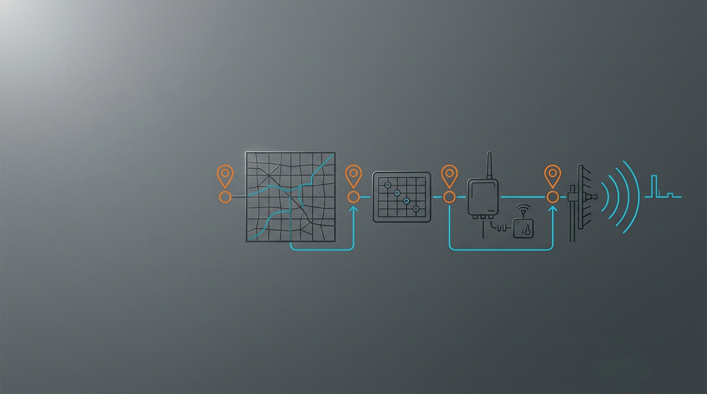
It helps to sketch the assembly as a chain rather than as “antenna plus cable.”

The same diagram prevents an accidental change of scope. Cable selection is not a substitute for confirming antenna pattern, radio bands or port count. It is one decision inside the installed RF system.
Choose cable data at the actual operating frequency and route length
Antenna cable loss changes with frequency, cable construction and length. That is why a generic attenuation chart or an unqualified “best coax” ranking is not enough for an IoT BOM. Read the data for the proposed cable part number at the frequency or frequencies your radio actually uses, and apply it to the measured installed route—not a convenient nominal run.
A manufacturer’s attenuation calculator or data sheet is useful only when it is used for a named cable, a stated frequency and an installed run length. Its result applies to that manufacturer’s published data, not to every cable that happens to share a marketing label. Treat it as a check on a documented candidate, not as proof that a different product has the same loss.
| Deployment condition | Compare first | Ask the supplier to provide | Do not infer |
|---|---|---|---|
| One narrow operating band | The exact cable data at the deployed band and the measured route length | Cable part number, attenuation data at the band, both terminations and proposed assembly length | A cable’s loss at a distant frequency. |
| Multi-band cellular router | Data across all active bands, plus every active RF branch | Band list, per-branch part number/length and documented interfaces | That one favorable band represents the complete radio range. |
| Antenna moved farther from the enclosure | Whether improved antenna placement offsets the added feed path in the system budget | Two route options with measured lengths and the data used for each | That a higher or clearer antenna location always wins. |
| Short equipment-room patch plus outdoor run | Each cable segment, transition and bulkhead | Segment list, connector/adapter stack and installation notes | That only the longest cable segment matters. |
For an end-to-end view, place the feeder as an installed loss term in the IoT link-budget workflow. That article explains how antenna gain, feed losses, path loss and receiver requirements interact. Here, the practical rule is narrower: do not claim a range improvement from cable family alone. The relevant comparison is the complete installed path, measured or modeled with the right radio and site assumptions.
A short route can still be the wrong assembly
Length is important, but it is not the only variable. A very short lead can be unsuitable if its connector is not the documented mate, its bend constraint is violated at the enclosure, or its termination is not intended for the expected handling. Conversely, a longer route may be justified when it reaches a much better antenna location—provided the trade-off is documented and validated in the system.
Keep the decision reviewable. Record the source of each attenuation value, the frequency it represents, the final route length and the configuration date. If a substitution is proposed later, repeat the review rather than carrying a number across cable families.
Specify the complete outdoor cable assembly
A cable spool is not an outdoor antenna assembly. The supplier, installer and reviewer should be able to identify every RF and mechanical transition from the device port to the antenna. This is where many apparently small unknowns accumulate: an extra adapter added to make a thread fit, a bulkhead added at a cabinet wall, or a weather-exposed joint that cannot be inspected after the mast is raised.
Use a completed-assembly record like this one:
| Assembly element | Record | Review question |
|---|---|---|
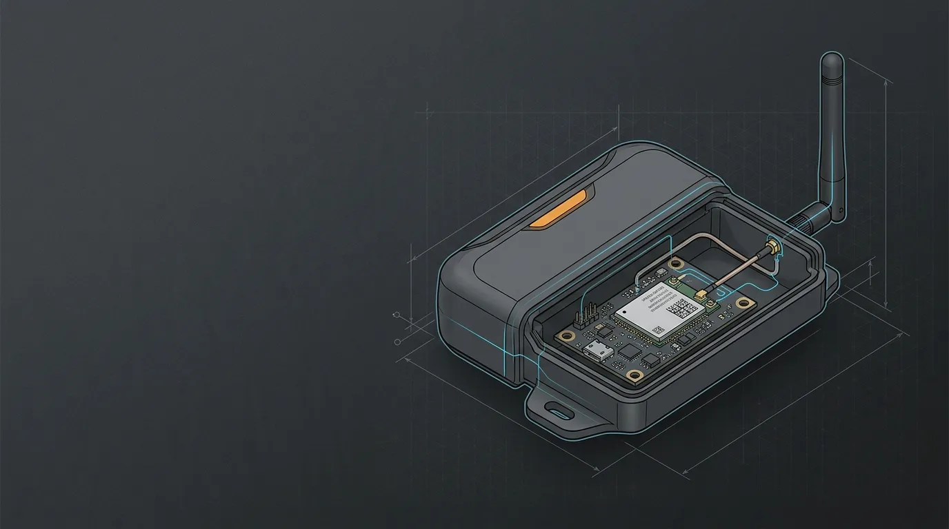
| Device port | Exact label, radio function, manufacturer interface designation and any approved external-antenna condition | Is this the intended cellular, LoRaWAN, Wi-Fi or other documented RF port? |
| Device-side cable end | Connector family and gender, cable part number, termination method and any adapter | Is the direct mate confirmed, rather than assumed from a photo? |
| Cable route | Final installed length, support points, bend locations and protected/unprotected sections | Does the BOM reflect the installed route, including service allowance? |
| Transitions | Each bulkhead, adapter, feed-through or other intermediate interface | Is every extra interface necessary, specified and accessible for inspection? |
| Antenna-side end | Connector family/gender, mating interface and mechanical support | Does it mate with the selected antenna without an undocumented conversion? |
| Installation record | Part numbers, revision/date, installer, photos and planned acceptance evidence | Can a replacement or fault investigation reproduce this path? |
When the mating faces are uncertain, stop before ordering adapters. The SMA versus RP-SMA identification guide shows why thread shape alone is not enough: the center contact convention matters as well. Use the exact device and antenna documentation wherever possible; a guide can help identify what needs verification, but it cannot certify an unknown port.
Connector care also belongs in the selection, not only in repair. Technical measurement guidance from Rohde & Schwarz explains that connectors, bends and handling can affect cable behavior, and shows measurement approaches such as calibrated cable-loss tests. Do not reproduce a measurement procedure without the appropriate equipment, calibration and competent operator. Instead, use the guidance to decide what evidence your project needs and who is responsible for obtaining it.
Match the jacket and mechanics to the installed route
For outdoor IoT antennas, the route often decides whether a cable specification is usable. A cable that performs acceptably on a bench may be exposed to UV, movement, water paths, abrasion, repeated cabinet access or a bend at the exact point where an enclosure door closes. “Outdoor rated” is not a complete installation plan.
Confirm the manufacturer’s instructions and the applicable installation requirements for the exact cable and accessories. Then review the route with the person who will install and maintain it.
| Route question | Evidence to request | Decision it supports |
|---|---|---|
| Is any section exposed? | Exact jacket/environment specification and the intended exposure condition | Whether that cable construction belongs on the exposed segment. |
| Where does the cable bend? | Data-sheet bend limitation and a route sketch or mock-up | Whether the planned path avoids a forced sharp bend. |
| Where is the weight supported? | Support/strain-relief plan and accessible fixing points | Whether connectors will be asked to carry cable load. |
| How does the route enter equipment? | Entry detail, service loop and inspection access | Whether the entry can be maintained without disturbing the RF path. |
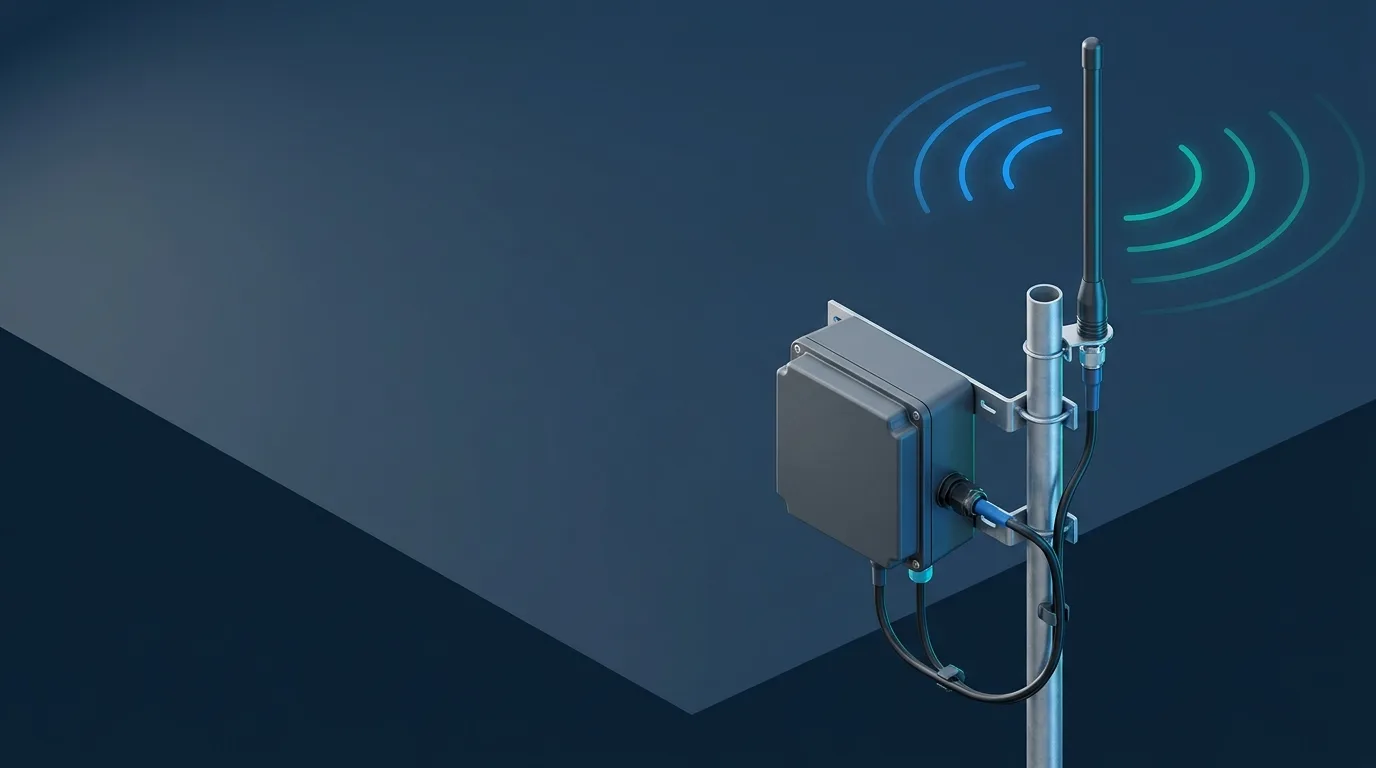
| Is the antenna on a mast? | Mounting and weather-entry plan for the complete installation | Whether the cable brief matches the site, not only the antenna catalog. |
For a gateway-and-mast installation, use the outdoor gateway feeder and weather-entry checklist alongside this cable brief. It is LoRaWAN-oriented, but its site-installation discipline is useful whenever a fixed gateway places an antenna outside. It does not turn a cable choice into a universal weatherproofing, grounding or lightning-protection claim; those items need their own product-, site- and code-specific design review.
Record every port in a MIMO or multi-radio installation
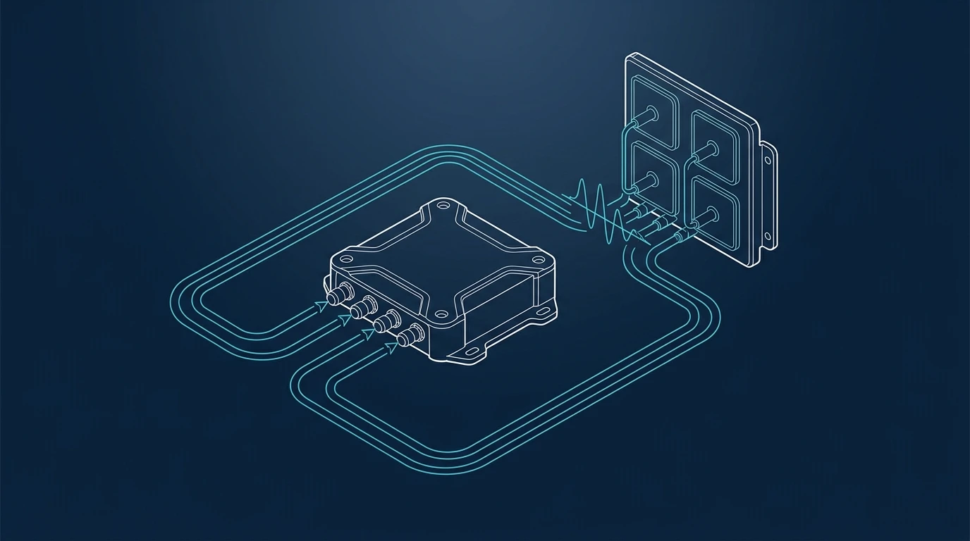
Do not let a single cable choice conceal several RF paths. Cellular routers, Wi-Fi equipment and combination gateways can expose ports that look similar while serving different radios or different MIMO/diversity branches. A cable assembly must be recorded per active port.
Create a simple branch table before the purchase order:
| Port / branch | Radio function and active bands | Cable part number and installed length | Interface stack | Inspection or test result |
|---|---|---|---|---|
| Branch 1 | Copy from the exact device documentation | Record after the route is measured | Device end → any transition → antenna end | Record method, date and result/status |
| Branch 2 | Copy independently; do not assume it matches Branch 1 | Record independently | Record independently | Record independently |
| Additional branches | Repeat for each documented active chain | Repeat | Repeat | Repeat |
The point is not to impose identical lengths or components on every radio by default. It is to avoid treating several paths as one when the device documentation assigns different functions, bands or interfaces. Use the router/MIMO guide to map each active MIMO feed path before deciding that apparently similar leads can be swapped. If the device is cellular-specific, its documented band and port map remains the authority.
Approve the installed feed path with evidence
An order can be technically complete and still fail at installation. Separate acceptance into three layers: document review, physical inspection and an RF or service test appropriate to the project. That distinction avoids two bad shortcuts—treating a clean photograph as proof of RF performance, or treating one connection event as proof that every cable branch is correct.
| Acceptance layer | Minimum evidence | What it can establish | What it cannot establish alone |
|---|---|---|---|
| Document review | Device port map, cable/connector part numbers, route length, manufacturer data and assembly revision | The proposed assembly is specified well enough to review | That the finished installation matches the proposal. |
| Physical inspection | Photos or inspection record of labels, interfaces, supports, bends, entry and accessible joints | The installed route appears to match the approved record | The actual RF response across the operating bands. |
| Validation | A documented test method suitable for the equipment and radio, plus a baseline where practical | Whether the completed system behaves acceptably under stated conditions | A universal range, throughput or reliability guarantee. |
The method may be a qualified cable measurement, a device-level comparison under controlled conditions, or a field check using the metrics and procedures documented for that radio. State the test conditions, equipment, operator and limits. If a result is inconclusive, investigate the port map, interface stack, actual route and antenna location before replacing a cable solely because it carries a “low loss” description.
For a broader stop/go workflow, the external-antenna compatibility record adds device support, bands, port count and installation conditions. Use it to keep the cable decision connected to the full external-antenna system without repeating every step in this article.
Turn the selection into an RFQ-ready cable brief
The fastest way to get a useful supplier response is to send a brief that distinguishes known facts from open questions. “Need a low-loss cable for an outdoor antenna” is a starting point; the record below lets an engineer review the actual assembly.
| RFQ field | Minimum useful entry |
|---|---|
| Device and deployment | Manufacturer/model/revision, country or region, and the radio function being served |
| Radio path | Port labels, documented operating bands, required chains and stated impedance/interface |
| Antenna target | Exact antenna or required frequency/pattern/mounting role; indoor/outdoor location |
| Cable route | Proposed cable part number, measured installed length, segment locations and service allowance |
| Interfaces | Both cable ends plus every adapter, bulkhead or transition, with mating status |
| Mechanical/environmental route | Exposure, bend locations, support/strain-relief plan, entry method and access constraints |
| Evidence requested | Relevant cable data at operating frequencies, assembly documentation, inspection plan and proposed validation method |
| Quantity and change control | Prototype/production quantity, permitted substitutions and revision-control requirement |
Use the IoT antenna compatibility checker to capture the cable-path requirements brief before an inquiry. It helps organize the inputs for review; it is not a terrestrial cable-loss calculator and it does not validate a device, cable or installation automatically. Attach port photos and documentation references when the interface or radio path remains uncertain.
FAQ: outdoor 50-ohm antenna coax cable
Can I use any outdoor coax cable that has the right connector?
No. A matching connector is only one part of the decision. Confirm the radio’s documented external port, the intended impedance, operating frequencies, actual installed route, cable data at those frequencies, every transition and the environmental/mechanical conditions. A 75-ohm TV/CATV cable should not be substituted into a 50-ohm IoT feed path merely because it is available or the ends appear adaptable.
How long can an outdoor antenna cable be before loss becomes a problem?
There is no universal maximum. The relevant loss depends on the exact cable, frequency, installed length and condition of the complete path, and its acceptability depends on the radio link and required margin. Measure the intended route, use the manufacturer’s data for the selected cable at the active bands, include the result in the system review, and validate the completed installation where it matters.
Do all MIMO antenna cables need to be the same length?
Not automatically. Start with the radio manufacturer’s port map and the antenna-system requirements. What matters first is that every required branch is correctly identified, documented and installed as intended. Record each branch’s cable part number, length and interface stack; do not assume visual similarity makes branches interchangeable or that matching lengths alone guarantees system performance.
Is a cable-loss calculation enough to approve the installation?
No. It is useful design evidence, but it does not prove connector mating, route condition, strain relief, antenna placement or the installed system’s behavior. Approve the documents, inspect the physical path and perform a test appropriate to the radio and available measurement capability.
Sources for technical verification
- Rohde & Schwarz: how to measure cable loss, for measurement concepts and the limits of an uncalibrated test.
- Tektronix: introduction to VNA basics, which includes examples of cable and adapter measurements; use the procedure and capability appropriate to the selected instrument.
- ITU-R: Recommendation P.525, a formal free-space reference when documented feeder loss is assessed in a wider radio-link model.
These references support a verification process, not a universal cable recommendation. Final selection should use the current data sheet for the exact cable and components, the documentation for the exact radio/antenna, and the conditions of the intended installation.