A Wi-Fi 6E external antenna is suitable only when its measured frequency response covers the channels your radio will use—including 6 GHz—after cable, connector and mounting losses are considered. A connector that fits, or a product label that says “tri-band,” does not prove that. Start with band edges, then check installed performance, MIMO port count, feed loss and mounting geometry. That order prevents the most common upgrade failure: replacing a working dual-band antenna with a nominally higher-gain part that performs worse on the actual device.
What makes an external antenna Wi-Fi 6E-ready?
Wi-Fi 6E is Wi-Fi 6 extended into the 6 GHz spectrum. A 6E radio is normally tri-band because 2.4 and 5 GHz remain useful for compatibility and coverage while 6 GHz adds cleaner spectrum and more room for wide channels. Intel’s 2.4, 5 and 6 GHz comparison describes that tri-band relationship and notes that 6 GHz operation still depends on country-specific approval.
| Band | What it is good at | RF trade-off | What the antenna must do |
|---|---|---|---|
| 2.4 GHz | Wider coverage, legacy devices and better obstacle penetration | Crowded spectrum; physically longer wavelength | Maintain matching and a useful pattern at the lowest band, where the mounting surface matters most |
| 5 GHz | A practical balance of capacity and coverage | More path loss than 2.4 GHz; some channels have regional restrictions | Cover the exact sub-bands enabled by the radio, not just a single center frequency |
| 6 GHz | Cleaner spectrum and more wide-channel choices | Highest path and obstacle loss; cable attenuation is more punishing | Show acceptable match, efficiency and pattern over the permitted 6 GHz channels |
At the same distance in free space, 6 GHz has about 8 dB more path loss than 2.4 GHz. Walls and enclosures can widen that gap. That does not make 6 GHz “short range” by definition, but it does make placement and delivered antenna performance less forgiving.
The permitted 6 GHz window also differs by market and device class. In the United States, FCC rules cover 5.925–7.125 GHz. Authorized operations include standard-power devices controlled by automated frequency coordination, low-power indoor devices, very-low-power devices and, under the 2026 FCC 26-1 order, geofenced variable-power devices—each with different conditions. The current Federal Register record for the 2026 order is the right starting point for US-specific boundaries. An antenna can cover a frequency; it cannot make a radio or installation legally authorized there.
Read the antenna data, not the Wi-Fi label
For an OEM or gateway project, ask for per-band evidence. Seven fields determine whether a Wi-Fi 6E antenna is a fit:
- Frequency range: the published lower and upper edges must include every channel the radio may select.
- VSWR or return loss: this shows how well the antenna is matched. Check band edges, not only a best-case center point.
- Efficiency: the share of accepted power that is radiated rather than lost as heat.
- Gain: efficiency plus pattern directivity, stated at a frequency and reference plane.
- Radiation pattern: “omnidirectional” usually describes azimuth; the vertical pattern can still have nulls.
- Polarization: it should suit the other end of the link and the device orientation.
- Impedance: 50 ohms is the system convention, not proof of a good match across three bands.
| Datasheet claim | Evidence needed before selection |
|---|---|
| “6 dBi” | Gain by frequency, pattern and whether cable loss is included |
| “6 GHz” | Actual lower/upper edges and VSWR or return-loss curve |
| “Omnidirectional” | Horizontal and vertical radiation patterns |
| “Tri-band” | Continuous or segmented coverage that matches the radio’s channel plan |
| “50 ohm” | Installed match with the real cable, connector and mounting surface |
Peak gain is especially easy to misread. A higher figure concentrates radiation in some directions; it does not create RF power. If a machine tilts, an access point sits above the client, or metal bends the pattern, a broad 2 dBi pattern can produce a more reliable link than a narrow 6 dBi maximum.
Cable loss can erase the 6 GHz gain
Gain is normally specified at the antenna terminal. The radio sees the complete assembly:
Delivered peak gain ≈ antenna-terminal gain − cable and connector insertion loss
If an antenna has a 6.0 dBi terminal peak and its finished cable assembly measures 4.5 dB insertion loss at the channel in use, the delivered peak is about 1.5 dBi before mounting effects. The 4.5 dB value is an illustration, not a universal RG174 figure. Cable construction, frequency, connector quality and production tolerances all matter, so request measured assembly loss at 2.4, 5 and 6 GHz.
This does not mean the shortest cable always wins. A two- or three-metre lead may move the antenna out of a steel cabinet, away from a noisy processor and above nearby obstructions. That placement gain can exceed the feed loss. Compare both configurations in the installed environment rather than optimizing the cable on paper.
For a fuller system calculation, use the framework in our IoT antenna link-budget guide. It keeps feed loss separate from antenna gain so the same dB is not counted twice.
MIMO means antennas, ports and geometry
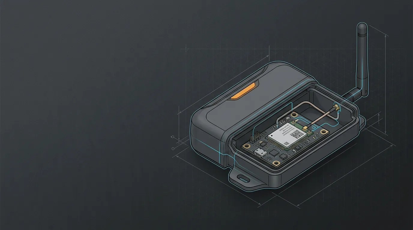
A 2x2 Wi-Fi radio has two RF paths. If the selected antenna has one connector, a 2x2 installation needs two antennas and two cable assemblies. One “high-gain” antenna on one port does not replace the second path.
Begin with these checks:
- Match the number of external antennas to the radio’s enabled chains.
- Confirm every connector’s series, gender and polarity; SMA and RP-SMA are not interchangeable.
- Use roughly half a wavelength at the lowest operating band as an initial spacing reference—about 6.25 cm at 2.4 GHz—then validate the real layout.
- Avoid routing both cables together beside the same noise source or conductive edge.
- Test orientation, isolation and throughput, not RSSI alone.
Spacing is only a starting point. Pattern correlation, enclosure geometry and the multipath environment determine whether the two paths provide useful diversity. For a production design, verify MIMO operation with the radio’s per-chain measurements and an installed over-the-air test.
The same one-complete-path-per-port rule applies in cellular systems; our external-antenna MIMO selection example shows why upgrading only one port leaves the second path as a system constraint.
Choose the mount for the enclosure and environment
| Installation | Useful starting form | Main risk to test |
|---|---|---|
| Desktop, router or access point | Direct whip or short remote base | Equipment shadowing and connector mismatch |
| Metal control cabinet | Remote magnetic or bracket mount outside the cabinet | Cable loss and pattern change on the mounting surface |
| Vehicle or machine | Magnetic mount on a repeatable metal location | Vibration, cable routing and changing orientation |
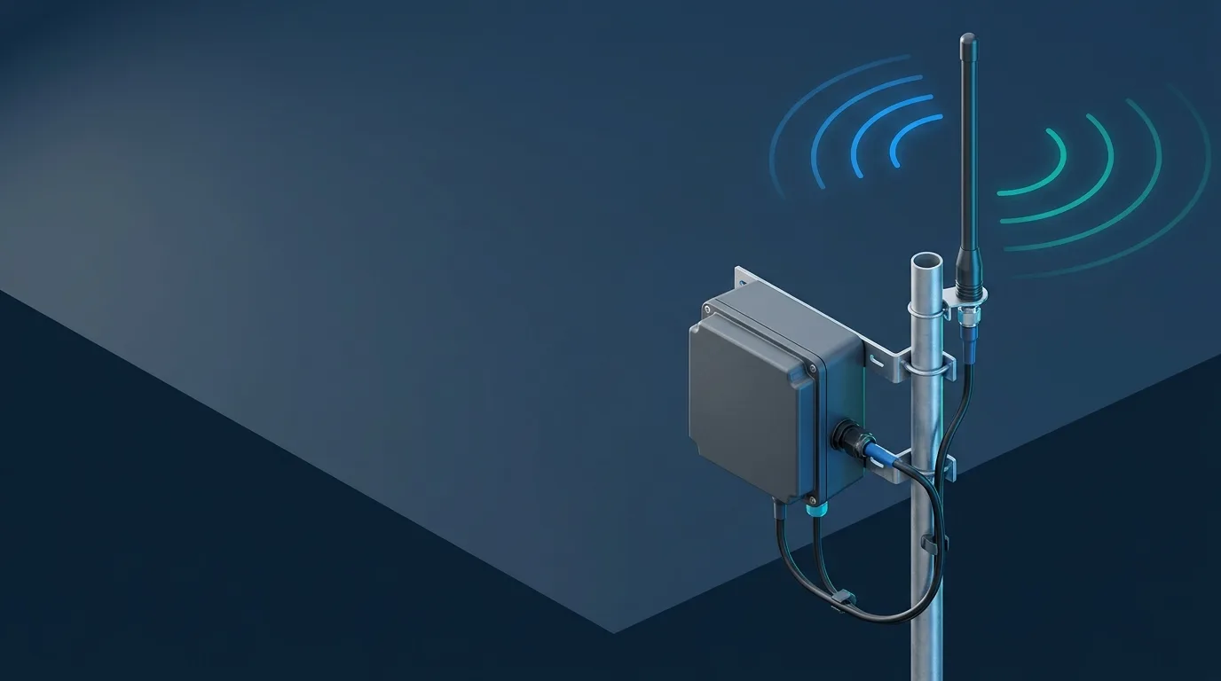
| Fixed outdoor access point | Weather-rated bracket, panel or outdoor omni | Water ingress, wind, grounding and regional device rules |
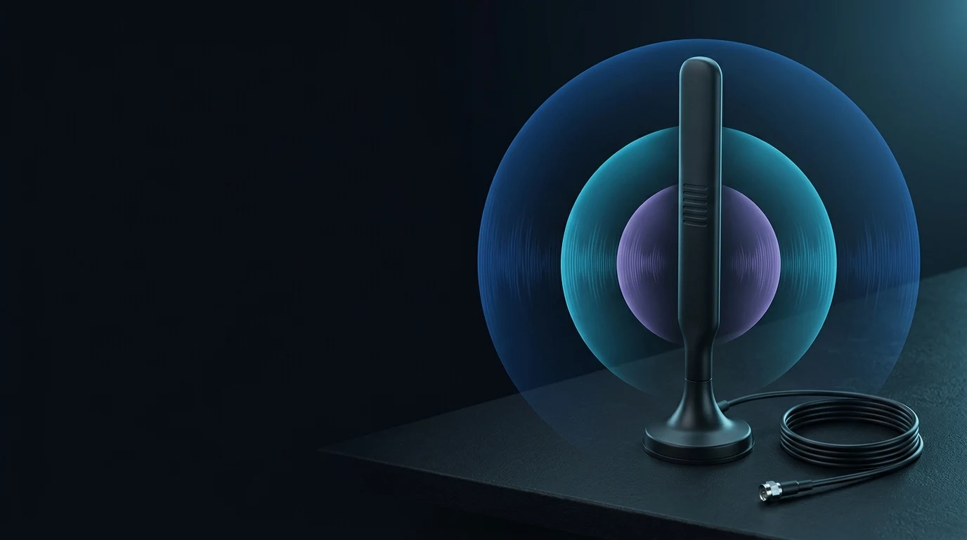
A magnetic base is valuable because it makes placement repeatable and removable. It does not automatically create an ideal ground plane across 2.4, 5 and 6 GHz. Roof curvature, cabinet seams and nearby conductors can alter both matching and pattern, so test the antenna on the actual surface. If the radio can sit at the enclosure edge with a short feed, compare direct-mount whip antenna options before accepting the loss of a remote cable.
The decision changes with the failure mode. If a plastic desktop terminal already has a short, well-tuned direct whip, adding three metres of coax may only spend margin. If the same terminal is moved inside a steel cabinet, the remote mount can recover far more signal than the cable consumes. On a vehicle, repeatability becomes the priority: choose a documented mounting zone, keep the cable route fixed and test the worst vehicle orientation. “External” is not automatically better; it gives the engineer control over placement, and that control has value only when the final location is validated.
If you are selecting across radio types and form factors, the IoT antenna buyer’s guide provides the broader band-first workflow, while the antenna selector helps narrow the starting category.
Where the LGW-2458-22ES fits—and where it does not
GNSource’s LGW-2458-22ES is a single-port magnetic-mount antenna intended for terminals, data-communication equipment and industrial IoT devices.
| Specification | LGW-2458-22ES |
|---|---|
| Frequency ranges | 2.4–2.5 GHz; 5.1–5.85 GHz; 5.9–6.4 GHz |
| Maximum gain | 6.0 dBi, excluding cable loss |
| VSWR | ≤2.0 |
| Pattern / polarization | Omnidirectional / linear |
| Impedance | 50 ohms |
| Cable / connector | 3 m RG174 / SMA-J, inner-thread and inner-pin |
| Dimensions | 158 × 36 mm |
| Operating temperature | -30 to +80 °C |
It fits a gateway or terminal that needs remote magnetic placement and whose enabled channels fall inside those three frequency windows. The important limitation is the upper band edge: 5.9–6.4 GHz does not cover the full 5.925–7.125 GHz US allocation. Treat it as a fit for the relevant lower 6 GHz channels, not as a universal full-band US Wi-Fi 6E antenna.
For 2x2 MIMO, specify two units and validate their installed separation and isolation. Before ordering, also confirm the mating connector and request assembly-loss data at the intended channels. Browse the magnetic-mount antenna range or send the radio, market and mounting details to GNSource Engineering.
Validate the installed assembly before production
Use a sample process that can be repeated on production units:
- Confirm the target countries, radio/module and enabled channel plan.
- Map every RF chain to its external port and verify connector polarity.
- Obtain or measure VSWR and cable-assembly insertion loss across all used bands.
- Install the antenna on the real enclosure, bracket or metal surface.
- Hold channel, power, distance and traffic constant; record per-chain RSSI/SNR, throughput and packet loss on each band.
- Repeat at worst-case orientation, obstruction and temperature, then check multiple production samples.
A benchtop antenna that passes at 6 GHz can detune when installed. Conversely, a longer remote cable can improve the complete link by fixing placement. Production approval should follow installed-system data, not an isolated antenna number.
Frequently asked questions
Does Wi-Fi 6E require a different antenna?
It requires an antenna characterized for the 6 GHz channels the radio uses. Some wideband 5 GHz antennas may work over part of 6 GHz, but connector fit or acceptable 5 GHz performance does not prove 6 GHz matching, efficiency or pattern.
Can a 5 GHz antenna work at 6 GHz?
Possibly over a limited range, but only measured data can confirm it. Check the antenna’s band edges, VSWR, efficiency and radiation pattern through the required 6 GHz channels. Do not infer coverage from the product name.
Does Wi-Fi 6E go through walls?
Yes, but 6 GHz normally loses more signal than 5 or 2.4 GHz over the same path. Wall material, thickness, angle and nearby metal dominate the result, so use a site test rather than a universal distance claim.
Is a higher-dBi Wi-Fi 6E antenna always better?
No. Higher gain reshapes the pattern and can create weak directions. Cable loss, mounting, polarization and MIMO geometry may matter more than the peak dBi number. Choose the lowest gain that closes the link with adequate margin and coverage.
For a Wi-Fi 6E antenna review, send GNSource the module, countries, channels, MIMO count, cable and connector, mounting surface and environment. That information is enough to reject an incompatible part before it reaches field testing.