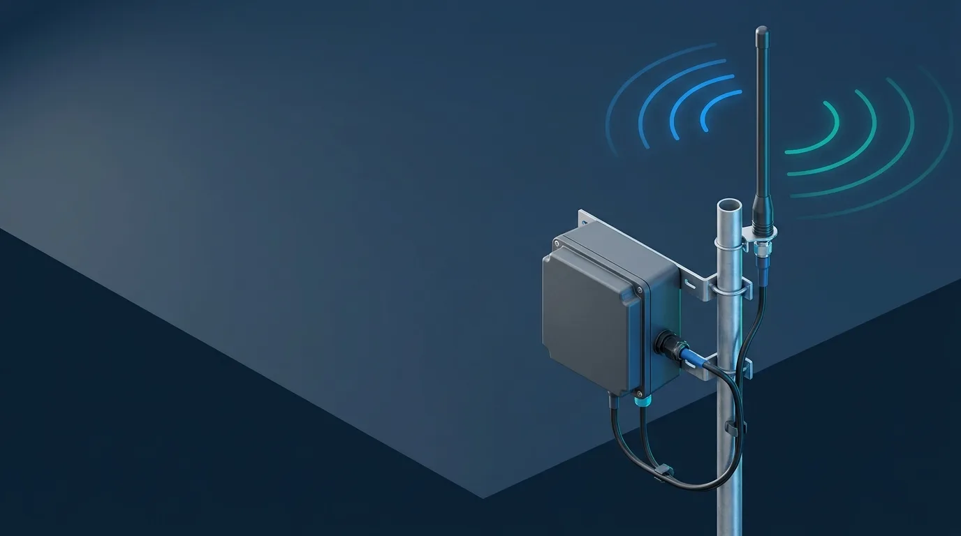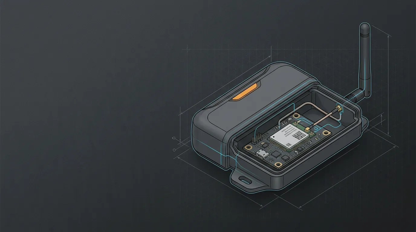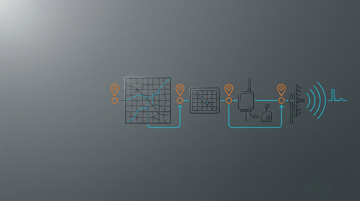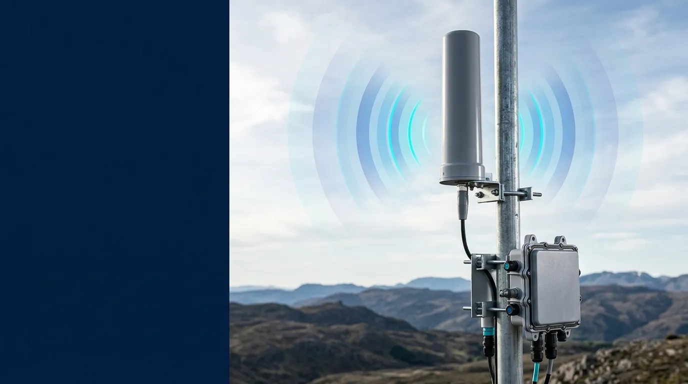
A fiberglass omnidirectional antenna is a strong fit for a fixed outdoor IoT gateway or base station when the site needs broad azimuth coverage and the antenna can be mounted above the main obstruction field. The selection is not just “pick the highest dBi.” Confirm the radio band, vertical beamwidth, gateway and node heights, cable loss, mast load, environmental evidence, connector path and grounding plan as one installed system. The radio-first IoT antenna selection framework is a useful starting point; this guide applies that logic to the outdoor fiberglass form factor.
Start with the fiberglass radome, not the marketing label
The fiberglass part is normally the radome: a protective enclosure around the radiator, often a collinear array for a vertical, fixed base-station antenna. The radome keeps the radiating elements away from rain, UV exposure, dust and handling while allowing radio-frequency energy to pass. It is not the source of the antenna’s gain by itself.
That distinction matters when comparing an outdoor fiberglass antenna with a whip, a panel or a bare element. Fiberglass construction can support a sealed, pole-mounted package, but the material does not prove a particular IP rating, wind-load test, temperature range or connector seal. Ask for those items at the model level. A marketplace listing that says “IP67” is evidence about that listing, not a universal property of fiberglass antennas.
Typical uses include a LoRaWAN gateway, a telemetry concentrator, a private-LTE or 4G router, a fixed 5G installation, and other point-to-multipoint IoT links. The common requirement is a stable outdoor location serving devices in multiple azimuths. If nearly all of the traffic is in one direction, a sector or panel antenna may use the available power more effectively.
Read “360° omnidirectional” as an azimuth specification
“Omnidirectional” describes the horizontal plane. A 360° horizontal beamwidth means the antenna is designed to radiate around the mast in azimuth; it does not mean equal signal at every height, distance or obstruction condition. Elevation is described by the vertical beamwidth, sometimes with an electrical downtilt value.
Gain changes that vertical shape. A higher-gain collinear antenna generally concentrates more energy near the horizon and narrows the vertical lobe. That can help an elevated gateway serving nodes across a relatively flat area. It can hurt when the gateway must reach devices far below the mast, on hillsides, or close to the tower base. A low-gain, wider-beam model can be the better engineering choice even when its headline dBi number looks less impressive.
Keep four variables together:
- Height: the gateway and node elevations set the angles the vertical pattern must cover.
- Polarization: most examples in this product family are vertically polarized, so the remote radiator should be installed with the same orientation.
- Obstructions: roofs, tanks, trees, terrain and the mast itself can block or scatter energy; “omni” does not remove those losses.
- Traffic geometry: a one-sided or corridor-like site may justify a directional or sector antenna instead.
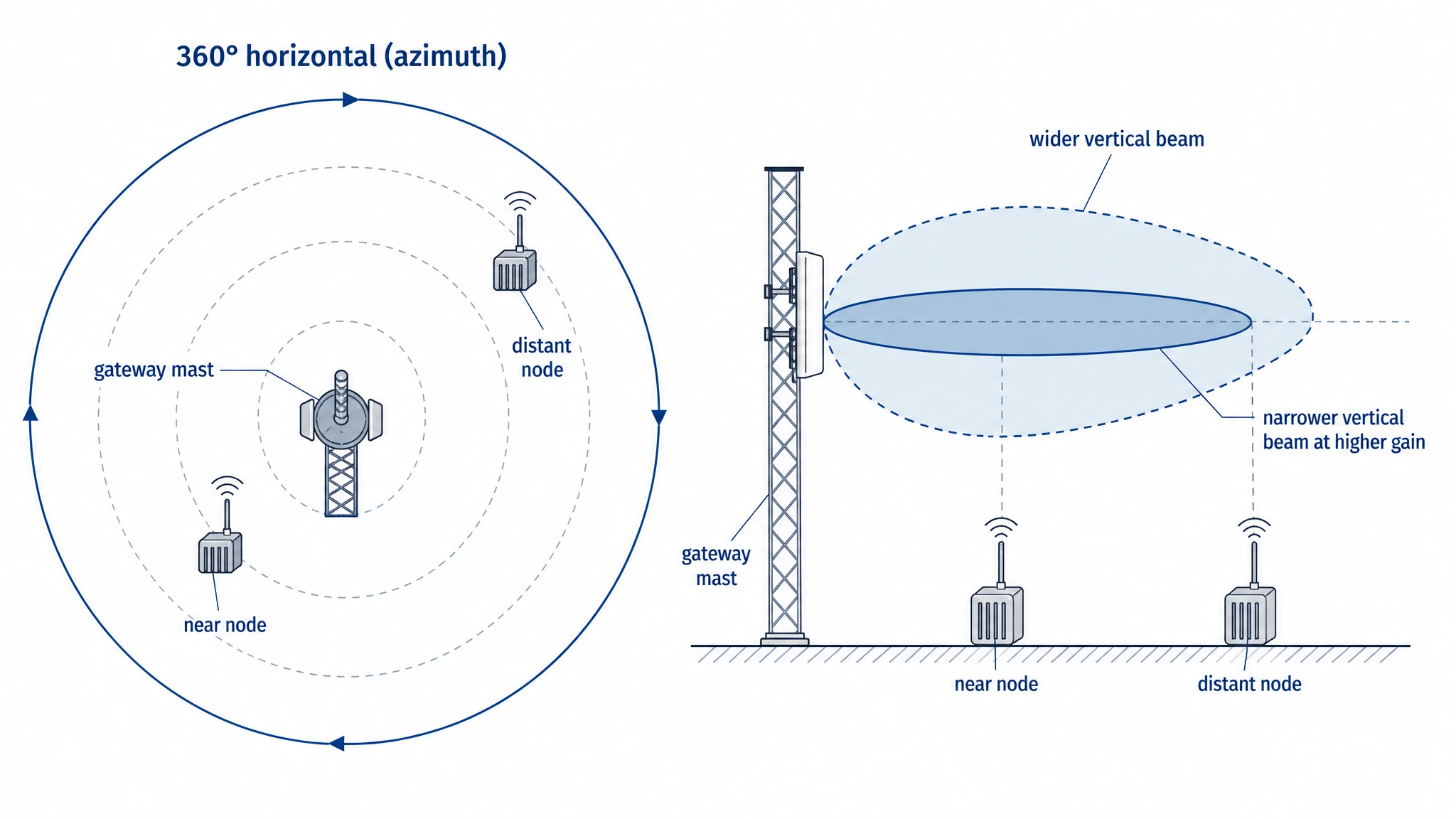 A fiberglass omnidirectional antenna can cover the full azimuth while its vertical beam still concentrates energy around a particular elevation.
Choose gain and beamwidth from site geometry
Use the site geometry before comparing model numbers. The table is a screening tool, not a substitute for a link budget or a measured field test.
| Site condition | What to favor | What to verify |
|---|---|---|
| Low gateway with nodes above and below it | Wider vertical beam; moderate gain | Near-field clearance and the steepest node angle |
| Elevated mast over a broad, fairly level area | More gain with a narrower vertical lobe | Horizon coverage, mast height and Fresnel clearance |
| Point-to-multipoint nodes near the horizon | Higher realized gain can help | Cable loss, downtilt and whether nearby nodes fall outside the lobe |
| Hillside, valley or mixed elevations | Wider beam or a second site | Elevation angles, terrain and seasonal foliage |
| One-sided or obstructed traffic | Sector/directional alternative | Whether an omni wastes power behind the site |
Do not treat dBi as a range promise. dBi and dBd are different gain reference units, so compare like with like unless the supplier provides a documented conversion. The link sees realized gain in the direction of the remote node, minus connector and coax losses. A 10 dBi antenna with a 35° vertical beam can be a worse choice than a 3 dBi, 35° or wider model if the nodes sit outside the main lobe or the longer feed line consumes the difference. For the arithmetic, use the installed IoT antenna link-budget guide, and calculate both directions when the gateway and device have different transmit powers or sensitivities.
Match the frequency before comparing model numbers
The frequency range is the first hard gate. A model that is mechanically convenient but outside the radio’s enabled channels is not a usable base-station antenna. The following examples are taken from GNSource’s fiberglass-omni product records; confirm the current datasheet, regional channel plan and connector option before ordering.
| Example model | Frequency | Gain / pattern | Vertical detail | Connector / note |
|---|---|---|---|---|
| LGW-301-340-BLG01 | 301–340 MHz | 3 dBi, 360° H | 10° V | N Male, DC grounded |
| LGW-MO470N1 | 470–510 MHz | 5 dBi, 360° H | 45° V, 5° electrical downtilt | N-Male, 20 W |
| LGW-703-2690-BLG02 | 703–960 / 1710–2690 MHz | 3 dBi, 360° H | 35° V | N Male, wideband cellular |
| LGW-3.3G-BLG02 | 3300–3400 MHz | 5 dBi, 360° H | 30° V | N Male, DC grounded |
| LGW-4.9G-BLG02 | 4800–5000 MHz | 7 dBi, 360° H | 30° V | N Male, DC grounded |
Band-specific constraints still matter. For sub-GHz LoRa or telemetry work, compare the regional plan and mounting clearance with the 433 MHz antenna placement guide. For a cellular gateway, the 4G LTE external antenna guide covers band and placement decisions that a product table cannot. A private-network or fixed-wireless design may also need the broader 5G IoT antenna form-factor guide.
Qualify wind, weather and the mounting path
Treat a catalog value as evidence to review, not a universal site rating. The GNSource fiberglass product records list a 60 m/s wind datum for several models. Scope that number to the relevant product line and model, then check the mast, pole clamp, bracket, fasteners, antenna projected area, height and local structural requirements. A 60 m/s antenna value does not automatically qualify a tall mast on a coastal roof.
Before releasing the mechanical design, record:
- fiberglass, UV and corrosion evidence for the selected model;
- operating temperature range and any storage or cycling limits;
- a model-specific IP or ingress test claim, if one is required;
- wind-load value and the test or calculation basis;
- pole diameter, U-bolt or bracket compatibility, fastener material and torque;
- cable drip loop, bend radius, strain relief and the point where water leaves the assembly;
- salt, dust, ice, wash-down and inspection conditions at the site.
The cable entry often fails before the radome. Keep the connector facing down or protected as the design permits, use the specified gasket or weatherproofing method, and leave a service loop that does not pull on the connector. A good-looking fiberglass tube cannot compensate for a pinched coax or a loose pole clamp.
Treat the N connector and coax as part of the antenna
N-type is common on outdoor base-station antennas because it is a robust 50-ohm interface with threaded mating. It is not a guarantee that the installed joint is weatherproof. Confirm N Male versus N Female, mating torque, cable diameter, bend radius, sealing boot or tape, and whether the chosen cable assembly has loss data at the actual operating frequencies.
Amphenol RF describes N-type products as rugged, weatherproof RF interconnects and notes that weather-resistant or IP-rated sealing options are design-specific. Read its N-Type connector guidance as connector context, then follow the antenna and cable manufacturer’s assembly instructions.
Long coax consumes the gain you thought you bought. Put the cable, connectors and any surge protector into the link budget; measure the finished assembly when the frequency is high, the cable is long or the margin is small. If the radio is inside a cabinet, a shorter low-loss route can outperform a higher-gain antenna at the end of an unnecessarily long feed.
Separate DC grounding from complete lightning protection
“DC grounded” is an antenna or RF-path property. It can provide a DC path through the radiator or feed interface, but it does not by itself design the mast bond, coaxial surge protector, grounding electrode, building bond, down conductor or site lightning-protection system.
That distinction is important for an outdoor IoT base station. The installation may need a bonded mast, a correctly located coaxial arrestor, a low-impedance route to the site grounding system, and inspection by a qualified installer under local rules. The NFPA 780 publication defines a standard for the installation of lightning-protection systems; it is a scope reference, not a substitute for the design applicable to your building and jurisdiction.
Do not advertise a DC-grounded antenna as “lightning safe.” Ask what is grounded, where the bond is made, how the coax enters the building, and how the complete system is inspected. If a model is not specified as DC grounded, do not infer the feature from its fiberglass radome or N connector.
Run this installation and acceptance checklist
- Confirm the radio: record the enabled channels, polarization, impedance, connector gender, conducted power and sensitivity.
- Map the geometry: document gateway height, node elevation range, azimuth distribution, obstructions and the reason an omni is appropriate.
- Select the model: capture frequency range, gain, vertical beamwidth, downtilt, temperature, wind and mounting data from the current sheet.
- Qualify the structure: check pole/bracket diameter, projected area, fasteners, corrosion protection and the site’s structural calculation.
- Build the feed path: specify cable type and length, connector assembly, bend radius, drip loop, strain relief and ingress seal.
- Complete the grounding design: define DC bond, mast bond, arrestor, building entry and local inspection responsibilities separately.
- Measure the installed result: use VSWR/return loss where available, then test RSSI/RSRP, SNR, throughput or packet delivery at the worst expected node heights and orientations.
- Record the as-built state: keep model and serial information, photographs, torque/seal checks, test results, weather conditions and the maintenance interval.
Choose a model and request the right evidence
Once the band, geometry and installation constraints are known, compare the GNSource fiberglass omnidirectional antenna range by frequency and pattern—not by gain alone. For an RFQ, provide the radio/module, channels, gateway and node heights, target coverage, cable type and length, connector, pole or bracket, wind exposure, temperature, salt or dust conditions, and grounding constraints. That information lets a supplier check model fit before a prototype becomes a field problem.
Frequently asked questions
Does 360° mean equal coverage at every height?
No. It describes the horizontal azimuth pattern. Vertical beamwidth, mounting height, downtilt, terrain and obstructions determine how much energy reaches devices above or below the main lobe.
Is higher gain always better on a fiberglass base-station antenna?
No. Higher gain often narrows the vertical pattern. It can help a level, elevated point-to-multipoint site and hurt a hillside, valley or close-in node distribution. Compare the complete installed pattern and feed loss.
What does a fiberglass radome do?
It protects the internal radiator from weather, UV exposure, dust and handling while allowing RF energy to pass. The radome material alone does not establish a universal IP rating or wind qualification.
Is an N connector automatically waterproof?
No. The connector family, sealing option, mating torque, cable assembly and weatherproofing method all matter. Follow the exact product instructions and inspect the cable entry after installation.
Does DC grounded mean the antenna is lightning safe?
No. DC grounding is only one property of the antenna or feed path. The mast, bond, arrestor, grounding electrode, building entry and local lightning-protection design still need to be addressed.
When should I choose a different form factor?
Choose a sector or directional antenna when traffic is concentrated in one direction and a whip or another compact form when the installation is close to the radio or mobile. A fiberglass omni is most useful when a fixed outdoor site needs broad azimuth coverage and the vertical geometry is understood.