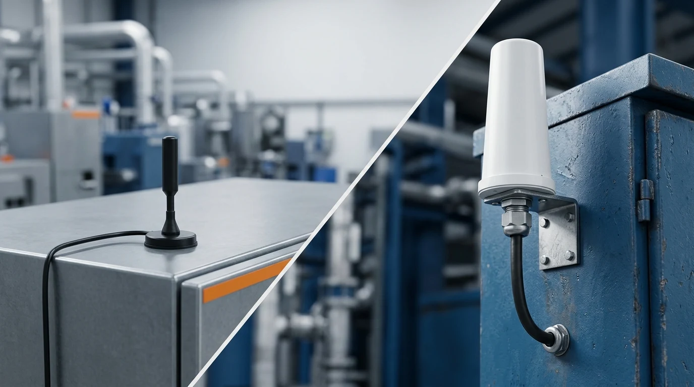
A magnetic mount is usually the right starting point when you need a fast, reversible IoT deployment on a suitable metal surface. A permanent mount earns its extra installation work when the asset is long-lived, exposed, tamper-prone, non-ferrous, or dependent on a repeatable sealed cable entry. The mount does not decide RF performance by itself: antenna design, operating band, mounting surface, placement, cable and connector still have to be qualified together.
This guide compares the two installation strategies for gateways, routers, fleet assets and field equipment. It is written for engineering and procurement decisions—not as a universal range claim for one radio type.
Magnetic mount vs permanent mount at a glance
| Decision factor | Magnetic mount | Permanent mount | Best fit |
|---|---|---|---|
| Installation | Tool-light; repositionable and removable | Drilling, bracket, mast or through-panel work | Prototype or production asset, respectively |
| Substrate | Needs a suitable ferrous, reasonably flat surface | Works with a bracket, through-panel or mast designed for the substrate | Metal cabinet/roof vs non-ferrous enclosure |
| Cable entry | Coax often routes through a door or existing opening; protect it from pinching | Defined gland, bulkhead or sealed entry can be designed in | Temporary route vs controlled production route |
| Service and security | Fast to inspect or move, but easier to remove or steal | Harder to move and usually more repeatable | Field trials vs long-lived or tamper-prone assets |
| Qualification focus | Surface, coupling, vibration, wind, dirt and cable strain | Structural load, sealing, corrosion, grounding and service access | The actual environment, not the label |
The comparison is not “easy antenna versus better antenna.” It is a choice about how the complete antenna assembly attaches to the asset and how that attachment will be maintained. If you change the mount and the radiator at the same time, you cannot tell which change caused a different RSSI, VSWR or throughput result.
When a magnetic mount is the better engineering choice
A magnetic antenna mount is valuable when the deployment needs to move faster than a mechanical redesign. Common examples include:
- a proof-of-concept gateway that will be tested at several sites;
- a fleet retrofit where drilling each vehicle would create downtime or affect a lease;
- a temporary cellular router or Wi-Fi terminal on a steel cabinet;
- a service asset that must be removed before transport, inspection or repair.
The practical benefit is control of placement without permanently changing the enclosure. You can move the antenna away from a processor, cabinet edge or cable bundle, then repeat the test at a documented location. GNSource’s magnetic-mount antenna options for IoT deployments cover 433 MHz ISM, cellular and Wi-Fi form factors so the band and connector can be selected independently from the installation decision.
That convenience has conditions. The base needs a suitable ferrous surface; paint, dirt, curvature, seams and nearby conductors can change the mechanical hold and RF coupling. A conventional magnetic base will not attach magnetically to bare aluminum or fiberglass. If the equipment has a non-ferrous wall, use a mechanically secured bracket or a ferrous backing plate that is designed for the load, then verify the antenna’s RF counterpoise assumptions. If no suitable mounting solution can be documented, a bracket, through-panel or mast installation is the more honest starting point.
When permanent mounting earns its extra installation work
Permanent installation is justified when the asset lifecycle makes repeatability and protection worth the labor. Think about a fixed outdoor gateway, a vehicle that will carry the same radio for years, a cabinet that must pass a defined ingress test, or a site where an exposed removable antenna is a tamper or theft risk.
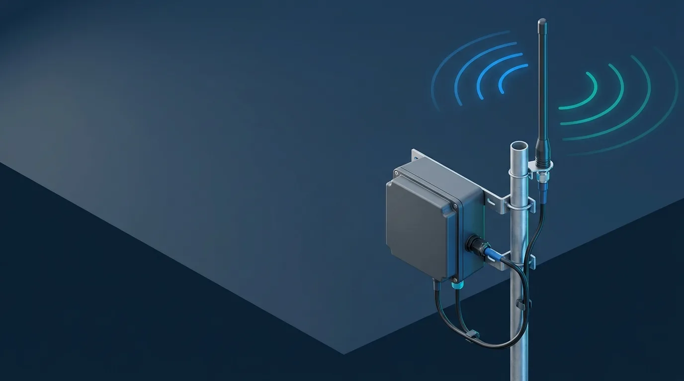
“Permanent mount” is not one design. It may mean an NMO or through-hole mount, a lip or bracket mount, a mast clamp, or a sealed bulkhead with the antenna mounted outside the enclosure. Each method has different structural, RF and sealing assumptions. A through-panel mount can create a clean coax path but needs a verified hole, washer, gasket and torque procedure. A mast mount may provide height and coverage but adds wind load, bracket strength and grounding work. A vehicle bracket can avoid drilling while still being more repeatable than a loose magnetic base.
The trade is front-loaded effort for a known production configuration. You can define the antenna location, bend radius, strain relief, drip loop, connector access and service interval once, then repeat it across units. That is difficult to achieve when every installer chooses a slightly different magnetic position.
The RF decision: ground plane, placement and cable
The phrase “ground plane” hides three different ideas. An RF counterpoise is part of the antenna’s electromagnetic environment. A DC bond is an electrical connection. A safety or lightning-grounding scheme is an installation responsibility. A magnetic base can couple RF energy to a conductive surface without creating a DC bond, and neither fact settles the safety requirements for an outdoor site. For installation context only, Firestik’s magnetic-mount note and Signal Stuff’s mag-mount versus NMO guidance make the same temporary-versus-permanent distinction; neither is a substitute for the exact antenna datasheet or an installed test.
Treat the mounting surface as part of the antenna system. A steel vehicle roof, cabinet wall or plate may support the antenna’s intended pattern; a narrow edge, curved panel, seam, battery, solar frame or fiberglass wall can change it. The 433 MHz mounting and ground-plane guidance explains why a magnetic whip still needs clearance and a suitable RF environment. The same principle applies to cellular and Wi-Fi, but the frequency, radiator and matching network change the result.
Cable routing is the other half of the installation. A long RG174 or RG58A/U lead can consume margin, while a pinched cable through a vehicle door can create an intermittent fault. A remote magnetic location can nevertheless improve the complete link if it moves the antenna outside a steel enclosure or away from a noisy processor. Compare the installed assembly, not the antenna’s headline gain. Use the external 4G antenna placement guidance, the 5G antenna form-factor selection guide, and the IoT link-budget checks for the installed antenna when the feed length or mounting position changes.
For a fair test, keep the radio, frequency, radiator, cable family, connector, transmit settings and measurement location constant. Change only the mounting method or surface condition. Record VSWR or return loss where the radio exposes it; otherwise record per-chain RSSI/SNR, throughput, packet loss and reconnect behavior. A universal “permanent mount adds X dB” statement is not defensible without that controlled comparison.
Mechanical and environmental checks before installation
| Check | Magnetic mount question | Permanent mount question |
|---|---|---|
| Movement | Is the surface and product rating appropriate for vibration and wind? | Does the bracket, stud or mast carry the load with margin? |
| Water | Can rain run into the connector or cable path? | Is the gland, gasket or bulkhead sealed and serviceable? |
| Finish | Can dirt under the base abrade paint during vibration? | Will drilling, clamp pressure or corrosion protection affect the substrate? |
| Security | Can the antenna be removed without tools or noticed? | Can fasteners, cable and service loops be protected from tampering? |
| Maintenance | Can a technician inspect and reposition it quickly? | Can the assembly be replaced without opening a sealed enclosure? |
Use the exact product documentation for the mechanical limit. For example, GNSource’s 433 MHz antenna guide lists a 120 km/h wind rating for the LGW-XP 433 MHz magnetic-mount model and identifies a magnetic base / clamp bracket mounting arrangement. That number is not a blanket rating for every magnetic antenna, vehicle speed, bracket or surface. LGW-5G-JBXP01 and LGW-2458-22ES have different bands, dimensions, cables and temperature ranges; their mechanical qualification must be checked from their own specifications.
For a magnetic installation, clean the surface, document the location, protect the coax from pinch and abrasion, and inspect the base after vibration or weather exposure. For a permanent installation, define the hole or bracket geometry, gasket or gland, fastener torque, cable bend radius, strain relief, drip path and corrosion-control method before the first production unit.
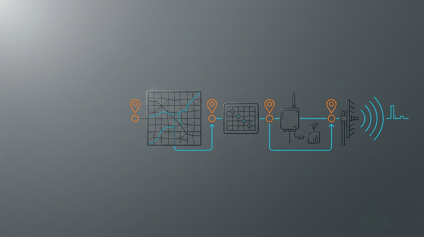
A practical selection workflow for IoT deployments
- Start with the radio and market. Confirm the operating bands, enabled channels, MIMO chain count, connector gender and any radio-specific authorization requirements. The FCC OET Knowledge Database is a starting point for US equipment-authorization guidance; it is not a mounting standard.
- Identify the substrate. Record whether the antenna will sit on steel, aluminum, fiberglass, plastic, a vehicle roof, a cabinet wall or a mast. Note curvature, seams, paint, nearby metal and available clearance.
- Classify the asset lifecycle. Mark the deployment as prototype, temporary site, leased vehicle, serviceable fleet asset, fixed outdoor gateway or permanent infrastructure.
- Map mechanical and security loads. Include vibration, wind, wash cycles, salt or dust, temperature, theft risk, maintenance access and the consequence of a loose cable.
- Choose the mount family. Select magnetic, bracket, through-panel, NMO, mast or another method that satisfies the substrate and lifecycle constraints. Do not choose from RF gain alone.
- Confirm the complete feed. Match cable type and length, connector series and polarity, bend radius, strain relief and enclosure entry. Request assembly-loss data at the frequencies that matter.
- Validate installed behavior. Test the final surface and position at the worst expected orientation and environment. Approve the configuration only after RF and mechanical results are repeatable.
Installation acceptance checklist
Before releasing an IoT antenna installation to production, record:
- substrate material, dimensions, finish and the exact mounting location;
- antenna model, frequency coverage, polarization, impedance and connector;
- cable type, length, bend radius, service loop and strain relief;
- magnetic-base cleanliness and movement inspection, or permanent fastener/gland torque and seal inspection;
- clearance from processors, batteries, solar frames, other radios and conductive edges;
- VSWR/return-loss data or a repeatable device-level RF test;
- throughput, packet-loss, reconnect and per-chain measurements where relevant;
- worst-case orientation, temperature, vibration, wash or wind exposure;
- tamper, theft, corrosion and maintenance checks;
- the as-built photographs and the configuration record that future technicians can reproduce.
The IoT antenna selection framework is useful for the band-first step. Once the installation is changed, rerun the link-budget and field-test assumptions rather than carrying an old range estimate forward.
Frequently asked questions
Is a magnetic mount antenna as good as a permanent mount?
It can be, but there is no universal answer. If both use the same antenna design on a comparable conductive surface, a clean magnetic installation can perform well. A permanent mount may be more repeatable or better protected, but drilling alone does not create RF gain. Compare the installed antenna, surface, cable and placement.
Does a magnetic antenna need a ground plane?
Some antenna designs use a conductive counterpoise; others are designed to operate with little or no ground plane. A magnetic base does not automatically tell you which design you have. Follow the product’s mounting assumptions and validate the match and pattern on the actual surface. Keep RF counterpoise separate from DC and safety grounding.
Can a magnetic mount be used on aluminum or fiberglass?
A conventional magnetic base will not hold to bare aluminum or fiberglass by magnetism. Use a mechanically secured bracket or a ferrous backing plate that is sized for the load, then verify whether the antenna’s RF design expects a conductive counterpoise. If the environment is windy or vibrating, use the exact product and mounting documentation rather than assuming a plate or permanent installation is equivalent.
Is a permanent antenna installation always more reliable?
Not automatically. A poorly sealed hole, stressed coax or weak bracket can fail earlier than a well-maintained magnetic installation. Permanent mounting improves repeatability and protection only when the structure, ingress path, cable relief and service process are designed and inspected.
How should I compare magnetic and permanent mounts for a vehicle or IoT gateway?
Hold the radio, antenna, cable and test conditions constant. Compare the same band and channel plan on the real roof, cabinet or bracket. Record RF diagnostics and mechanical observations, then choose the method that meets the link margin, environmental and maintenance requirements with the least lifecycle risk.
If you are selecting a magnetic antenna for a gateway, router, vehicle or field asset, browse the GNSource magnetic-mount antenna range or contact GNSource Engineering with the radio band, substrate, cable length, connector, environment and deployment lifecycle. Those details are enough to check fit before a prototype becomes a production problem.