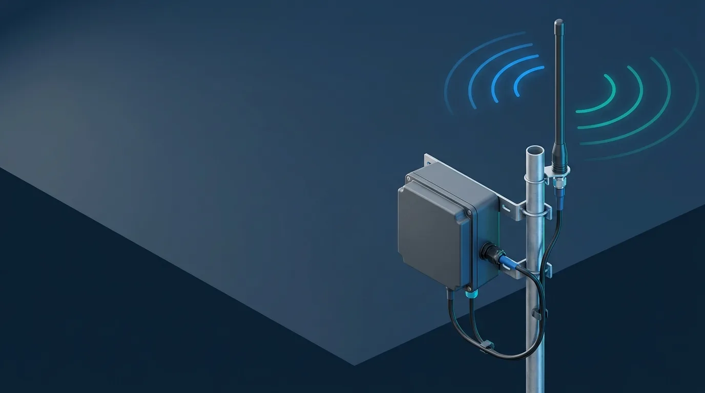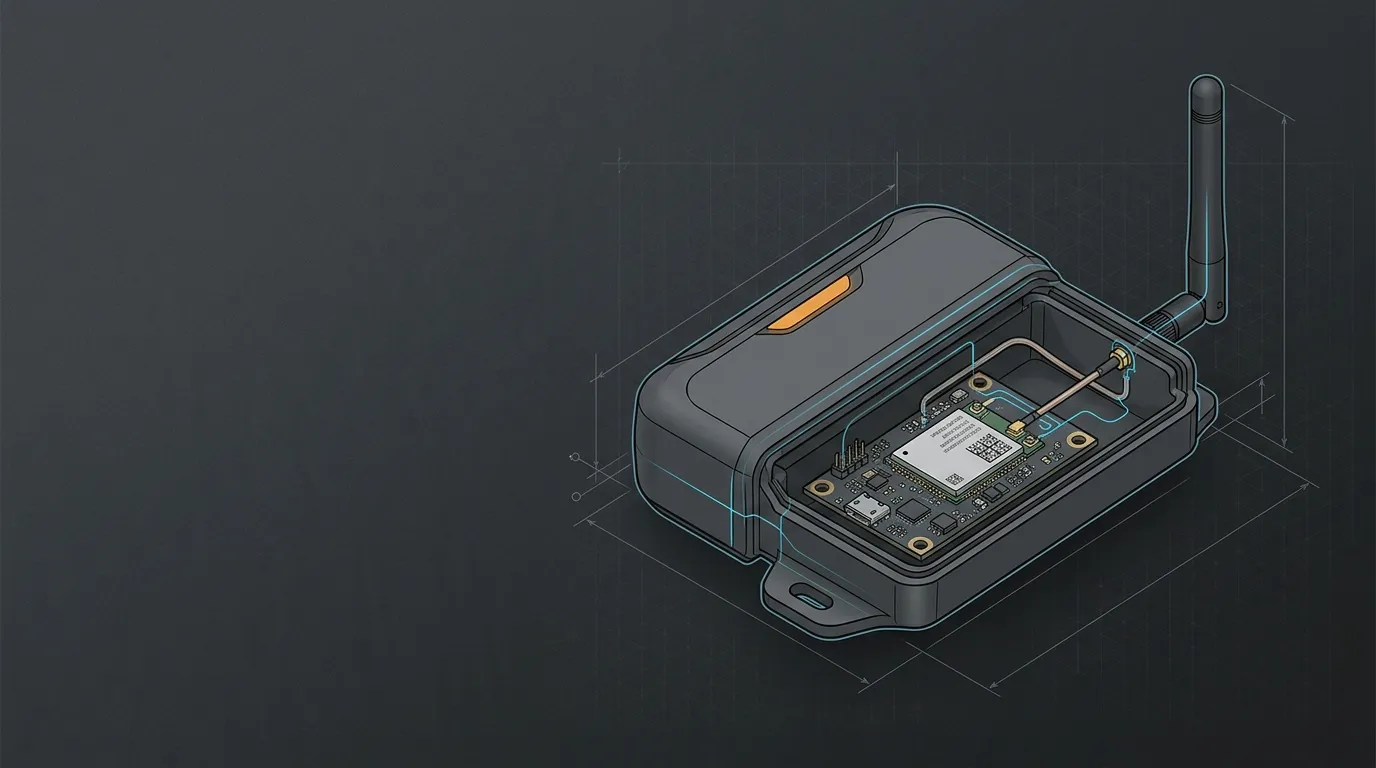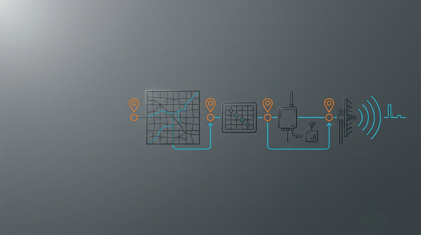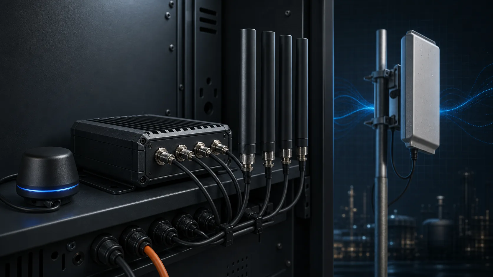
A 4G 5G router external antenna is a good upgrade only when four things agree: the router has external cellular RF ports, the antenna covers the carrier bands in use, the number of leads matches the router’s MIMO chains, and the connector/cable/installation path preserves the benefit. That is why the right starting point is the router manual and a port map—not the largest dBi figure in a product listing. For the broader radio-first method, start with the IoT antenna buyer’s guide.
Diagnose the WAN problem before buying an antenna
First, establish whether the weak link is cellular WAN reception or the local Wi-Fi network. An external cellular antenna can improve the radio path between a router and a mobile network. It does not extend Wi-Fi coverage through a warehouse, repair a poor mesh layout, or remove congestion at a serving cell.
Use the router’s status page and test close to the router. If the cellular indicators—such as RSRP, RSRQ, SINR, connected LTE/5G band or carrier aggregation—are poor, a better external cellular installation may be worth evaluating. If those indicators are healthy but users lose service at the far end of the building, investigate access-point placement and Wi-Fi design instead; the Wi-Fi 6E external antenna guide covers that separate RF chain.
An antenna is also the wrong purchase when the router has no external cellular ports, the carrier is rate-limiting the service, or the router is already in a clear location with a healthy cellular signal. Moving the router toward a window or higher position is a useful zero-cost baseline. GL.iNet makes the same point in its external cellular antenna guidance: stronger signal does not automatically become faster internet.
Confirm cellular bands and ports first
Create a one-page device record before comparing antenna families. It should come from the exact router model’s manual or product sheet—not a photo of a similar device. Cellular, Wi-Fi and GNSS connectors may appear on the same enclosure yet serve different radios.
| Check | What to record | Why it changes the antenna choice |
|---|---|---|
| Cellular modem and region | Router model, carrier, deployment country and enabled LTE/5G bands | A mechanically compatible antenna can still miss the coverage or capacity bands that matter at the site. |
| External RF ports | Count and labels: MAIN, AUX, DIV, PRI, MIMO1/MIMO2 or equivalent | Lead count must follow the radio’s cellular chains. |
| Connector interface | Family and mating gender from the manual | SMA, RP-SMA, TS9 and U.FL are not interchangeable labels. |
| Port function | Cellular versus Wi-Fi versus GNSS | A Wi-Fi antenna belongs on a Wi-Fi port, not a cellular port. |
| Installation envelope | Fixed, vehicle, cabinet, indoor or outdoor; cable route and ingress point | Pattern, mount, cable assembly and sealing depend on the real environment. |
Industrial routers illustrate why the labels matter. Cisco documents models with distinct main/diversity cellular ports and others with four cellular connectors for primary and secondary MIMO paths; its IR1800 antenna-selection guide also shows that port names are device-specific. Treat any table in this article as a workflow, not a substitute for that manual.
For every candidate antenna, compare the specified frequency range with the carrier bands and network mode actually used. “5G antenna” is not enough: many industrial deployments need low cellular bands for coverage, while others need sub-6 GHz mid-band support. In the United States, T-Mobile, Verizon and AT&T deployments can differ by site, plan and device, so record the router’s actual connected bands rather than selecting from carrier branding alone. The existing 4G LTE external antenna guide is useful for the LTE band-and-placement layer; the 5G IoT and fixed-wireless guide adds the FR1 and fixed-installation context.
Match MIMO chains to antenna leads
MIMO uses multiple radio paths to improve reliability and, where the network and device support it, throughput. In practical antenna selection, it creates a simple purchasing rule: provision the external leads and antenna elements required by the router’s active cellular chains. A 2x2 router normally needs two appropriate cellular paths; a 4x4 design normally needs four. Do not assume that one replacement antenna will represent a complete MIMO upgrade.
| Router architecture | What the purchasing record should show | Common mistake |
|---|---|---|
| One external cellular chain | One approved cellular antenna/lead and its port label | Connecting a visually similar Wi-Fi antenna. |
| 2x2 MIMO | Two compatible leads or a 2x2 assembly; port labels and installation orientation | Replacing only MAIN and leaving the other chain unverified. |
| 4x4 MIMO | Four compatible paths or a manufacturer-specified 4x4 assembly; all port labels | Treating four ports as duplicate cosmetic connectors. |
| Mixed radio enclosure | A separate map for cellular, Wi-Fi and GNSS interfaces | Counting every connector as a cellular MIMO port. |
Spacing, polarization and orientation belong to the antenna assembly’s instructions and the router manual. They are not universal numbers that can be copied across a cabinet, a roof-mount panel and a vehicle roof. As a useful reality check, GL.iNet advises connecting all required leads on routers designed for multiple cellular antennas; connecting only one can reduce MIMO performance. Record the starting configuration so field results are comparable.
Choose the pattern and form factor from site geometry
An omnidirectional antenna is usually the safer starting point for a moving vehicle, an installation that may use multiple tower directions, or a site where the serving tower is not established. A directional panel or log-periodic approach can make more sense for a fixed site with a known, weak serving direction—provided it can be aimed, held in position and retested after changes.
The gain figure is a pattern trade-off, not free signal. More directional gain can be useful at a fixed rural site, but it narrows the usable direction and makes alignment more important. It also cannot restore cellular bands the antenna does not cover. The cable route belongs in the same comparison: a modest antenna mounted in the clear with a short low-loss lead can outperform a nominally higher-gain product that requires a long thin cable.
| Installation situation | Likely starting form factor | Verify before release |
|---|---|---|
| Fixed equipment with known tower direction | Directional panel/log-periodic or approved MIMO panel | Band coverage, aiming method, MIMO paths, weather and mast load. |
| Fixed equipment with several plausible directions | Outdoor omni or multiple-antenna MIMO assembly | 360° need, cable loss, vertical clearance and ingress protection. |
| Vehicle or serviceable temporary deployment | Low-profile or magnetic-mount assembly where the surface is suitable | Ground-plane/material compatibility, cable strain relief and serviceability. |
| Router inside a metal cabinet | Exterior mount with a deliberate feed-through | Enclosure entry, connector sealing, cable loss and safe routing. |
For fixed outdoor omni selection, see the fiberglass antenna guide. For a serviceable magnetic versus bracket choice, use the magnetic-mount versus permanent-mount comparison. Neither page replaces the band and MIMO checks above.
Verify connectors and the cable path
Connector naming is where otherwise sound selections often fail. Identify both the connector family and the mating gender from the router documentation, then request an assembly drawing for every adapter and lead. Do not infer compatibility from “looks like SMA.” For example, GL.iNet distinguishes an SMA female cellular interface from an RP-SMA Wi-Fi interface in its external-antenna installation notes.
Work through the feed path in order:
- Record each router port label, connector family and gender.
- Confirm the antenna-side connector and whether an adapter is genuinely required.
- Specify 50-ohm coax and the shortest practical length; ask for loss data at the operating bands.
- Count every adapter, bulkhead and surge-protection interface as a potential loss or weather-entry point.
- Confirm bend radius, strain relief, drip loop and the sealed transition into an outdoor enclosure.
The aim is not to eliminate all adapters at any cost; it is to avoid an unplanned stack that adds loss, mechanical stress and another potential mismatch. If the cable must be long, compare the total installed loss against a placement change before paying for more antenna gain.
Make a loss budget for every MIMO path
Use the cable maker’s current attenuation value at the actual operating frequency and the assembled components’ published insertion loss. Do not copy a generic dB-per-metre value across 700 MHz, 1800 MHz and sub-6 GHz: the value depends on cable construction and frequency. For each cellular lead, record:
| Budget field | How to obtain it | Calculation / acceptance action |
|---|---|---|
| Coax type and measured route length | Cable part number and installed path, including service loop | Keep the length in metres or feet consistently for the manufacturer’s unit. |
| Cable attenuation at each relevant band | Current cable data sheet at the nearest stated frequency; interpolate only when the manufacturer permits it | cable loss = stated attenuation per unit length × installed length. |
| Interface losses | Data sheets for each approved adapter, bulkhead, arrestor or pigtail | Add every stated insertion loss to that MIMO path; do not count a component that is not actually in the build. |
| Installed feed loss | Cable loss plus interface losses | Compare each path with the maximum loss the router/antenna installation can tolerate; retain the calculation in the RFQ. |
| Acceptance measurement | VNA/cable test where margin is tight, or the assembler’s documented test record | Investigate a result that disagrees materially with the BOM calculation before changing antenna gain. |
This is a calculation framework, not a universal loss table: the numbers must come from the selected cable and component data sheets. Run it separately for every MIMO lead because unequal cable types, lengths or adapter stacks can make a nominally matched 2x2 or 4x4 installation behave unevenly.
Install, measure and keep the result honest
Use a repeatable before/after method. Note the router’s existing antenna configuration, location, date/time, carrier, connected bands and status readings. After installing the candidate system, compare RSRP, RSRQ, SINR, carrier aggregation and several speed tests under similar conditions. Cellular load changes through the day, so a single test is evidence of little more than that moment.
If signal quality improves but throughput does not, the limiting factor may be tower congestion, a plan cap, a different band selection or local LAN/Wi-Fi behavior. If performance worsens, inspect the port map, connector mating, cable damage, lead count and placement before assuming the antenna is defective. For a more general treatment of gain and feedline trade-offs, use the IoT antenna link-budget guide; it helps explain why a few dB of cable loss can consume a headline-gain advantage.
Send a specification that an antenna supplier can review
An engineering review starts faster when the request describes the installed system rather than asking for “the best router antenna.” Copy this into an RFQ:
| Field | Required input |
|---|---|
| Router and modem | Model, modem option/firmware if relevant, and manual link or port photo with labels visible |
| Cellular plan | Country, carrier and required LTE/5G bands |
| RF architecture | External cellular port count, port labels and 2x2/4x4 requirement |
| Connector path | Router-side family/gender, antenna-side interface and any unavoidable adapter |
| Site geometry | Fixed/vehicle, known tower direction, mounting height and likely obstructions |
| Feed path | Cable part number, length per MIMO lead, interface list, source data-sheet attenuation at relevant bands and calculated allowable loss budget |
| Environment | Indoor/outdoor, temperature, UV, vibration, ingress and service expectations |
| Programme | Prototype/production quantity, target date and validation method |
If one of these fields is unknown, say so rather than guessing. Contact GNSource Engineering with the completed record for a compatibility review or an OEM antenna specification discussion.
Frequently asked questions
Do 5G external antennas work?
They can improve a cellular link when the router supports external cellular antennas, the candidate covers the active bands, all required MIMO paths are connected, and the antenna can be installed in a meaningfully better RF location. They do not guarantee a speed increase because carrier load, plan limits and local Wi-Fi can be the limiting factor.
What is the best external antenna for a 4G or 5G router?
There is no device-neutral best model. First match the router’s cellular ports and MIMO count, carrier bands, connector path, tower geometry, cable length and environmental constraints. A directional assembly may suit a fixed, known-tower site; an omni or low-profile solution can be better for multiple directions or mobility.
What is the best outdoor antenna for a 4G router?
Choose an outdoor system only after verifying band coverage, connector path, cable loss, mounting structure and weather protection. For a fixed site with a known weak tower, a directional option may be appropriate; for several directions, an outdoor omni may be more practical. Both need a complete MIMO and cable plan.
How do I connect an external antenna to a 4G router?
Use the router manual to identify the cellular RF ports, their labels and connector family/gender. Match the required number of antenna leads to the active MIMO chains, use the specified 50-ohm cable/adapter path, then compare router signal-quality readings before and after installation. Do not connect a Wi-Fi antenna to a cellular port.