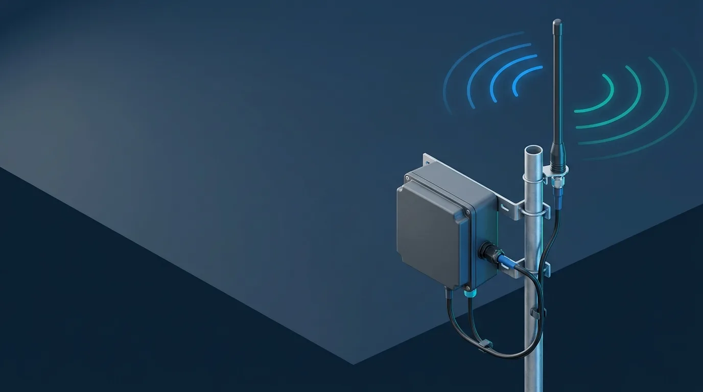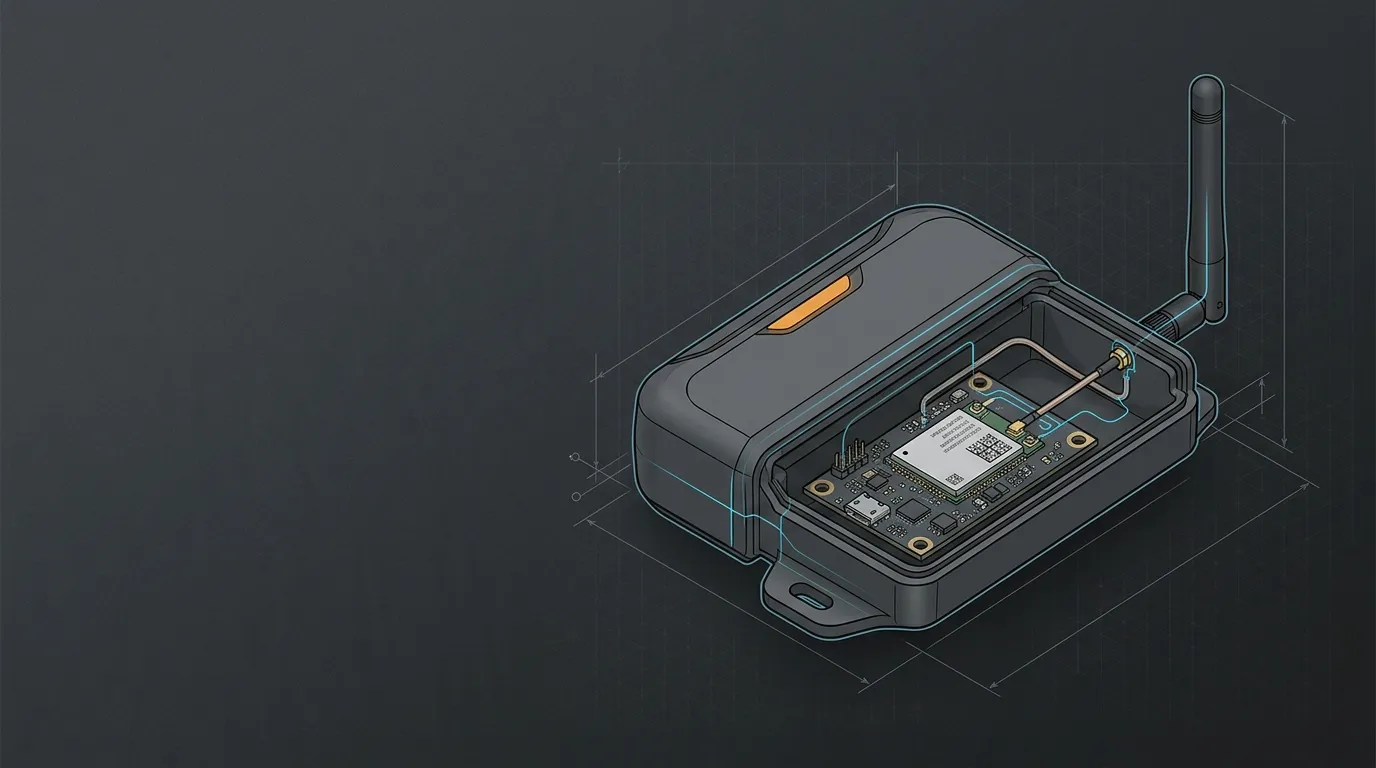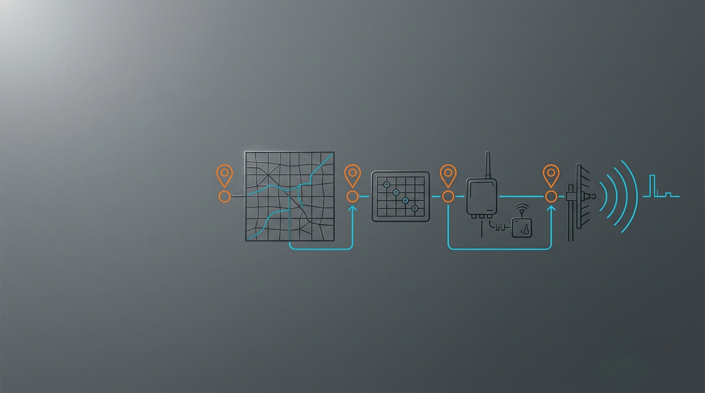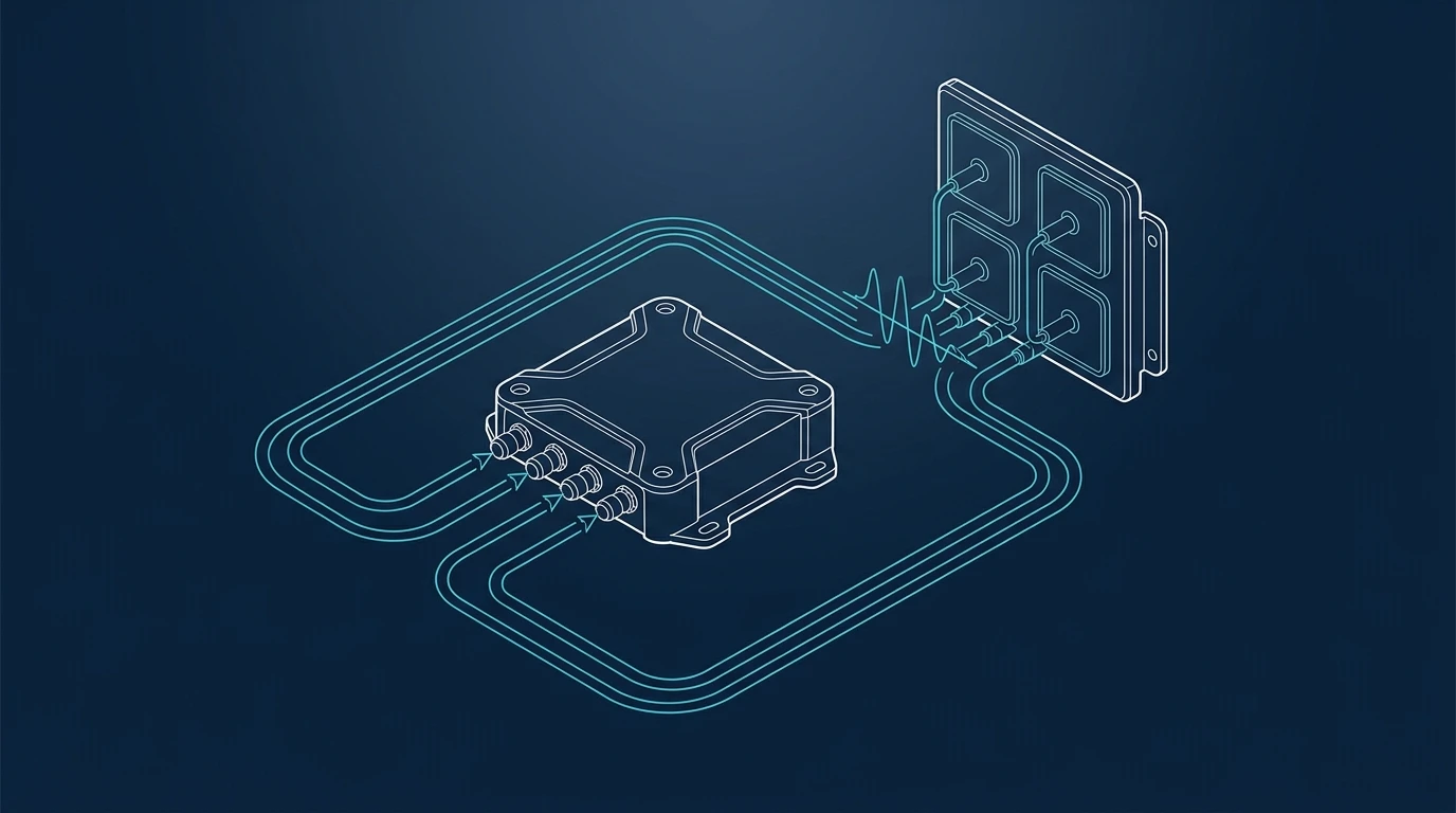
A 2x2 4x4 MIMO antenna placement decision starts with the router’s documented active RF chains, not with a generic antenna count or a fixed spacing rule. A 2x2 radio needs its documented two compatible paths; a 4x4 radio needs its documented four. Map every port, band, lead and mounting condition, then compare the installed system with a controlled baseline before calling the installation complete.
If the radio, active bands or deployment objective are not yet documented, begin with the radio-first IoT antenna selection workflow before choosing a 2x2 or 4x4 assembly.
The direct answer: match the active radio paths, not the marketing label
2x2 and 4x4 describe a radio arrangement: two or four transmit/receive paths are available to the relevant radio under the device’s supported configuration. They do not mean that adding two or four visually similar antennas will automatically enable a particular mode or produce a predictable speed, range or signal improvement.
For an industrial cellular router, begin with the exact model, hardware variant and manual. Its connectors can belong to cellular, Wi-Fi, GNSS or another radio. Only the documentation for that variant can tell you which external ports are active, which are paired, and whether a particular modem or band configuration uses two or four paths.
| Installation question | 2x2 starting point | 4x4 starting point |
|---|---|---|
| What must be present? | The two documented active RF paths and compatible antenna connection(s). | The four documented active RF paths and compatible antenna connection(s). |
| What may the antenna look like? | Two single-element antennas or an approved two-path assembly. | Four single-element antennas or an approved four-path, multi-element assembly. |
| What must not be assumed? | That MAIN alone represents the complete MIMO installation. | That four connectors are interchangeable, or that four independent whips equal an engineered 4x4 assembly. |
| How is success established? | The documented configuration and a repeatable final-installation test. | The documented configuration and a repeatable final-installation test. |
Some routers identify a modem pair as MAIN0 and AUX0, then a second pair as MAIN1 and AUX1; another model can use entirely different labels. For example, Cradlepoint’s IBR1700 guidance calls out sequential antenna-lead pairs and modem connection pairs, while also directing the installer to confirm the specific antenna manufacturer’s mapping. That is a useful example of why a port map comes before an installation diagram: review its antenna connection guidance, then follow the documents for the actual device and assembly being deployed.
If you are still deciding whether an external cellular assembly is appropriate at all, first separate the cellular WAN from local Wi-Fi coverage with this 4G/5G router antenna selection guide. A better cellular antenna path will not repair a Wi-Fi coverage design problem.
Build a port map before selecting or mounting anything
Create one installation record for each router model and site. Do not use a product photo, a connector count, or the manual for a similar model as the source of truth.
| Record | Capture from the exact documentation or installation | Why it matters |
|---|---|---|
| Device identity | Model, hardware revision, modem option and firmware/configuration where relevant | Port functions and supported MIMO modes can change across variants. |
| Radio and service | Cellular versus Wi-Fi versus GNSS, carrier/region, active bands and operating mode | An antenna must cover the radio and bands that the router is actually using. |
| Port map | Every RF port label, function, connector family and mating gender | Prevents a cellular lead being routed to a Wi-Fi or GNSS interface. |
| Required paths | The active chain count, documented pairing and any unused-port treatment | Turns “2x2” or “4x4” into an auditable installation requirement. |
| Antenna assembly | Part number, number of elements/leads, lead labels, bands, intended orientation and mount instructions | A multi-element radome is an RF system, not a bag of interchangeable cables. |
| Feed path | Cable family, length, both connector ends, adapters, bulkheads and route | Makes losses, adapters and later field changes visible. |
| Site envelope | Indoor/outdoor, enclosure material, mount position, ingress route, service access and safety constraints | Placement must survive the actual installation, not only a bench test. |
For connector checks, record both the family and mating gender; “SMA-compatible” alone is not enough. Use the SMA vs RP-SMA connector guide to make the record explicit, then confirm the router and antenna data sheets before ordering an adapter. A mechanically similar connector on the wrong radio or with the wrong gender is still the wrong path.
Translate the port map into a 2x2 or 4x4 installation
Once the port map exists, make the route from each router port to its intended antenna element unambiguous. Number the paths in the work order, on the assembly drawing and, where service practice permits, on the leads. Do not invent pairing based on the physical order of the connectors.
For a 2x2 router or radio
Confirm the following before installing:
- The exact modem/radio configuration documents two active paths for the use case.
- Both documented ports are connected to compatible antenna paths; a single connected primary path is not a substitute for a complete 2x2 installation.
- The antenna or two-antenna arrangement covers the active bands and follows its own mounting and polarization instructions.
- Both cable routes, connector ends and adapters are recorded so later comparisons stay meaningful.
For a 4x4 router or radio
A 4x4 installation adds two more paths, but it also increases the chance of a mapping or feed-path error. Confirm all of the 2x2 checks, then add:
- The documented four active ports and any specified port pairs.
- A four-path antenna system or four discrete paths that the router and antenna documentation support for this arrangement.
- The lead-to-port mapping supplied for that assembly. Do not treat four labelled leads as four interchangeable extensions.
- A mounting design that preserves the assembly’s specified polarization, orientation, cable bend limits and service access.
Cisco’s industrial antenna guidance makes the wider principle clear: populate suitable antenna paths for multiple RF ports, but treat an integrated multi-element antenna as an engineered design with its own diversity, polarization and isolation characteristics. It also notes that equipment-mounted antennas and crowded cabling can affect an installation. See the Cisco industrial router antenna guide as general context—not as a replacement for your router’s model-specific port assignment.
Place the antenna system according to the assembly and the site
Physical placement is a design decision involving the antenna assembly, operating bands, cabinet or vehicle geometry, cable route and the intended service environment. It is not a universal recipe such as “put every 4x4 antenna at one angle” or “use one separation value for every installation.” A compact, engineered four-path panel can have different internal geometry from four separate external elements; a router’s own installation guide can also state requirements that apply only to that chassis and radio.
Use the manufacturer’s instructions for the chosen assembly as the first authority for orientation, polarization, lead mapping, required clearances, mounting surface and any separation guidance. Then check the proposed site:
| Site condition | Placement decision to document | What to verify before release |
|---|---|---|
| Router in a metal cabinet | Whether the antenna is external, how the bulkhead/feed-through is made, and whether the design expects a conductive reference surface | Cabinet material/coating, entry sealing, cable strain relief and the final antenna geometry. |
| Fixed building or infrastructure site | Where the antenna sees the intended service area or serving network, and how it will be maintained | Mount rigidity, route, weather protection, service access and the repeatable test points. |
| Vehicle or mobile equipment | The approved mounting surface, orientation and a cable route that tolerates motion and service | Surface compatibility, ingress, vibration/strain relief and safety documentation. |
| Router with Wi-Fi and cellular antennas nearby | Which antennas belong to each radio and the device-specific layout | Manual diagrams, assembly instructions and the absence of conflicting cable routes. |
When a cabinet is involved, do not assume that metal is always helpful or always harmful. It can change the installed antenna system, obscure useful directions or create a different feed-path problem. The metal-enclosure antenna guide explains how to record those effects and compare the final geometry with a baseline.
For a fixed router, it is often more useful to preserve a clear, serviceable external location and a known cable path than to optimize one isolated number on a data sheet. For mobile equipment, the appropriate form factor and mount method change again; use the magnetic-mount versus permanent-mount comparison for the mechanical decision, then return to the port map before connecting any lead.
Keep every RF path comparable
An apparent 2x2-versus-4x4 result can really be a difference in cable length, an added adapter, a changed bulkhead, a misplaced lead or a different operating band. Protect the comparison by documenting each path end to end.
| Path ID | Router port | Antenna lead/element | Cable and length | Interfaces | Route and mount observation |
|---|---|---|---|---|---|
| Path 1 | Copy the documented port label | Copy the assembly lead label | Family and measured/ordered length | Both mating ends and every adapter | Entry point, strain relief and any nearby obstruction |
| Path 2 | Copy the documented port label | Copy the assembly lead label | Family and measured/ordered length | Both mating ends and every adapter | Entry point, strain relief and any nearby obstruction |
| Path 3, if used | Copy the documented port label | Copy the assembly lead label | Family and measured/ordered length | Both mating ends and every adapter | Entry point, strain relief and any nearby obstruction |
| Path 4, if used | Copy the documented port label | Copy the assembly lead label | Family and measured/ordered length | Both mating ends and every adapter | Entry point, strain relief and any nearby obstruction |
Keep cable differences intentional and visible. A longer or different cable route can consume margin independently of the antenna element. The IoT link-budget and cable-loss guide provides the calculation framework; use the actual frequency and the cable maker’s published loss data rather than a generic loss estimate.
Commission the final system with a controlled test
The purpose of commissioning is not to prove a universal 4x4 benefit. It is to decide whether this router, this radio configuration and this final installed assembly meet the project’s acceptance criteria. Establish a baseline first, then change one documented variable at a time where practical.
| Test record | Keep stable or record | Example decision use |
|---|---|---|
| Router state | Exact model/firmware, modem settings, SIM/service, active bands and radio mode | Avoid comparing two different radio configurations. |
| Antenna path | Assembly part number, lead mapping, cable assemblies, adapters and mount geometry | Identify whether a result belongs to the antenna or feed path. |
| Test method | Same representative endpoints or route, traffic/message pattern and observation window | Make a before/after observation comparable. |
| Observables | Device-reported signal/link-quality indicators, registered band/cell where available, application result and exceptions | Use the measures relevant to the project instead of one headline metric. |
| Action | Keep, remap a lead, inspect a connector/cable, reposition under approved guidance, or escalate | Leaves the next technician a reproducible decision trail. |
If the router exposes cellular indicators such as received level, quality or SINR, record the conditions alongside them rather than treating one reading as a guarantee of user experience. The same discipline applies to application tests: keep endpoints and traffic behaviour representative, record exceptions, and avoid calling an installation “better” simply because one momentary reading changed.
Before sign-off, revisit the external antenna compatibility checklist. It is a practical final pass for radio, bands, MIMO paths, interfaces, mounting environment and test record—the items most likely to turn a correct-looking purchase into an incomplete deployment.
Send an engineering-ready request for quote or support record
When asking a supplier to recommend a 2x2 or 4x4 solution, “router needs an antenna” is too little information. Send the structured record below so the response can be checked against the device and site.
| Include in the request | Why the engineering team needs it |
|---|---|
| Exact router model, hardware variant and current port-map source | Confirms which connectors and MIMO paths belong to which radio. |
| Country/carrier where applicable, active bands and intended radio service | Establishes the required frequency coverage. |
| Required 2x2 or 4x4 mode, active port labels and any documented pairs | Avoids an incomplete lead count or incorrect routing. |
| Photos/drawing of the enclosure, mount location and cable entry | Reveals mechanical, detuning, ingress and service constraints early. |
| Desired antenna form factor and environmental requirements | Narrows panel, omni, low-profile or remote-mount options responsibly. |
| Planned cable lengths, connector ends and adapter/bulkhead constraints | Lets the supplier specify an end-to-end assembly rather than a loose antenna. |
| Baseline observations and acceptance method | Defines what the installed system will be compared against. |
GNSource can review that record and help match an antenna assembly and cable set to the documented router paths. Contact our engineering team with the port map, active bands, installation photos and test objective; do not rely on a MIMO label alone.
Frequently asked questions
Can I turn a 2x2 router into 4x4 by adding two antennas?
Not unless the exact router and active modem configuration document four supported external RF paths for the relevant radio. Antennas cannot create additional radio chains that the device does not provide. Confirm the model-specific port map and supported mode first.
Does a 4x4 router always need four separate antenna housings?
No. Some installations use an approved multi-element assembly with multiple labelled leads under one radome, while others use separate elements. The decision is the specified four RF paths, supported bands and installation instructions—not the number of visible housings.
What is the correct spacing and angle for 4x4 MIMO antennas?
Use the instructions for the exact antenna assembly and router. Geometry depends on frequency range, antenna type, polarization, whether elements share a radome, the chassis and the surrounding structure. A number copied from a different product can make the installation less repeatable, not more reliable.
Why did a 4x4 installation not show a consistent improvement in a field check?
The observed result can depend on the active network and band, radio configuration, port mapping, antenna and cable paths, mounting environment and test method. First verify every documented path and compare the final system against a controlled baseline; then use the record to decide whether the next issue is placement, a feed-path error or the wider network environment.