External antenna compatibility is not established by a connector that happens to screw onto a device. A compatible installation needs a documented external radio path, the right operating bands, every required antenna port and RF chain, the correct mating interface, a suitable cable and installation path, and a way to validate the result. If any one of those facts is unknown, pause the order and check the exact device documentation.
This checklist is designed for industrial IoT routers, LoRaWAN gateways, Wi-Fi equipment and similar multi-radio devices. It turns a broad compatibility question into an engineering record that a supplier can review. Start with the radio-first IoT antenna selection workflow if the radio technology and deployment objective have not yet been defined.
First, confirm that the device supports an external antenna path
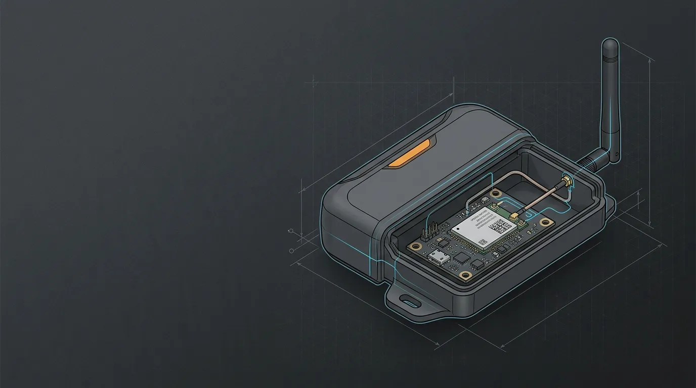
An antenna cannot be made compatible by an adapter when the device has no documented external antenna port or no manufacturer-supported external-antenna option. A hidden board connector, an enclosure modification or a third-party cable may change the RF path, mechanical integrity or device configuration in ways that a generic antenna specification cannot verify.
Collect the exact device model, hardware revision, region variant and firmware version first. Then find the manual, data sheet or approved-antenna matrix that identifies each radio port. Manufacturer matrices are useful evidence for this gate: for example, the Extreme Networks antenna compatibility matrix maps particular antennas and adapters to named access-point models and ports. It is not a universal matrix for other radios, but it illustrates the level of model-specific evidence to look for.
If the manual does not identify an external radio path, record that result as “not confirmed.” Do not convert it into “probably compatible.”
The seven checks for external antenna compatibility
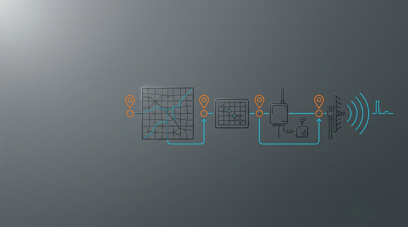
Use this table as a stop/go worksheet. The rows are ordered so that a missing device fact stops the process before a buyer spends time comparing antenna gain or form factor.
| Check | What to record from the device and antenna documents | Stop or proceed rule |
|---|---|---|
| 1. Device and approved path | Exact model, region/revision, firmware, port label and any approved-antenna requirement | Stop if the external path or port function is not documented. |
| 2. Radio and bands | Radio function plus the exact operating bands/channels for this variant | Stop if an antenna’s published band coverage does not include the active radio bands. |
| 3. Port and RF-chain count | MAIN/AUX/DIV labels, Wi-Fi ports, 2x2 or 4x4 MIMO requirement, and every active lead | Stop if the proposal leaves a required chain unused or connects an antenna to a different radio. |
| 4. Mating interface | Connector family, thread/body and center-contact observations at both ends | Stop if the direct mate is unknown; a thread fit alone is insufficient. |
| 5. Antenna function | Frequency coverage, pattern, polarization, mounting orientation and installation role | Stop if the antenna was specified for a different radio, band or coverage objective. |
| 6. Cable and adapter path | Coax family, length, both ends, bulkheads/adapters and documented loss where available | Stop if an added path is unspecified or its practical loss/strain/environment is unknown. |
| 7. Installation and validation | Mounting surface, indoor/outdoor route, ingress constraints, configuration requirement and acceptance test | Proceed only with a defined install and a result you can compare with a baseline. |
This is an antenna port compatibility process, not a promise that one specification works across every device in the same product family. A revision or regional variant can expose different bands, connectors or software controls.
Match the radio and operating bands before choosing an antenna
“IoT” is not a radio band. A cellular router, a LoRaWAN gateway and a Wi-Fi access point can sit in the same enclosure class while needing different antenna paths.
- Cellular: confirm the regional LTE or 5G bands used by the modem, then identify which ports are cellular rather than Wi-Fi or GNSS. A multi-band antenna must cover the actual modem bands, not merely carry a “4G” or “5G” label.
- LoRaWAN: confirm the deployed regional plan and the module/gateway configuration before selecting a sub-GHz antenna. The regional LoRaWAN band verification guide explains why 868 MHz and 915 MHz are not interchangeable labels.
- Wi-Fi: identify whether the port serves 2.4 GHz, 5 GHz or 6 GHz operation and whether the radio uses multiple chains. Use the tri-band Wi-Fi external antenna checks when the device includes Wi-Fi 6E.
This is the practical meaning of antenna frequency compatibility: the antenna specification must cover the radio’s documented operating range with the intended pattern and installation, rather than just overlap one familiar frequency number.
Count ports before deciding that one antenna is enough
External ports often look alike while serving different functions. A cellular router may expose cellular MAIN and AUX/DIV or multiple MIMO ports beside separate Wi-Fi and GNSS ports. A Wi-Fi device can require one antenna per chain. Replacing several required paths with one convenient antenna can leave the installation incomplete even if every connector is mechanically valid.
Create a port map with the port label, radio function, connector interface and required chain count. For a router example, see cellular router ports and MIMO paths. The point is not that every device needs the same number of antennas; it is that the data sheet, not the number of visible connectors, determines the required RF paths.
Where the device vendor requires an antenna profile, gain entry or other radio configuration, include that setting in the worksheet. Fortinet’s external-antenna guidance is a Wi-Fi-specific example of why a physical connection can have a configuration dependency. Apply such a setting only when the documentation for the exact device calls for it.
Check the whole feed path, not just the connector
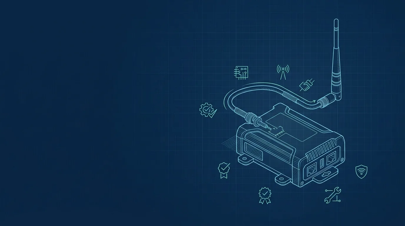
Antenna connector compatibility is one gate inside the system, not the final answer. First identify the interface family and both mating faces. In particular, SMA and RP-SMA can look similar while reversing the center pin/socket convention. Use the dedicated guide to identify the SMA or RP-SMA mating interface before specifying an adapter or cable assembly.
An adapter is appropriate only after both actual ends and the intended radio port are known. It may bridge a known interface mismatch; it cannot make a Wi-Fi antenna suitable for a cellular port, add missing MIMO paths, create band coverage or validate an undocumented device port.
Then document the complete cable route: coax type, length, both end types, any bulkhead, every adapter, bend/strain constraints and whether the route is indoor or exposed. A longer or more complex path can consume useful margin. Use the link-budget process to account for cable loss and link margin rather than assuming an antenna gain figure cancels every added loss.
Turn the checklist into a supplier-ready record
A useful RFQ does not need every value to be known. It needs unknowns labeled clearly enough that an engineer can request the right document or reject an unsafe assumption. Send the following record with close-up port photos when the connector designation is uncertain.
| RFQ field | Minimum useful detail |
|---|---|
| Device | Manufacturer, exact model, hardware/region variant and firmware |
| Radio path | Port labels and functions: cellular, Wi-Fi, LoRaWAN, GNSS or other documented service |
| Bands and chains | Active bands/channels, MIMO/diversity count and all required ports |
| Interface | Manufacturer connector designation, or thread/body plus center-contact observations at both ends |
| Antenna target | Required coverage, pattern/polarization, mounting orientation and indoor/outdoor location |
| Feed assembly | Coax type and length, both connectors, adapters/bulkheads and environmental route |
| Configuration and test | Required device setting, baseline metric, acceptance metric and test location/conditions |
For the acceptance test, use the same device, operating mode, site and representative traffic or telemetry condition before and after the installation. Compare the metric that matters for that radio—such as a documented received-level, link-quality or connection-stability measure—rather than promising a universal range increase. Keep the completed record with the installation so the antenna path can be reproduced or reviewed later.
Frequently asked questions
Can I use any external antenna that fits the connector?
No. A fitting connector only suggests that one mechanical interface may mate. You still need the device’s approved external path, correct radio port, operating bands, chain count, cable path and installation conditions to agree.
What if my IoT device has no external antenna port?
Treat it as a device-design or vendor-support question, not a normal antenna-adapter choice. Do not assume a hidden board connector or enclosure modification creates a validated external RF path.
Can an adapter make an antenna compatible?
Only with a known connector-interface mismatch. It cannot change the radio function, extend an antenna’s frequency coverage, replace required MIMO paths or establish that the device supports an external antenna.
How do I validate an external antenna installation?
Record the device variant, port map, antenna and cable assembly, mounting location, configuration and a baseline measurement. Install the documented assembly, then repeat the same test conditions and retain the result with the RFQ or support record.
An honest “unknown” is more useful than a guessed compatibility claim. Once the seven checks are complete, contact GNSource Engineering with the record for an antenna, cable-assembly or installation-specification review.