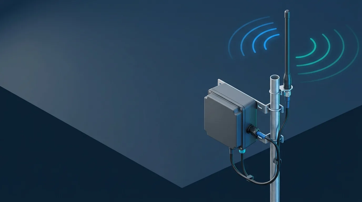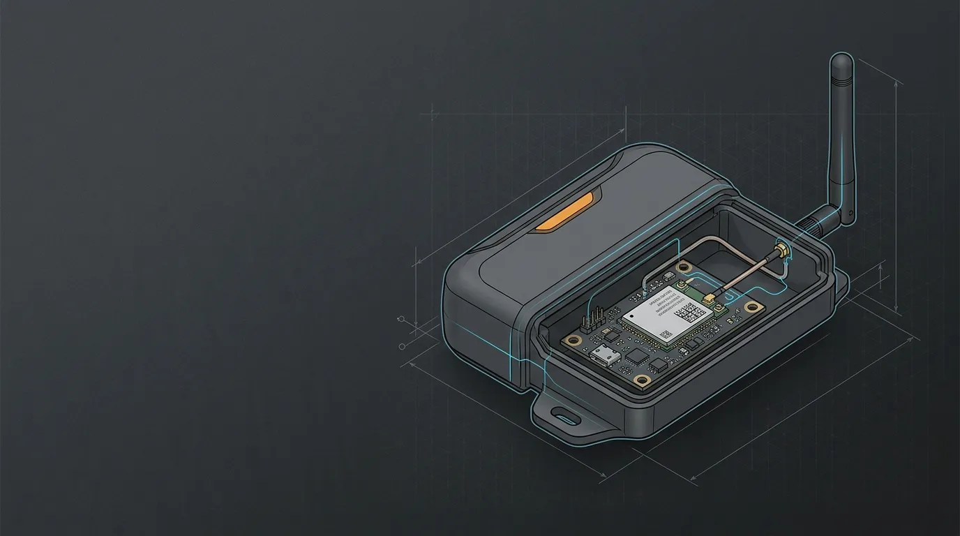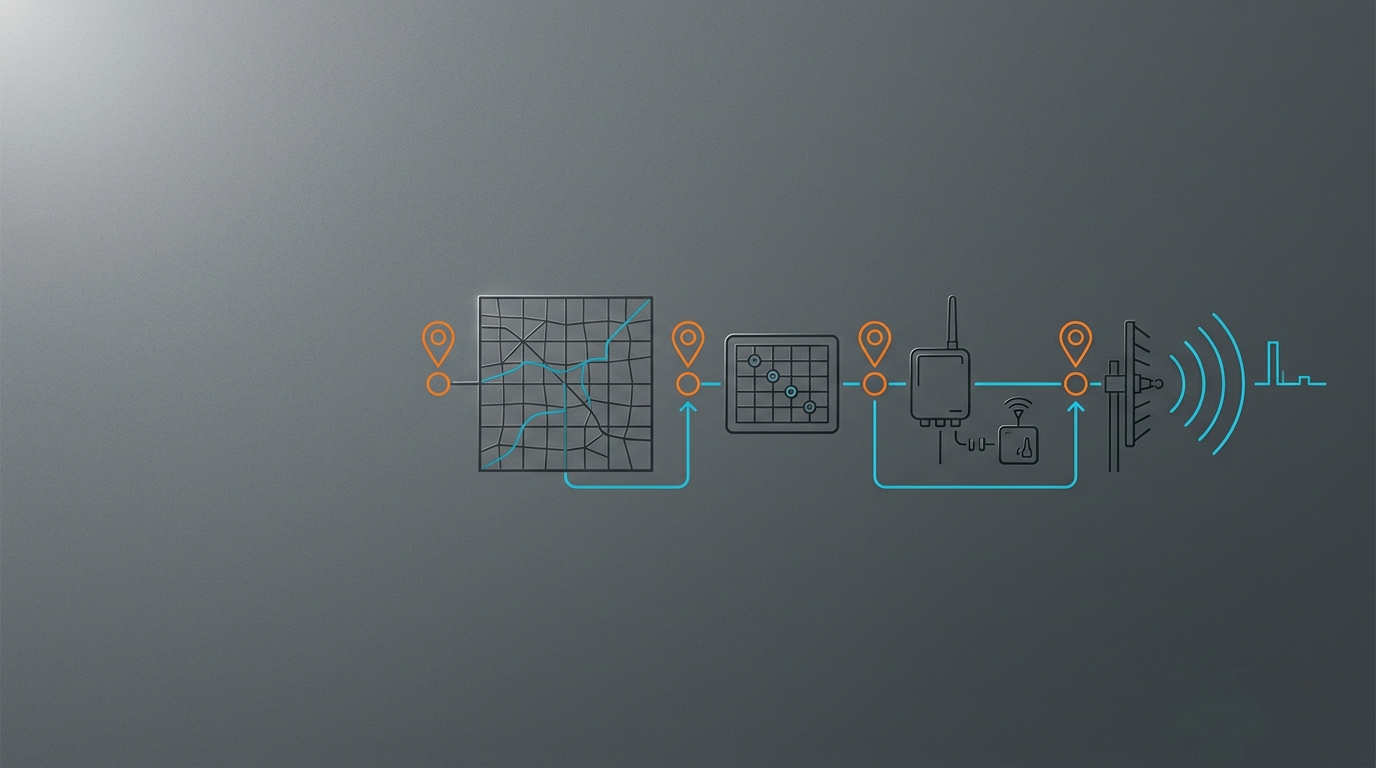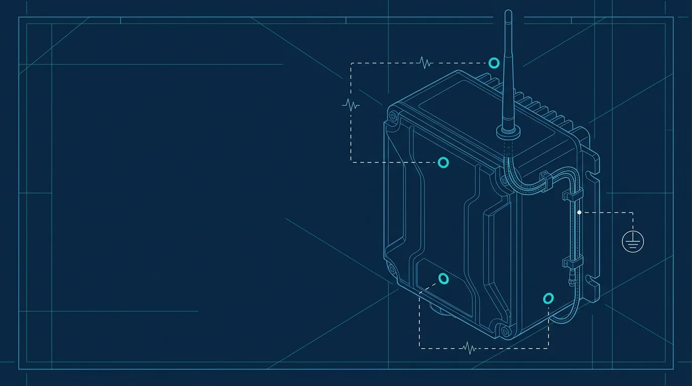
An antenna near a metal enclosure is not automatically a problem or an upgrade. Metal can be an intended conductive reference for one antenna design, while the same enclosure can detune another antenna, block part of its pattern or alter the installed feed path. Treat the enclosure, antenna, mount and cable as one RF assembly, then compare a documented baseline with the final installation.
This guide is for industrial IoT devices, routers and gateways with an external antenna near a cabinet, panel or vehicle surface. It does not prescribe a universal enclosure size, clearance, dB improvement or modification. Start with the radio-first IoT antenna selection framework if the radio, bands and deployment objective are not yet documented.
Four ways metal can change an installed antenna
Metal has different effects that should not be collapsed into the phrase “ground plane.”
| Mechanism | What it can mean | What to verify before acting |
|---|---|---|
| Intended conductive reference | Some antenna and mount designs expect a conductive reference surface or counterpoise. | Check the antenna and device documentation for the required mounting arrangement. |
| Near-field detuning | Nearby conductive material can change the antenna’s installed match and behaviour. | Keep the exact antenna, mount position, enclosure material and clearance in the test record. |
| Pattern blockage or shadowing | A cabinet, roofline or panel can reduce useful exposure in some directions. | Compare representative endpoint locations, not a single reading beside the gateway. |
| Feed-path change | A new bulkhead, adapter, cable length or routing can consume margin independently of the antenna element. | Record both cable ends, length, adapters and strain/entry path. |
The practical rule is simple: metal may help only where the antenna system was designed and installed to use it. A random metal box is not automatically a suitable reference surface, and a nonconductive surface is not automatically a defect.
Start with the antenna and enclosure facts
Before moving an antenna, collect the exact device variant, radio port, active bands, antenna model, connector interface, cable assembly and enclosure material/finish. Include the mount type: magnetic base, direct bulkhead, bracket, adhesive or a purpose-designed external assembly.
For a system-level record, use the external antenna compatibility checklist. If the question is whether a magnetic base or a mechanically fixed mount fits the surface and service plan, continue with magnetic mount versus permanent mount. Do not cut an enclosure or change a certified assembly based only on a generic online mounting tip.
Use a controlled comparison instead of a universal rule
The most useful validation keeps the radio, configuration, antenna type, cable assembly and test endpoints stable while changing one documented installation variable. For example, compare the proposed enclosure position with a known baseline position, then repeat the same representative endpoint test routes.
| Test record | What to hold or record |
|---|---|
| Radio system | Device model/firmware, active band, port and power/configuration state |
| Antenna path | Antenna model, mount, cable family/length, connectors and adapters |
| Enclosure condition | Material, coating, relevant dimensions, nearby metal and final mount position |
| Test method | Same endpoints or routes, message pattern, time window and backhaul state |
| Result | The system’s available received-level, link-quality or packet-delivery observation plus exceptions |
| Next action | Keep, reposition, review the feed path or escalate to the antenna/device engineering owner |
This approach does not turn one project result into a general antenna rating. It makes a decision auditable and shows whether the next issue is likely placement, feed loss, port mapping or the wider radio environment.
Check the feed path before blaming the enclosure
An installation change often adds cable length, a bulkhead or an adapter at the same time as it moves the antenna. That makes it easy to assign a feed-path loss to the metal enclosure. Record every added interface and use an IoT link-budget and cable-loss check at the actual operating band before drawing a conclusion.
Likewise, a multi-port router requires each active chain to retain its documented antenna path. A better single-antenna test does not replace a missing MIMO lead. See the router guide’s MIMO and port-map checks before treating a different enclosure location as the complete fix.
Send an engineering-ready handoff record
When a result needs review, send the enclosure facts and test record rather than “signal got worse near metal.” Include the device and radio, antenna and cable assembly, enclosure material/coating, mount method, photos of the final geometry, baseline/final observations and any remaining unknowns. That allows an engineering team or supplier to identify which document, measurement or controlled change is needed next.
Frequently asked questions
Does a metal enclosure always improve antenna performance?
No. Some designs use a conductive reference surface; others can detune or be blocked by nearby metal. Check the intended antenna installation and validate the final assembly.
How far should an antenna be from metal?
There is no universal clearance that applies across bands, antenna types and enclosures. Follow the applicable antenna/device documentation, then test the completed installation against a controlled baseline.
Can I add a longer cable to move the antenna away from the enclosure?
Possibly, but the added cable and interfaces become part of the RF trade-off. Record their loss and installation constraints before assuming relocation improves the link.
What should I give an antenna supplier for review?
Provide the device/port/band information, antenna and cable assembly, enclosure material and mount geometry, photos, and comparable baseline/final observations. Contact GNSource Engineering with that record for an installation-specification review.