An SMA vs RP-SMA antenna connector decision comes down to two separate observations: the threaded coupling on the outside and the center contact inside. Standard SMA and reverse-polarity SMA can look nearly identical, but RP-SMA swaps the center pin/socket convention. A direct connection needs both features to agree. If the threads will engage but the center contacts are both pins or both sockets, stop—do not force the connector or assume an antenna is compatible.
That mechanical check is only the first gate. A correct mate still has to belong on the right RF port, cover the radio’s operating band, use the required cable path and preserve every required MIMO chain. This guide gives the connector-identification step first, then shows how to turn it into a usable antenna or cable specification.
SMA vs RP-SMA: the direct answer
SMA and RP-SMA are related threaded RF connector interfaces, but they are not interchangeable direct mates. In standard SMA, a connector with internal threads normally has a center pin, while a connector with external threads has a center socket. RP-SMA keeps the threaded shells familiar but reverses the center-contact convention. That is why a label or a distant product photo is not enough to select an antenna.
The word reverse polarity here describes the connector’s center-contact arrangement. It does not tell you the antenna’s RF polarization, frequency coverage, gain, or whether it belongs to Wi-Fi, cellular or GNSS. Those are separate system facts.
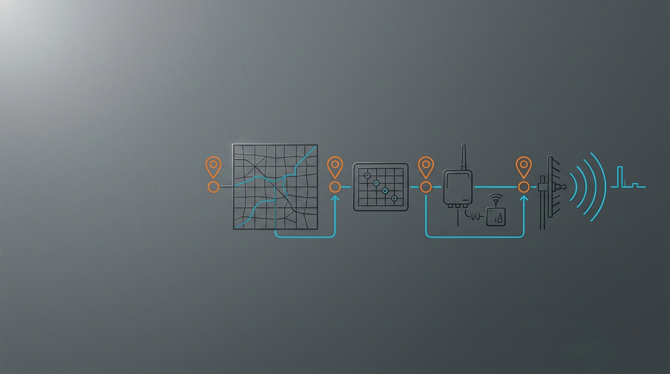
For a broader decision path after the connector is identified, use the IoT antenna selection workflow. It starts with the radio and operating band rather than treating the connector as the whole antenna specification.
Identify the threads and center contact separately
Inspect the device-side port and the antenna or cable plug as two separate parts. Use a clear close-up photo, the exact device manual or an assembly drawing; do not identify an RF interface from a listing title alone.
Start with the coupling body:
- Internal thread means the threaded surface is inside the coupling nut or shell.
- External thread means the threaded surface is visible on the outside of the port or connector body.
Then look at the center contact:
- A pin is a projecting center conductor.
- A socket or receptacle is a center opening designed to receive a pin.
Do not let one observation stand in for the other. With SMA-family interfaces, the shell convention and center-contact convention are paired differently in standard SMA and RP-SMA. A connector can therefore have the thread pattern you expected while still presenting the wrong center contact.
The naming can feel counterintuitive because connector gender follows the interface convention, not a rule such as “a visible pin is always male.” Record the complete manufacturer designation if the manual provides it. If it does not, record the two visible observations—thread position and center contact—and ask for the intended mating end in writing.
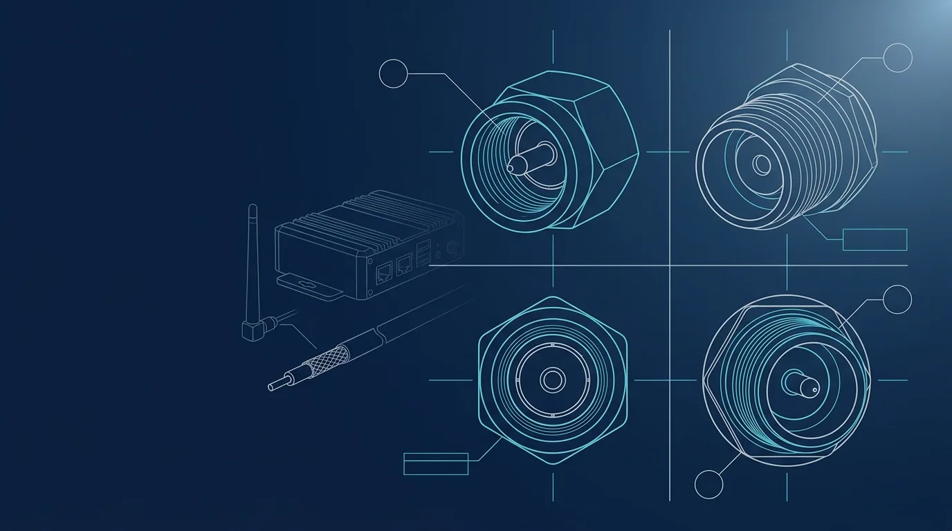
The four connector faces and their direct mates
This matrix is a buying and inspection aid, not a substitute for the exact device drawing. “Direct mate” means the paired connector in the same interface family, with the matching threads and opposite center contact.
| Connector face | Thread/body cue | Centre contact | Direct mate | What a mismatch can look like |
|---|---|---|---|---|
| SMA male | Internal thread | Pin | SMA female | It may resemble an RP-SMA male from the outside, but the center pin changes the mate. |
| SMA female | External thread | Socket | SMA male | It can thread onto an RP-SMA male body, but two sockets do not make a working center contact. |
| RP-SMA male | Internal thread | Socket | RP-SMA female | It can look like an SMA male at a glance; inspect the center before ordering. |
| RP-SMA female | External thread | Pin | RP-SMA male | It can thread onto an SMA male body, but two pins are not a valid electrical mate. |
The two confusing combinations are the reason to inspect the center contact after the threads. An SMA male and an RP-SMA female may appear to couple mechanically but bring two pins together. An SMA female and an RP-SMA male can present two sockets. Neither is a valid direct connection.
One router maker’s installation documentation makes the distinction concrete: on selected GL.iNet hardware, Wi-Fi antennas use an RP-SMA female base with external threads and an internal pin, while 5G NR antennas use an SMA female base with external threads and an internal hole. The required antenna ends are different even though both ports present external threads. See its external-antenna installation guide for that device-specific example.
Where the port is used for Wi-Fi, continue with the Wi-Fi 6E external antenna port guide. The interface check does not replace the separate band, channel and MIMO checks for that radio.
Reverse polarity is not RF polarization
“RP” is easy to misread as a radiation-property claim. It is not. An antenna’s RF polarization is its electromagnetic field orientation—such as linear vertical, linear horizontal, or circular—not the pin/socket arrangement of the connector at its feed.
Likewise, an RP-SMA label does not establish a frequency range, a 50-ohm system match in the finished installation, or an antenna pattern. A Fairview Microwave RP-SMA connector specification is one example of a 50-ohm RF interconnect component; the interface family alone does not identify which antenna element, cable loss or radio port is appropriate for a particular deployment.
Treat connector compatibility as a necessary mechanical and electrical-contact condition. Treat antenna selection as a separate radio-system decision.
Verify the device port before choosing an antenna
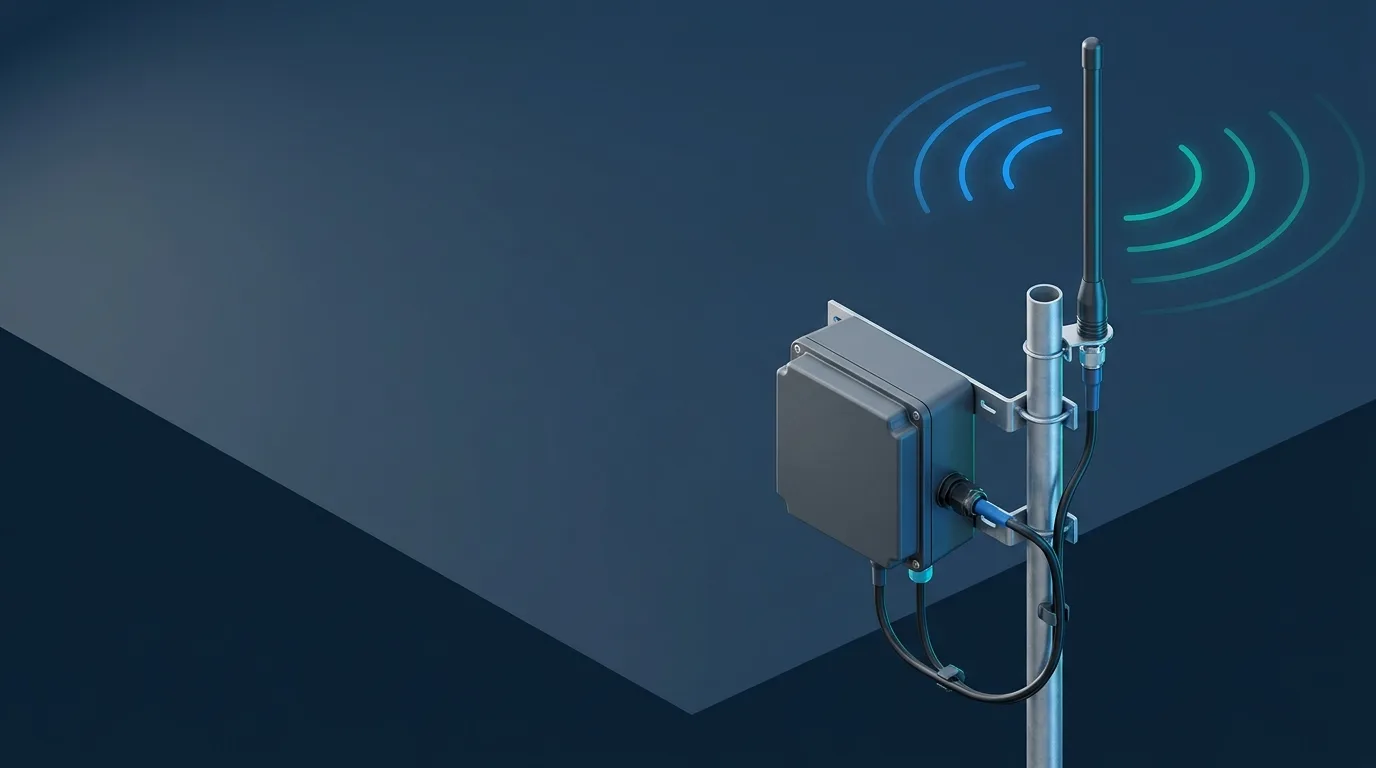
An enclosure can expose several antenna connectors that serve different radios. A single industrial router may have Wi-Fi, cellular and GNSS ports, each with a different connector family or a visually similar one. Connecting a mechanically compatible antenna to the wrong port does not make it an appropriate antenna.
Build a one-page port map from the exact model’s manual:
| Field | What to record | Why it matters |
|---|---|---|
| Device and variant | Exact model, region and hardware revision | A similar-looking version may use different ports or bands. |
| Port label and function | Wi-Fi, cellular MAIN/DIV/MIMO, GNSS, BLE or other documented radio | Connector family does not identify the radio function. |
| Device-side interface | SMA/RP-SMA or other family, plus thread and center-contact observations | Defines the required mating end. |
| Antenna requirement | Operating bands, polarization/pattern and indoor or outdoor placement | A mating connector does not prove RF suitability. |
| RF-chain count | Single chain, 2x2 or 4x4 MIMO, with port labels | Each active chain needs the approved path; one antenna does not replace a multi-port system. |
| Cable assembly | Coax type, length, both ends, any bulkhead or adapter and environmental route | The finished path can add loss, strain and weather-entry risk. |
For cellular routers, a router cellular-port verification checklist shows why cellular, Wi-Fi and GNSS connectors must be mapped before buying. After a cellular port is confirmed, use the LTE antenna band and placement checks to verify the radio and installation rather than relying on a connector fit.
When an adapter is appropriate
An adapter is appropriate only when you have identified both actual mating ends and know that the antenna belongs to the intended port. It can solve a known SMA-to-RP-SMA interface mismatch; it cannot convert a Wi-Fi antenna into a cellular antenna, add missing MIMO paths, widen an antenna’s frequency response or validate an unknown port.
Before putting an adapter into a production cable path, confirm:
- The device port’s radio function and the antenna’s intended radio function agree.
- The adapter specifies the two required interface ends, not merely a vague “SMA/RP-SMA” title.
- The full assembly follows the radio’s impedance and cable requirements.
- Every required MIMO lead has its own correct, documented path.
- Added length, adapters, bulkheads and strain relief are acceptable for the installation.
- Outdoor entries still meet the enclosure and sealing requirements after the adapter is introduced.
The engineering trade-off is not “adapters are always bad.” It is whether a known interface conversion is worth the extra interface in a particular assembly. Account for the added parts in the cable and connector loss in the link budget instead of assuming that a correct mate has no system cost.
Put the right connector facts in an RFQ
The most useful antenna or cable RFQ is precise enough that a supplier can reject an incompatible mating end before samples are made. Include this information:
| RFQ field | What to send |
|---|---|
| Device | Exact manufacturer model, variant and region |
| Radio port | The label and documented function, such as Wi-Fi 1, cellular MAIN or GNSS |
| Device-side connector | The manual’s connector designation; if unknown, close-up photos plus thread/body and center-contact observations |
| Required mating end | The antenna or cable connector expected to mate directly, or the approved adapter path |
| RF requirement | Bands/channels, radio technology and active MIMO-chain count |
| Cable assembly | Coax family, length, both terminations, bulkheads and any adapter |
| Installation | Indoor/outdoor setting, mounting, enclosure entry, bend/strain constraints and quantity |
“Unknown” is a valid RFQ value when it is accompanied by the device model and clear photos. Guessing is not. Once the interface and radio path are confirmed, you can compare whip antenna options for connected devices or ask GNSource Engineering to review a complete antenna or cable-assembly specification.
Frequently asked questions
Are SMA and RP-SMA the same?
No. They are related threaded connector families, but RP-SMA reverses the center pin/socket convention relative to standard SMA. The labels and both connector faces must be checked before treating two parts as direct mates.
Are SMA and RP-SMA directly compatible?
No. A standard SMA male directly mates with a standard SMA female; an RP-SMA male directly mates with an RP-SMA female. Cross-pairing can produce a thread relationship without a valid center contact. Use a correctly specified adapter only after verifying both ends and the radio path.
Are Wi-Fi antennas always RP-SMA?
No. RP-SMA is common on some Wi-Fi equipment, but it is not a universal Wi-Fi rule. Use the exact device manual and inspect the physical port. The same enclosure may expose Wi-Fi, cellular and GNSS interfaces that use different antenna requirements.
Can an adapter convert RP-SMA to SMA?
Yes, an appropriately specified adapter can bridge a known RP-SMA and SMA interface mismatch. It does not establish that the antenna covers the required band, belongs to the correct port or satisfies a multi-port MIMO installation.
Record both connector faces and the port function before ordering. That small discipline prevents a connector label from becoming a field-integration problem.