A power grid is one enormous machine turning in step at 50 or 60 hertz, and keeping it stable, protected, and diagnosable increasingly depends on knowing the exact time everywhere at once. When a line faults, when an oscillation starts to build, when a relay has to decide in a quarter-cycle whether to trip — the value of the answer depends on every device agreeing, to the microsecond, on when things happened.
That common clock comes, almost universally, from GNSS. A satellite-disciplined receiver recovers time at the substation, and standard protocols carry it to the protection relays, phasor measurement units, and merging units that run the grid. This guide covers the three applications that make grid time worth a microsecond, the ±1 µs standard that governs them, how the time is distributed — and why the antenna that starts the whole chain lives in one of the most hostile environments in the electrical world.
Why the grid needs the microsecond
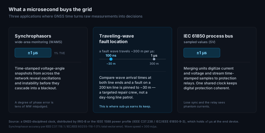
Three applications turn raw substation measurements into grid-level decisions, and each one is only as good as its clock.
Synchrophasors — phasor measurement units, or PMUs — time-stamp voltage and current phasors across the whole network so operators can see the grid as one coherent picture. Line up those angles from hundreds of kilometres apart and you can watch an inter-area oscillation grow, or spot the stress that precedes a cascade, in time to act. A degree of phase error is tens of megawatts misjudged, which is why the timing has to be tight.
Traveling-wave fault location is where sub-microsecond time pays for itself outright. A fault launches a transient that races down the line at roughly 300 metres per microsecond — near the speed of light. Compare the wave’s arrival time at each end of the line and the fault position falls straight out of the difference. At 1 µs of timing error that is ~300 m of uncertainty; modern locators time to around 100 ns and pin a fault on a 200 km line to about 30 m. That is the difference between dispatching a crew to a coordinate and walking the line for a day.
The IEC 61850 process bus carries the digital substation. Merging units digitize current and voltage and stream time-stamped sampled values to protection relays over Ethernet. Every device has to share one clock, or a relay reconstructs phantom currents from samples that don’t line up — so the process bus needs the same microsecond-class discipline.
The standard: ±1 µs and the power profile
The synchrophasor accuracy standard, IEEE C37.118.1 (now folded into IEC/IEEE 60255-118-1), is written as a 1% Total Vector Error — the difference between the measured phasor and the truth, as complex numbers. In pure time terms 1% TVE is a loose bound, around 26 µs at 60 Hz, but that budget has to absorb every other error too, so practical guidance calls for time synchronization far tighter: as PAC World summarizes, PMUs want a source good to within a few microseconds and preferably better than half a microsecond.
The industry settled that into a concrete number. The IEEE 1588 (PTP) power profiles — the original IEEE C37.238-2011, since split into the base profile IEC/IEEE 61850-9-3:2016 and the extended IEEE C37.238-2017 — all guarantee ±1 µs at the end device. That is the figure to design to: a substation clock that delivers ±1 µs to every relay and PMU covers synchrophasors, sampled values, and fault location at once.
| Application | Time requirement | Standard |
|---|---|---|
| Synchrophasors (PMU) | 1% TVE; ±1 µs sync target | IEEE C37.118.1 / IEC/IEEE 60255-118-1 |
| Process bus / sampled values | ±1 µs | IEC 61850-9-2, IEC/IEEE 61850-9-3 |
| Traveling-wave fault location | ~100 ns for ~30 m | (timing-limited) |
| PTP distribution to devices | ±1 µs at end device | IEEE C37.238 / IEC/IEEE 61850-9-3 |
How grid time is delivered
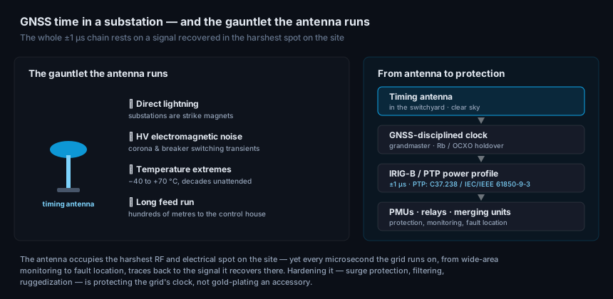
The source is a GNSS-disciplined clock at the substation — a grandmaster that recovers UTC from the satellites and holds it in a rubidium or oven-controlled oscillator. From there the time reaches the equipment two ways: the legacy path is IRIG-B, a coded timecode over dedicated wiring, still ubiquitous in existing yards; the modern path is PTP running the power profile over the station Ethernet, which carries ±1 µs and scales to the process bus. Many substations run both during the long migration from copper timecode to packet timing.
GNSS is the reference the whole scheme is traceable to because it is, as the utility literature puts it plainly, the most available and economical source of precise time on the planet. But “available” assumes the receiver can see the sky cleanly — and that assumption is the antenna’s job to keep.
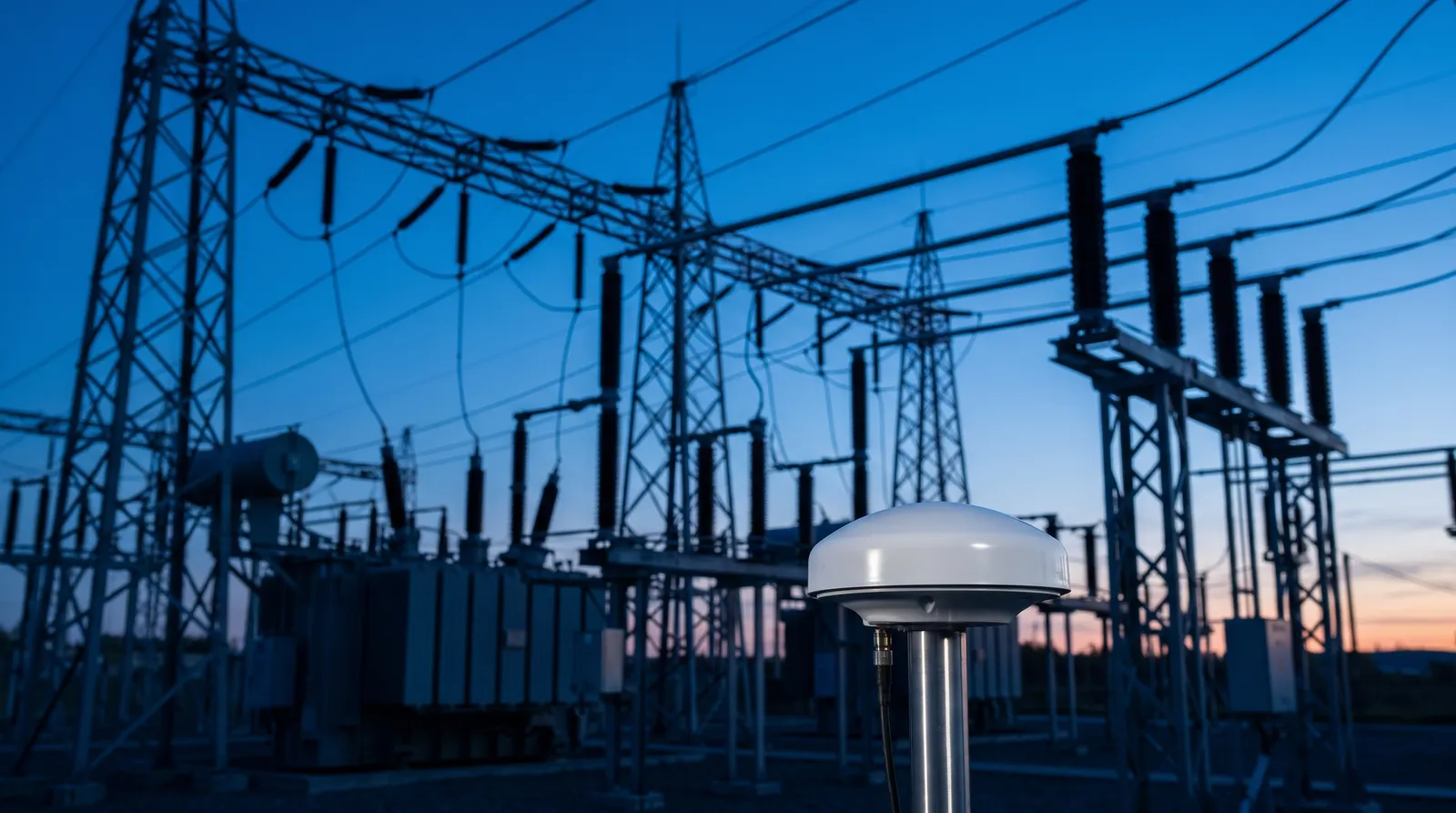
The substation is brutal on antennas
Every microsecond above depends on a signal recovered at a component sitting in the electrically nastiest place a GNSS antenna can be asked to work. A substation antenna faces, all at once:
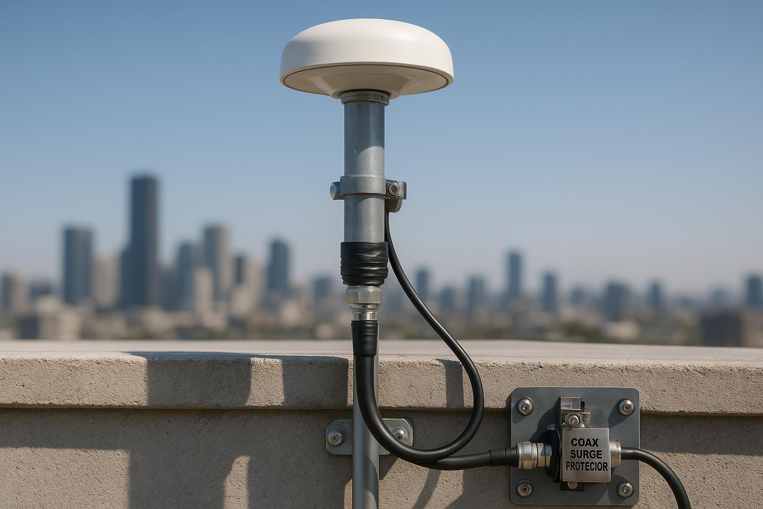
- Direct lightning. Substations are strike magnets — tall steel in open ground — and the antenna is often the highest, most exposed point. Surge protection and proper bonding aren’t optional here; they are what stands between a storm and a dead timing system. It is worth treating as its own design problem, covered in the note on 1 kV lightning protection.
- High-voltage electromagnetic noise. Corona discharge and the broadband transients of breakers switching hundreds of kilovolts sit metres from the antenna. Without strong out-of-band rejection and pre-LNA filtering, that energy raises the noise floor and erodes the carrier-to-noise ratio the receiver needs to hold lock.
- Temperature and time. −40 to +70 °C swings, UV, and decades of unattended service in an outdoor yard are the baseline, not the exception.
- Long feed runs. The antenna is out in the yard or on the roof; the clock is in the control house, often hundreds of metres of coax away. That run has to be budgeted for loss and its fixed delay calibrated out.
So specifying a substation timing antenna is a reliability decision. The traits that matter map onto exactly these threats — the same set a timing-grade antenna is built around:
| Spec | Why it matters in a substation |
|---|---|
| Multi-band, multi-constellation | a steadier, more available reference and resilience if one system is degraded |
| Strong multipath rejection | metal structures everywhere turn reflections into timing error |
| Out-of-band rejection, pre-LNA filtering | survives corona and switching noise without desense |
| Integrated surge protection | the antenna is a lightning entry point into the control house |
| High LNA gain for long feeds | closes the link budget over a long yard-to-control-house run |
| Wide temperature range, IP-rated, UV-stable | outdoor exposure for the life of the substation |
The hardware detail — mounting, grounding, cable loss budgeting — is worked through in the rooftop timing antenna installation guide and the ultimate specifier’s guide.
When the sky goes dark: jamming, spoofing, and holdover
Grid time is critical-infrastructure time, which makes it a target. GNSS jamming and spoofing are no longer theoretical for utilities, and a spoofed clock is worse than a lost one — it fails silently, feeding plausible but wrong time into protection and monitoring. The clock’s answer is holdover: when GNSS drops, the rubidium or OCXO oscillator carries time within budget for a while, buying hours to restore the reference.
But holdover is the backstop, not the plan. The antenna’s real contribution to resilience is keeping GNSS locked so holdover is rarely needed — reliable multi-constellation tracking so no single constellation’s outage matters, and enough interference and multipath rejection to hold C/N0 through corona, switching noise, and low-level interference. Squeezing margin out of a difficult site is its own discipline, covered in improving GNSS antenna SNR and holdover.
The same clock-and-antenna pattern shows up across critical timing — 5G networks hold ±1.5 µs across cells, and data centers and financial venues prove traceability to UTC. The grid’s version is simply the one with the harshest antenna environment and the highest cost of getting it wrong.
Frequently asked questions
What time accuracy does a power grid need? The working standard is ±1 µs at the end device, guaranteed by the IEEE 1588 power profiles (IEEE C37.238 / IEC/IEEE 61850-9-3). Synchrophasors are specified as 1% Total Vector Error under IEEE C37.118.1 / IEC/IEEE 60255-118-1, and IEC 61850 process-bus sampled values also need ±1 µs. Traveling-wave fault location benefits from tighter still — around 100 ns.
Why does traveling-wave fault location need such precise time? A fault wave travels down the line at roughly 300 m per microsecond, and the fault position comes from comparing its arrival time at each end. Every microsecond of timing error is about 300 m of location uncertainty, so locators that time to ~100 ns can pin a fault on a long transmission line to about 30 m — a targeted crew dispatch instead of a line patrol.
IRIG-B or PTP for substation timing? IRIG-B, a coded timecode over dedicated wiring, is the long-established method and still fills most existing yards. PTP running the IEC/IEEE 61850-9-3 power profile over station Ethernet is the modern path — it carries ±1 µs and scales to the digital process bus. Many substations run both during migration.
Does GNSS jamming threaten the grid, and what protects against it? Yes — utilities treat GNSS jamming and spoofing as real risks. The clock rides through short outages on rubidium or OCXO holdover, but the durable defence is an antenna that keeps GNSS locked in the first place: multi-constellation tracking and strong interference and multipath rejection so holdover is rarely called on.
Why is the substation so hard on a GNSS antenna? It combines direct lightning exposure, high-voltage electromagnetic noise from corona and breaker switching, wide temperature extremes, and long cable runs — all at once, for decades. A substation timing antenna needs surge protection, strong out-of-band filtering, multipath rejection, and full ruggedization to hold a clean, traceable signal in that environment.
Written by GNSource Engineering. GNSource manufactures GNSS timing and synchronization antennas for utility, telecom, and data-center infrastructure. Talk to our engineers about a substation-hardened timing antenna, or explore the timing & synchronization line.