I’ve commissioned timing sources on rooftops that share space with C‑band panels, HVAC decks, and the occasional flock of pigeons. One pattern keeps repeating: the site meets lab specs but drifts in the field because the antenna choice and placement weren’t treated as part of the timing chain. Here’s the deal—your packet sync plan can be perfect, your GNSSDO rock‑solid, but if the front end is taking multipath or getting nudged by out‑of‑band energy, the 1PPS time error (TE) histogram will spread and your phase alignment budget will vanish.
For 5G NR TDD, practical guidance holds system phase alignment tighter than about 3 µs across cells, often budgeted as ±1.5 µs to a common reference. Ericsson summarizes this target and typical solutions in its engineering overview, and the ITU‑T G.827x framework details how the end‑service, network, and equipment budgets stack up. See the engineering summary in the Ericsson Technology Review and the application accuracy classes in ITU‑T G.8271 for context: according to the engineering article on synchronization requirements, “cell phase synchronization must be better than 3 µs,” and G.8271 frames ±1.5 µs as the end‑application target for class‑4 use cases (Ericsson Technology Review; ITU‑T G.8271).
Think of GNSS timing antennas as the first gain stage of truth. If they skew group delay, wander in phase‑center behavior, or admit multipath, the receiver’s measurements shift and your TE grows. The good news: a careful spec, clean mount, and disciplined RF budget can bring a marginal site comfortably inside the envelope.
Everything in the GNSS timing antenna library
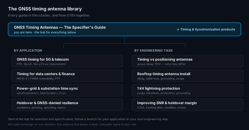
This guide is the hub. Below it sits the full library — pick the branch for your application or your next engineering task, and each article links back here.
By application
- GNSS timing for 5G & telecom — PTP, SyncE, and the ±1.5 µs requirement
- Timing antennas for data centers & finance — MiFID II / FINRA traceability and PTP
- Power-grid & substation time synchronization — synchrophasors, fault location, and the ±1 µs standard
- Holdover & GNSS-denied timing resilience — oscillators, jamming, spoofing, and layered defense
By engineering task
- Timing vs positioning antennas — group delay, PCV, and why the two differ
- How to install a rooftop timing antenna — siting, cable-loss budget, grounding, and surge entry
- 1 kV lightning protection for GNSS — surge standards, protector specs, and grounding
- Improving GNSS antenna SNR & holdover — C/N0, tracking jitter, and oscillator choice
When you’re ready to spec hardware, the timing & synchronization antenna line is built for exactly these duties.
The antenna parameters that actually move your time error (GNSS timing antennas)
Several specifications consistently show up in field fixes. Here’s what matters and why.
Parameter | Why it moves time error | What I demand in practice |
|---|---|---|
Group delay (GD) flatness/stability | Ripple or thermal drift in GD maps directly into 1PPS bias and jitter (ns in, ns out). | Vendor publishes mean GD and ripple across each band; evidence of thermal stability. |
Phase Center Offset/Variation (PCO/PCV) | Millimeter‑level path change = picosecond‑level time change; varying with elevation/azimuth corrupts timing. | Documented PCO/PCV files; absolute calibration preferred; tight PCV with elevation. See fundamentals in Navipedia’s Antenna Phase Centre. |
Axial ratio (RHCP purity) | Poor RHCP purity lets LHCP multipath bleed in, distorting code/phase. | Low axial ratio across passbands, including low elevations. |
Low‑elevation pattern | Too much low‑elevation gain increases multipath; too little hurts continuity. | Controlled roll‑off with symmetry; published pattern plots. |
Out‑of‑band (OOB) rejection | Nearby LTE/5G transmitters can overload early stages and desensitize GNSS. | SAW/BAW/ceramic pre‑filtering with rejection near local bands; overload specs. |
Active LNA gain/noise figure | Under‑gained: SNR loss; over‑gained: overload and intermod. | Gain sized to beat cable/connector loss by ~3–10 dB, with headroom. |
Two quick conversions I keep handy on rooftops: 1 mm of path change ≈ 3.336 ps of time; 1 ns ≈ 0.3 m. Small mechanical or electrical shifts can be visible in TE once the rest of your chain is quiet.
Why this matters for UAV RTK, private 5G, and edge sites
If your fixed site hosts RTK corrections for a drone fleet, antenna‑induced biases don’t just nudge a lab plot—they perturb base‑rover ambiguity resolution and expand outage tails. I’ve watched a base station beside a reflective parapet produce a noisier MP observable and intermittent AR resets downlink, which then cascaded into longer convergence for the rovers. On the 5G side, a noisier 1PPS at the GNSSDO forces the downstream PTP chain to burn more of its budget in cleaning up cTE/dTE. You won’t see catastrophic failures every day; what you’ll notice is increased p‑p spread in TE histograms during certain azimuth sweeps, subtle SNR dents near the C‑band panel heading, and a rise in sync alarms when it rains. Fixing the antenna, mount, and RF budget usually removes the burr under the saddle.
Common engineering mistakes I still see on rooftops
-
Mounting the antenna within a few meters of a C‑band 5G panel or next to metal parapets and HVAC rails, then blaming the receiver when C/N0 dips and TE p‑p breathes with azimuth.
-
Sizing LNA gain to a spreadsheet without considering local RF power—ending up with a marginal SNR (under‑gain) or an overloaded front end (over‑gain) when the panel next door lights up.
-
Assuming “dome equals low multipath” without checking pattern symmetry, axial ratio at low elevation, or asking for PCO/PCV files.
-
Running long RG‑series coax “because it was on the truck,” losing several dB and pushing the noise figure up; skipping the surge arrestor or bonding it with a long, coiled strap.
-
Commissioning with “it locks and holds” rather than recording a C/N0 baseline, a 1PPS TE histogram, and a short holdover test for future health checks.
Selection and procurement: what to ask for and why
You can avoid most back‑and‑forth by demanding specific, timing‑relevant artifacts up front. Use this compact matrix when you talk to vendors.
Spec/Artifact | Why you need it | Target/Ask |
|---|---|---|
PCO/PCV files (absolute if available) | Quantify elevation/azimuth‑dependent delay; feed into your calibration. | Small, smooth PCV; documented temperature stability. |
Group delay vs. frequency | Directly affects TE bias/jitter; ripple shows multipath susceptibility or filter issues. | Flat within the passband; ns‑level ripple budgeted. |
Axial ratio across band and elevation | Ensures RHCP purity and multipath rejection. | Low AR (ideally <3 dB typical) even at low elevations. |
Pattern plots (gain, symmetry, back‑lobes) | Predicts low‑elevation behavior and LHCP suppression. | Symmetric, controlled roll‑off; low back‑lobes. |
OOB rejection and overload specs | Survives co‑sited LTE/5G carriers without desense. | Pre‑filters (SAW/BAW/ceramic) with published rejection near local bands; IIP3/1 dB compression data. |
Environmental and surge | Keeps uptime in real weather and transients. | IP67+, UV stable, documented lightning/surge path. |
Integration notes | Smooth mechanical/electrical install. | Connector type, recommended cable runs, power range. |
Ask for sample calibration files and a short app note showing how the antenna’s GD/PCV were measured. If a timing antenna is serious, the files exist.
Installation, cabling, grounding, and surge protection
Mounting and cabling are not clerical tasks—they are performance levers. A few field‑tested guidelines:
-
Siting and mounts. Prioritize a clear 360° view and keep a healthy offset from reflective structures and active RF panels. Rigid, plumb masts matter; if the mount flexes, the cable moves and so does your TE. UNAVCO’s practical notes on rooftop monuments and siting remain an excellent primer on what “rigid and clear” really means in the field (UNAVCO GNSS antenna mounts).
-
Coax and loss budgeting. For 50‑ohm runs, LMR‑400 and LMR‑600 are the common workhorses. At L1, LMR‑400 is roughly 5.3 dB/100 ft, while LMR‑600 is about 3.5 dB/100 ft per the manufacturer’s datasheets (Times Microwave LMR‑400; LMR‑600 values are similar family data). Add ~0.5–1 dB for connectors and arrestors, depending on parts.
Worked example: Suppose a 100‑ft LMR‑400 run at L1. Cable ≈ 5.3 dB + connectors/arrestor ≈ 0.7 dB → ~6 dB total. Size the active antenna/LNA for ~15–20 dB so you beat loss by ~9–14 dB, leaving headroom for temperature swings and frequency diversity. On a noisy rooftop, I’ll bias toward the lower end of gain and add pre‑filtering to avoid overload rather than jamming more gain into the first stage.
-
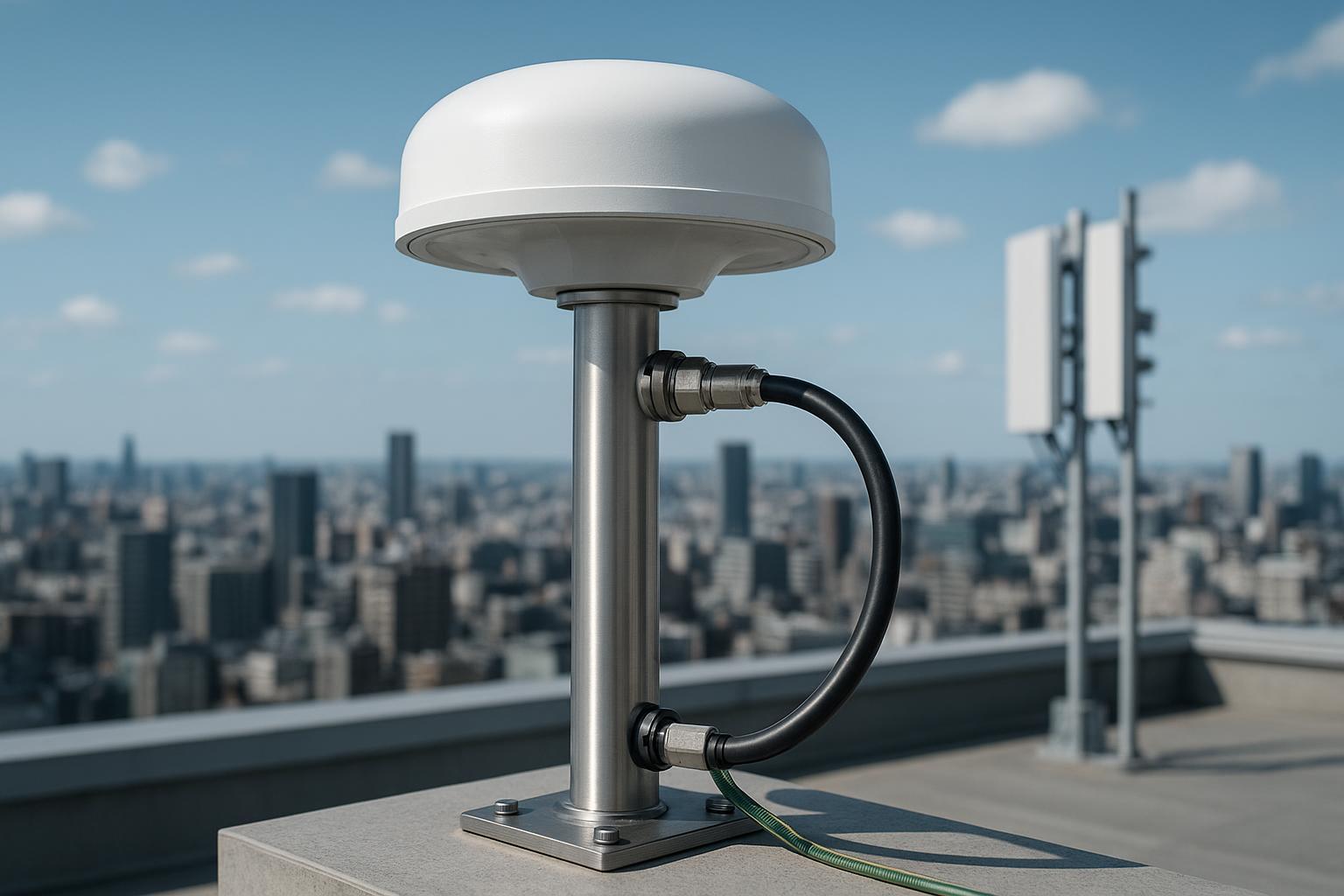
Grounding and surge. Place the arrestor at building entry and bond the mast, arrestor, and coax shield to the building’s grounding electrode system with short, straight conductors. Weatherproof connectors with proper tape and boots; re‑inspect annually. I’ve traced intermittent TE outliers to a single cracked boot that wicked water into a connector, changing impedance just enough to dent C/N0.
Validation and commissioning that won’t be second‑guessed later
Commissioning is where you create a baseline and catch site‑specific issues while the lift is still rented.
-
C/N0 baseline. Log per‑satellite C/N0 for a full sky sweep (several hours). Store the baseline; it becomes your canary during future alarms. Practical quick‑reference procedures for 5G sync tools are outlined in the OneAdvisor guide by VIAVI, which also shows how to view GNSS performance in context of time sync workflows (VIAVI 5G sync and timing quick reference).
-
1PPS TE histogram. Measure TE against a trusted reference and record the histogram once the site is surveyed and locked. Note mean offset, RMS/jitter, and p‑p. For telecom‑grade sources under clean sky, tens of nanoseconds of spread are routine; degraded sites can push toward hundreds. Tooling varies—handhelds, receivers with built‑in stats, or lab gear—but the goal is the same: a repeatable acceptance trace.
-
Holdover check. Interrupt GNSS and watch the oscillator’s error growth and reacquisition behavior. Document against the receiver/oscillator spec. This simple test has saved me midnight truck rolls when a lightning event took out rooftop power but the core kept time within plan.
Store these three artifacts with photos of the install and a sketch of nearby RF emitters. When someone asks “what changed?” you’ll have more than a memory.
Interference and resilience options for hostile RF sites
Urban rooftops are not anechoic chambers. Co‑sited LTE/5G transmitters, repeaters, and even rooftop Wi‑Fi can stress a GNSS front end.
-
Filtering before gain. Prefer antennas or masthead modules with SAW/BAW/ceramic pre‑filters that notch nearby bands so the LNA isn’t forced to operate in the shadow of a strong blocker.
-
Low‑multipath form factors. Choke‑ring and carefully designed low‑multipath domes suppress reflections at the antenna aperture. A recent DLR‑indexed 2025 paper cataloged geodetic‑grade choke‑ring performance, reaffirming their place when stability trumps everything else (DLR listing for a 2025 choke‑ring study).
-
CRPA and null‑steering. When intentional interference or persistent urban noise is in play, controlled‑reception arrays can spatially filter interferers. GNSource’s anti-jamming CRPA antennas can augment site resilience when paired with receivers that expose interference metrics and beamforming controls. Keep expectations grounded: CRPA adds cost and integration complexity; use it where the risk profile justifies it.
-
Design for resilience beyond RF. Government and expert guidance frames resilience as Protect, Toughen, Augment, and Operate—use filtering and good siting (Protect), multi‑constellation and holdover (Toughen), diverse references like PRTC/ePRTC/PTP/fiber (Augment), and planned incident response (Operate). A concise overview appears in recent advisory materials on GNSS resilience (GPS.gov/CISA PTA overview).
Engineering scenario: moving a “good enough” timing site into spec
This scenario mirrors a composite of real deployments; numbers are realistic ranges, not lab‑grade claims.
-
Baseline site. Low‑multipath dome on a short mast, ~6 m from a C‑band 5G panel, 80 m of LMR‑400, active antenna with ~20 dB gain and minimal pre‑filtering. Symptoms: C/N0 dents by ~2–4 dB‑Hz in azimuth sectors near the panel; MP observable shows periodic elevation‑dependent ripples; 1PPS TE histogram p‑p ~120–180 ns on windy afternoons, tighter overnight.
-
Mitigation plan. Move the antenna to a clearer corner, +2 m mast height but >12 m lateral from panels; upgrade to a choke‑ring or a dome with documented low PCV and strong axial ratio at low elevations; swap to 80 m LMR‑600 (cutting loss by ~1.8 dB vs LMR‑400 at L1); add a pre‑filter stage ahead of high gain; re‑terminate with a proper arrestor at entry and short bonding.
-
Observed result. Baseline C/N0 improves by ~2–3 dB‑Hz across most of the sky; MP amplitude visibly drops; TE histogram tightens to ~40–70 ns p‑p in daytime traffic with mean offset stable across diurnal temperature shifts. The PTP chain upstream reports fewer wander excursions. None of this required a new receiver—just the right antenna class, a better mount, a saner RF budget, and clean bonding.
If your site is more hostile (airport radars, public‑safety towers), taper expectations and consider CRPA or fiber‑delivered time.
Key takeaways
-
A timing plan that ignores the antenna is a budget with a hole. Group delay behavior, PCO/PCV, axial ratio, and OOB rejection directly shape 1PPS TE.
-
Size LNA gain to beat coax loss by ~3–10 dB, not to a round number. Use LMR‑600 or better for long runs; place the first low‑noise gain as early as possible.
-
Mount for physics, not convenience: distance from panels and reflectors matters as much as sky view. Bond short and straight; weatherproof everything.
-
Commission like you’ll be audited: C/N0 baseline, 1PPS TE histogram, holdover check, photos, and notes on nearby emitters.
-
For hostile rooftops, combine filtering and low‑multipath geometries; escalate to CRPA when the risk and budget agree.
FAQ
Do I need a choke‑ring for every telecom rooftop?
No. Choke‑rings shine when multipath is stubborn and stability trumps cost and size. Many clean sites do fine with a well‑designed low‑multipath dome that has documented PCV/PCO and good axial ratio. Use the siting constraints and your TE histogram to decide.
How many times should I mention “GNSS timing antennas” in my spec or report?
Once in the title and once in a section header is enough for clarity. In technical text, focus on the parameters (GD, PCO/PCV, AR, OOB rejection) rather than repeating the phrase. For search discoverability, include the term naturally a handful of times—quality over repetition.
What’s an acceptable TE histogram for commissioning?
Context matters, but tens of nanoseconds p‑p under good sky are routine for telecom‑grade sources once surveyed and locked. If you’re consistently north of ~100 ns p‑p with clear sky, re‑check siting, coax, bonding, and filters before blaming the receiver.
Can I fix a noisy site with more LNA gain?
Usually not. Extra gain can mask a poor noise figure or, worse, drive overload in the presence of strong out‑of‑band signals. Fix siting, loss, and filtering first, then right‑size gain.
Where in the network should I place holdover capability?
At every point where losing GNSS would impact service. The rooftop source needs a disciplined oscillator; so do key distribution nodes. Treat holdover as part of timing hygiene, not an optional extra.
If your deployment is safety‑critical, involve certified integrators and demand vendor review of your antenna calibration and RF budget. And if you’re choosing between otherwise comparable GNSS timing antennas, pick the vendor that can hand you clean PCV/PCO and group‑delay plots without a scavenger hunt.