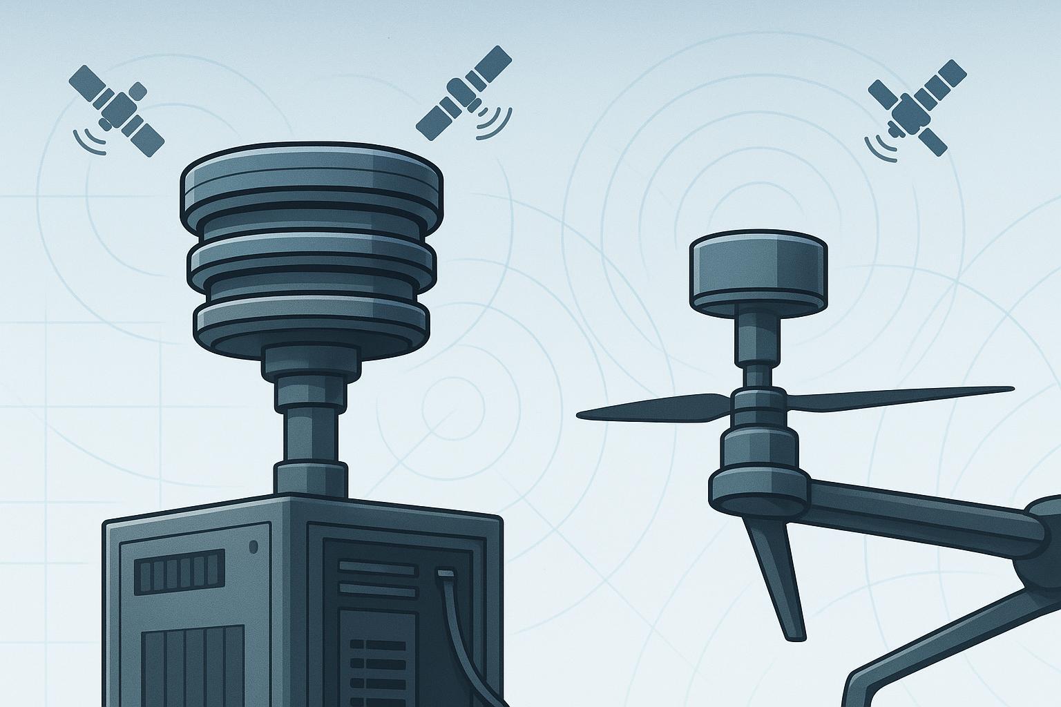
If your RTK drone holds centimeter accuracy everywhere except near the depot—right when the video transmitter spins up—you’re not alone. On the roof, a bulky timing-grade antenna feeds a rock‑solid PTP/GNSSDO. On the airframe, a compact helix or patch fights motion, multipath, and interference. Both are “GNSS antennas,” but they’re optimized for different jobs and tested in very different ways.
Below, I’ll lay out the practical differences I’ve seen in lab and field tests—what to measure, how to install, and when to pick timing‑grade hardware versus a lightweight positioning antenna for RTK UAVs. For a deeper treatment of specifying the timing‑grade side, see our ultimate specifier’s guide to GNSS timing antennas.
TL;DR: When to choose each (and how to test)
-
For fixed depot timing, microcell/backhaul, or survey bases that must hold phase and time: pick a timing‑grade antenna with documented group delay stability (GD/GDV), low phase‑center variation (PCV), and strong multipath suppression; validate with group‑delay sweeps, PCV calibration, and timing KPIs (TDEV/MTIE).
-
For UAV rovers under motion: pick a compact, low‑axial‑ratio, multi‑band positioning antenna that maintains clean RHCP across elevation angles; validate with dynamic RTK flight tests (fix ratio, CN0 stability, reacquisition) and interference checks near your own radios.
-
There’s no single winner. Use a timing‑grade antenna on the ground where weight doesn’t hurt you, and a calibrated lightweight antenna on the airframe where orientation, AR, and integration dominate.
Key concepts engineers actually measure
Group delay and GDV
- The slope of phase through the antenna and front‑end. Timing nodes care about absolute stability across frequency, angle, and temperature because delay wander feeds directly into time error. Positioning rovers care more about consistency, especially inter‑band differentials that affect ambiguity resolution. Practical method: VNA-based S21 phase‑slope, plus angle sweeps and thermal runs. For a compact lab overview of group-delay testing, see the concise lab methods in the Rohde & Schwarz GNSS testing pocket guide (accessed 2026).
Phase center offset/variation (PCO/PCV)
- The effective electrical phase origin and how it moves with azimuth/elevation and frequency. Centimeter workflows need low, well‑characterized PCV with the right calibration file applied in processing. Absolute calibration (NGS/IGS style) is preferred. Background and calibration resources are maintained by the U.S. National Geodetic Survey at NGS Antenna Calibration (ANTCAL).
Axial ratio (AR)
- A measure of circular polarization purity. Lower AR (e.g., ≤2 dB near zenith; ≤3–4 dB at 20° elevation is a solid target) rejects cross‑polarized multipath and improves RTK fix robustness under motion. Practical integration targets and placement tips are summarized in ESA Navipedia’s GNSS Antennas reference.
Multipath suppression
- Choke‑ring geometry, ground‑plane size, and pattern shaping reduce low‑elevation reflections. It’s essential on rooftops and still meaningful for UAVs during takeoff/landing and operations near buildings.
Radiation pattern coverage
- For UAVs, you want a uniform sky dome with acceptable low‑elevation gain because the vehicle will roll, pitch, and yaw. For timing, you want continuous low‑elevation coverage without deep nulls.
Out‑of‑band rejection and interference robustness
- Pre‑filters and LNA linearity keep LTE/5G, telemetry, and video Tx from collapsing CN0 or inducing cycle slips. On a UAV, spatial separation and cable routing matter as much as filter curves. At the receiver/chain level, the ETSI framework EN 303 413 describes blocking/out‑of‑band immunity expectations in the L1/E1 and L5/E5 ranges.
GNSS timing vs positioning antenna: design and testing compared
Two classes, same satellites, very different priorities. Here’s how I brief teams before procurement.
Dimension | Timing‑grade Antenna (fixed node) | Positioning‑grade Antenna (UAV rover) |
|---|---|---|
Best for | Depot timing nodes, PTP/GNSSDO anchors, survey bases | RTK/PPK UAVs, autonomous robots, mobile mapping |
Primary design goal | Ultra‑stable group delay and minimal PCV; strong multipath rejection | Broad, uniform sky coverage with low axial ratio; compact and light |
Bands | Often multi‑band (L1/L2/L5/E6) with controlled inter‑band delay | Dual/triple‑band common for fast integer fixing |
Group delay stability | Characterized in ps/ns across temp/angle; tight inter‑band differentials | Consistent enough for RTK; focus on differential delay and repeatability |
PCO/PCV | Documented via absolute calibration; per‑band PCV models expected | Prefer documented PCV; lighter units may have higher PCV—compensate in processing |
Axial ratio | Good, but not the top design constraint | Critical: maintain low AR across elevation to hold fixes under motion |
Multipath suppression | Choke‑ring/ground‑plane heavy; excellent low‑elevation control | Geometry‑driven; relies on placement/stand‑off more than mass |
Pattern coverage | Emphasis on low‑elevation continuity and stability | Emphasis on full dome with minimal nulls under attitude changes |
OOB rejection | Strong pre‑filters; rooftop RF immunity focus | Pre‑filters plus spatial separation from onboard Tx |
Size/weight | Large/heavy; irrelevant on rooftops | Small/light; directly affects endurance and CG |
Temperature stability | Characterized; low ps/°C targets | Must not drift enough to hurt RTK consistency; verify in chamber if operating wide temps |
Testing focus | GD/GDV vs band/angle/temp; PCV calibration; TDEV/MTIE | AR and pattern sweeps; dynamic RTK fix rate, CN0 histograms; interference A/B |
Note: Specific values vary by model. Always verify with current datasheets and your own validation. This section explicitly targets the query “GNSS timing vs positioning antenna” to support search intent for engineers comparing classes.
Why this difference matters for RTK UAV reliability
In flight, attitude changes modulate what the antenna “sees.” A compact unit with low axial ratio across the sky maintains clean RHCP even when the airframe yaws into a reflective façade. That translates into steadier CN0 and fewer cycle slips, which keeps your integer fixes locked. On the ground, a timing node doesn’t move—but low‑elevation multipath and temperature drift will quietly bias time unless group delay and PCV are tightly controlled and documented.
When we’ve swapped between comparable multi‑band UAV antennas, the best predictor of on‑air fix stability wasn’t a single gain number—it was the combination of axial ratio at low elevation, pattern uniformity, and how the antenna behaved when mounted near carbon fiber. Think of AR as the “purity filter,” pattern as the “coverage map,” and installation as the “final boss.”
If you’re comparing UAV options, also review vendor integration notes on axial ratio targets and placement; they outline practical thresholds engineers use in production builds, as discussed in the 2024 Taoglas guide. For onboarding a depot timing node, receiver manuals highlight strict group‑delay and inter‑signal budgets—the antenna and its active front‑end must meet them to keep time wander low at the system level. A representative example is u‑blox’s multi‑band precision integration guidance in 2024–2025.
For UAV readers evaluating compact antennas and airframe constraints, see GNSource’s Aviation & UAV GNSS Antennas | Lightweight PNT overview.
References for claims in this section:
-
Axial ratio and integration targets summarized by ESA Navipedia: GNSS Antennas.
-
Receiver‑level integration constraints and multi‑band considerations: u‑blox ZED‑F20P Integration Manual (2024‑07‑25).
A realistic engineering scenario: flight A/B that actually isolates the antenna
Goal
- Compare a lightweight helix against a low‑profile patch for an RTK UAV rover without confounding variables.
Method I trust in the field
-
Two matched airframes, same firmware and RTK stack, same receiver model, same camera payload. Mount antennas at equal heights; keep coax lengths identical. Fly the same figure‑eight and ladder patterns at three altitudes. Include a pass along the depot edge where telemetry and video Tx are active.
-
Log raw observations (RINEX/UBX), CN0 per satellite, fix state over time, cycle slip events, and PPK/RTK solutions versus surveyed GCPs. Trigger two short self‑occlusions (brief roll/pitch maneuvers) to test reacquisition.
What you’ll typically observe
- The helix with lower AR across elevation tends to hold higher median CN0 at low elevation and shows fewer slip bursts when the fuselage or boom partially masks the sky. The low‑profile patch can match results in clean RF but is more sensitive to carbon‑fiber proximity and ground‑plane adequacy. Reacquisition time correlates with how cleanly the antenna preserves polarization during attitude changes.
How to present it for sign‑off
- CN0 histograms split by elevation band, fix‑ratio over mission time, and RMS horizontal/vertical error against GCPs. If you can, replicate with a lab blocker injecting LTE or 2.4/5.8 GHz to quantify margins. For laboratory context and procedures, see the concise overview in Rohde & Schwarz’s GNSS testing pocket guide (accessed 2026).
Common engineering mistakes that cause avoidable regressions
I keep seeing teams evaluate antennas with the receiver’s defaults and a bench coax, then declare a winner before flight. That misses installation sensitivity—the dominant source of surprises. Mounting a patch directly on carbon fiber without the specified ground plane, routing GNSS coax parallel to a 2.4/5.8 GHz loom, or placing the antenna below a vibrating mast are classic ways to degrade AR and pattern. For timing nodes, skipping PCV calibration or ignoring temperature‑dependent group delay drift can add quiet bias that only shows up as time wander in TDEV days later. Finally, mixing antenna radome or cable types between calibration and production units breaks the very corrections you thought you had.
Practical improvement checklist (from lab to flight)
-
Validate the right metrics: for timing, measure GD/GDV vs band/angle/temp and obtain PCV files; for UAVs, sweep AR and pattern, then prove it with dynamic RTK flight logs.
-
Mount correctly: honor ground‑plane requirements, add a non‑conductive standoff above carbon fiber, and keep a clear sky dome.
-
Control interference: maximize separation from telemetry/video/LTE radios; cross at 90° if you must intersect cable runs; add pre‑filters if CN0 dips near your own transmitters. In RF‑dense depots, consider spatial diversity or anti‑jam arrays when appropriate; for a neutral reference on array options, see Anti‑Jamming CRPA Antennas — 4 to 32 Elements.
-
Temperature and environment: chamber‑test representative samples; record ps/°C delay coefficients for timing nodes and spot‑check UAV antennas for pattern/AR drift.
-
Processing discipline: use the exact antenna/radome model in your software, apply PCV/PCO correctly, and keep cable/radome types consistent between calibration and production.
Pricing and version scope (as of 2026‑05‑22)
Expect wide variance. Timing‑grade choke‑ring/geodetic antennas typically range from roughly USD 1,500–5,000+ depending on band count and calibration options; compact UAV helix/patch units run roughly USD 20–300 (premium multi‑band up to ~USD 500). These figures are indicative and subject to change; certified aviation/defense variants and regional supply add premiums. For context on why timing antennas warrant the spend in assured PNT applications, see NovAtel’s overview of timing’s role in resilient PNT (2026).
Version volatility notes
- Antenna LNAs/filters, supported bands, and firmware features in “smart” antennas change fast. Always verify the latest datasheet revisions and, for timing nodes, capture your own group‑delay baselines.
Key takeaways
-
The core split isn’t “better vs worse”; it’s “stable delay and PCV for time” vs “clean RHCP and full‑dome coverage for motion.”
-
For UAVs, low axial ratio across elevation and good integration discipline are what keep RTK fixes glued under attitude changes and RF noise.
-
For timing nodes, treat group delay and PCV like gold—measure them, document them, and monitor TDEV/MTIE over time.
Short FAQ
What is the difference between GNSS timing and positioning antennas?
- Timing antennas prioritize group‑delay stability, low PCV, and multipath suppression for fixed nodes; positioning antennas prioritize low axial ratio, broad sky coverage, and compactness for moving platforms. That’s why their test plans diverge.
Can one antenna serve both roles?
- Sometimes, but compromises creep in. A compact UAV antenna can run a small rooftop base, and a timing‑grade unit can ride on a large UAV, but each is sub‑optimal outside its sweet spot. Use scenario‑fit and your test data to decide.
How do I test group delay properly?
- Derive group delay from VNA phase slope across the passband, de‑embed cables/fixtures, sweep angle in a chamber, and add temperature runs. Compare against a calibrated reference and publish mean, p‑p, RMS, and inter‑band differentials. Receiver‑level timing metrics (TDEV/MTIE) close the loop; for workflow background, see the lab overview in R&S’s GNSS testing pocket guide (accessed 2026).
How important is axial ratio for RTK drones?
- Very. Low AR helps reject cross‑polarized multipath and stabilizes CN0 during motion, which supports integer fixing and reduces cycle slips—especially at low elevation and near reflective structures. For integration targets and examples, refer to the ESA Navipedia reference on GNSS antennas.
What about standards for interference and blocking?
- The ETSI EN 303 413 framework sets blocking/out‑of‑band immunity expectations at the receiver level in the L1/E1 and L5/E5 ranges. Practically, you’ll meet those margins faster with decent antenna pre‑filters and good spatial separation from your own transmitters; see the ETSI Satellite Earth Stations and Systems overview for EN 303 413.
References and further reading
-
ESA Navipedia: GNSS Antennas — practical placement and polarization considerations.
-
u‑blox ZED‑F20P Integration Manual (2024‑07‑25) — multi‑band precision integration guidance.
-
NGS Antenna Calibration (ANTCAL) — absolute PCV/PCO calibration and ANTEX usage.
-
Rohde & Schwarz GNSS testing pocket guide — concise lab methods, including group delay.
-
NovAtel: Why GNSS timing matters in resilient PNT (2026) — system-level rationale for timing stability.