Key concepts without the fluff: C/N0, tracking jitter, and holdover
When engineers say “GNSS antenna SNR,” we’re almost always talking about carrier‑to‑noise density, C/N0 (dB‑Hz). Higher C/N0 tightens both code and carrier loop jitter, cuts the odds of cycle slips, and stabilizes ambiguity resolution. Safran’s concise measurement note explains how C/N0 is defined and why it correlates with ranging stability in practical setups; it’s a useful baseline for interpreting your logs: see the discussion of signal and noise power in the Safran guide Measuring a GNSS Signal and Gaussian Noise Power. According to the same discipline, you should expect healthier tracking, especially at mid‑high elevations, as C/N0 rises. For a vendor perspective on robust tracking and slip mitigation, Septentrio’s overview of robust GNSS signal tracking describes features like LOCK+ aimed at maintaining lock under stress—concepts that all benefit from better C/N0.
-
Reference: Safran’s explanation of C/N0 and measurement context is here: Measuring a GNSS Signal and Gaussian Noise Power (2025).
-
Reference: Septentrio’s robust GNSS signal tracking primer outlines techniques to ride through interference and dynamics (accessed 2026).
Holdover sits downstream of all this. During short GNSS outages (turns, brief masking, or desense), the oscillator carries your timing budget. A higher C/N0 front end reduces slip/reacquire events and shortens those outages; an appropriate oscillator (TCXO or OCXO) limits drift while you’re in holdover. Microchip’s oscillator families overview and Safran timing manuals show why OCXO options provide markedly tighter short‑term stability than TCXOs for the same conditions. The antenna is the other half of that equation—choosing one built for a clean, stable timing front end is the focus of the ultimate specifier’s guide to GNSS timing antennas.
Why better GNSS antenna SNR and UAV GNSS filtering matter in the field
On paper, any modern RTK receiver can fix in open sky. On a drone, the game is different: motors, DC‑DCs, video/telemetry links, and nearby LTE sectors pound the front end. Three outcomes tie directly to GNSS antenna SNR and filtering quality:
-
Fix continuity and re‑fix time. Higher C/N0 reduces cycle slips and shortens re‑fix after maneuvers. Expect visibly steadier fixed RTK when your median L1 C/N0 in unobstructed hover lives in the 40–45 dB‑Hz range and doesn’t crater under throttle or yaw.
-
Timing stability during micro‑outages. Better C/N0 means fewer and shorter outages; pairing that with a disciplined OCXO can keep sub‑microsecond payload sync even when the sky view stutters for a second or two.
-
Integrity under interference. Preselection filtering and adequate LNA linearity preserve headroom so the receiver isn’t desensitized by strong out‑of‑band (OOB) signals.
Practical targets that have held up across platforms:
-
Median L1 C/N0 in clean, unobstructed hover: ≥ 40–45 dB‑Hz (watch the per‑satellite spread; variance matters).
-
Motor‑on penalty: investigate if you see > 2–3 dB‑Hz average drop from motors‑off to hover or sustained throttle.
-
Pre‑LNA loss budget: generally keep ≤ 1–2 dB unless you deliberately trade a bit of NF for stronger preselection to stop blocking.
For ground planes and axial ratio, u‑blox’s application note on GNSS antennas is the most practical single document I point new engineers to—it highlights low axial ratio and adequate ground planes as first‑order effects for phase stability. For timing hardware choices, Microchip’s oscillator overview and Safran timing manuals illustrate why OCXO‑based disciplining is the safer bet when tight holdover matters.
-
Reference: u‑blox GNSS Antennas Application Note (axial ratio, ground plane, filtering trade‑offs).
-
Reference: Microchip oscillators overview (ADEV/stability metrics) and Safran timing manuals (TCXO/OCXO holdover examples).
Common integration mistakes that quietly kill SNR (and how I’ve seen them fixed)
Carbon fiber as a “ground plane.” Carbon is conductive and lossy; place a ceramic patch directly on it and you detune the antenna, warp the RHCP pattern, and amplify multipath. The fix that consistently works: bond a proper circular aluminum plate (≈100–150 mm for L1/L2/L5 patches) and add a short pylon to lift the antenna into a cleaner sky.
Long, lossy coax runs. A 250–300 mm run of micro‑coax snaking past ESCs can burn a dB or more and invite conducted noise. Times Microwave’s datasheets show why picking something like LMR‑195 over thin RG‑174 pays back quickly. Keep the run short, strain‑relieved, and away from power harnesses.
Over‑filtering before the LNA. It’s tempting to throw a sharp filter up front, but every dB before your first low‑noise gain stage raises the cascaded noise figure. Only add as much preselection as needed to stop blocking or desense; when you need cellular rejection, consider antennas/front‑ends with integrated notches designed for GNSS bands.
Ignoring LNA linearity. A “killer” low NF spec isn’t helpful if the front end compresses near a cell sector. In RF‑ugly sites, prioritize LNA linearity (IIP3/P1dB) and OOB rejection over chasing the last 0.2 dB of NF.
Routing next to noise. GNSS coax routed alongside ESC leads, buck converters, or high‑speed digital will show up as repeating C/N0 scalloping in throttle sweeps. Cross at right angles, separate planes, and shield where needed. Power the active antenna from a clean rail and validate current draw against the datasheet.
A realistic A/B scenario: small patch on a carbon deck vs. metal‑backed pylon plus preselect
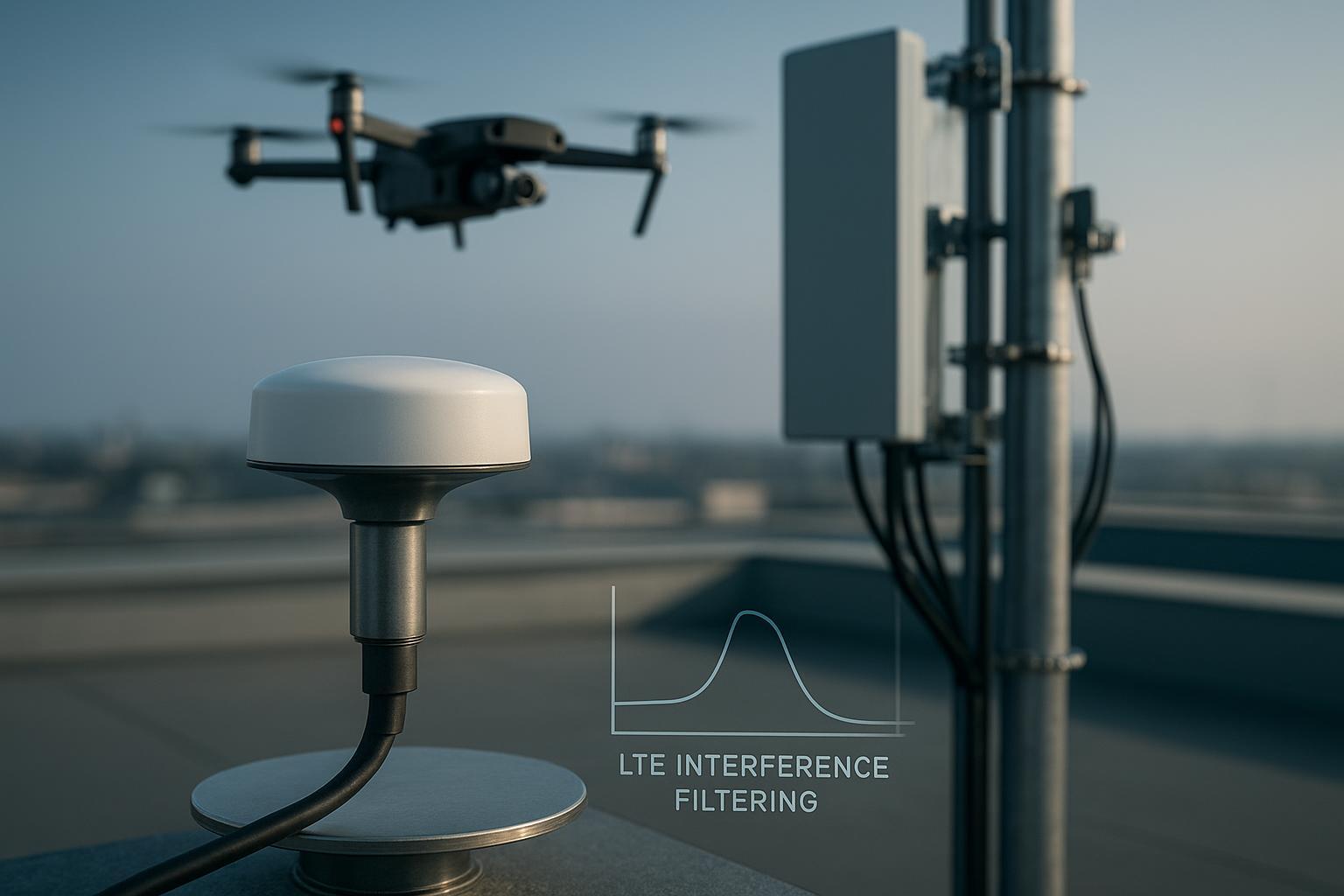
Site and platform. A 4.5 kg multirotor used for inspection flights along a rooftop corridor with a visible LTE sector panel about 120 m away. Original build: dual‑band patch bolted to a small internal metal tab sitting on a carbon‑fiber top deck; ~250 mm of general‑purpose micro‑coax to an RTK receiver near the power distribution board; video transmitter 20 cm aft.
Symptoms (baseline). Motors‑off median L1 C/N0 in the high‑30s dB‑Hz at hover altitude; motors‑on penalty ~4–5 dB‑Hz; frequent single‑satellite collapses when yawing through the sector’s azimuth; elevated cycle slips and occasional fixed‑to‑float transitions.
Interventions (two build days). We:
-
Added a 120 mm circular aluminum ground plane bonded above the carbon deck and mounted the antenna on a 45 mm pylon for a cleaner sky view.
-
Replaced the 250 mm cable with a 120 mm low‑loss coax per manufacturer loss tables and rerouted it away from power and RF.
-
Swapped the antenna to a similar footprint model with stronger OOB rejection; on paper it includes an LTE notch in the L1 path (class similar to u‑blox ANN‑MB3’s concept of built‑in notching as shown in its datasheet).
-
Enabled the receiver’s interference/jamming monitor and logged per‑satellite C/N0 under motors‑off, idle, hover, and repeated yaw sweeps.
Results (same day, same weather). Median L1 C/N0 improved by ~3–5 dB‑Hz (largest gains at 20–40° elevation); motors‑on penalty dropped to ~1.5–2 dB‑Hz; single‑satellite collapses reduced markedly during yaws through the sector; cycle‑slip counts per 10‑minute hover cut by roughly half; fixed RTK held through aggressive heading changes that previously caused re‑fix delays. None of this is magic—just better RF hygiene and a front end that wasn’t being bullied by nearby blockers.
Note on suppliers. A number of vendors offer multi‑band RHCP antennas with good axial ratio and strong OOB rejection suitable for UAVs; for example, GNSS/UAV and RTK‑class models from GNSource are representative of the category. Evaluate any candidate with the tests below before committing to production.
For context on integrated LTE notches in L1‑path antennas, review the u‑blox ANN‑MB3 datasheet; it’s a good illustration of how preselection can be built into an antenna assembly for harsh RF environments.
- Reference: u‑blox ANN‑MB3 datasheet (example of integrated LTE notch approach for GNSS antennas).
Practical improvement checklist (production‑friendly)
-
Antenna and mount: choose a low‑axial‑ratio, multi‑band RHCP antenna; for ceramic patches, provide a symmetric metal ground plane around 100–150 mm; if space is tight, consider a quality helix that isn’t ground‑plane dependent.
-
Placement: top‑mount on a short, rigid pylon with clear sky; keep 10+ cm lateral clearance from high‑current harnesses and VTX antennas where possible; avoid placing directly over carbon without a bonded metal plane.
-
Filtering strategy: start with minimal pre‑LNA loss; add a preselect SAW or an antenna with integrated OOB rejection only when you confirm desense/blocking via logs or quick spectrum checks; when cellular is the offender, prefer a design with a targeted LTE notch.
-
LNA priorities: for RF‑noisy sites, prioritize linearity (IIP3/P1dB) and OOB rejection over squeezing an extra 0.2 dB NF; verify that the first gain stage cannot be pushed into compression by nearby transmitters.
-
Cabling: keep GNSS coax as short as mechanically feasible; select low‑loss cable per manufacturer tables (e.g., LMR‑195 beats RG‑174 in the L1/L2 bands); strain‑relieve and avoid tight bends at connectors.
-
Powering the antenna: provide a clean DC feed within the antenna’s spec; verify current draw vs. datasheet at cold/hot and motor‑on conditions to catch marginal regulators.
-
Firmware: enable interference/jamming monitors and log per‑satellite C/N0; set an elevation mask around 10° to avoid low‑elevation multipath; run multi‑constellation, multi‑band with appropriate priority.
-
Validation (bench/field): record motors‑off/on C/N0 baselines at idle, hover, and sustained throttle; investigate penalties > 2–3 dB‑Hz; perform a ground‑plane A/B test (small tab vs ~120 mm plate); do a proximity blocker test near handheld LTE/telemetry sources with proper safety.
-
Timing path: if payload sync is sensitive, select an OCXO‑based timing option and verify short‑occlusion behavior while logging re‑fix times; the goal is fewer, shorter holdovers and smaller drift during each one.
Helpful references while building your checklist: u‑blox’s antenna application note (ground plane and axial ratio), Times Microwave cable loss tables, and ANN‑MB3’s datasheet for an integrated‑notch example.
-
Reference: u‑blox GNSS Antennas Application Note (axial ratio/ground plane/budgeting).
-
Reference: Times Microwave LMR‑195 datasheet (representative attenuation numbers to budget coax loss).
Key takeaways
-
Higher GNSS antenna SNR (C/N0) is the shortest path to fewer cycle slips, steadier fixes, and shorter re‑fix times; aim for ≥ 40–45 dB‑Hz median L1 in clean hover and keep motor‑on penalties within ~2–3 dB‑Hz.
-
Treat the RF front end as a system: antenna pattern and axial ratio, ground plane, preselection filtering, LNA linearity, cabling, and routing all add—or subtract—decibels you can’t get back in software.
-
Only add as much pre‑LNA filtering as you need to stop blocking; otherwise you’re paying in noise figure. Where cellular is present, an antenna or front end with a targeted LTE notch can make the difference between float and fixed.
-
For platforms with tight timing budgets, better C/N0 reduces the frequency and length of holdovers; pairing that with an OCXO‑based discipline option keeps drift in check during short outages.
Short FAQ
What C/N0 should I target on a healthy RTK UAV in open sky?
- For L1, a common sanity check is a median around 40–45 dB‑Hz during a steady hover with clean routing. If you’re much lower, check ground plane, coax loss, and interference first. Safran’s C/N0 overview is a good reference for understanding the metric’s meaning.
How do I test if motors and power electronics are hurting my GNSS antenna SNR?
- Log per‑satellite C/N0 with motors off, then at idle, hover, and a sustained throttle step. If the average drop exceeds ~2–3 dB‑Hz or you see satellite‑selective collapses, reroute coax, add separation, and inspect the ground plane.
Should I add a SAW filter in front of the LNA?
- Only when you have evidence of desense or blocking (e.g., near LTE/telemetry). A SAW before the LNA costs you NF; an antenna or RF front end with integrated OOB rejection (for example, designs similar in concept to the LTE‑notched u‑blox ANN‑MB3) is often a cleaner integration path.
Will an OCXO really help for short holdovers?
- Yes, when timing budgets are tight. OCXOs offer significantly better short‑term stability than TCXOs. The payoff is larger if you’ve already improved C/N0 so that outages are infrequent and brief. See Microchip’s oscillator families overview and Safran timing manuals for context on stability classes and holdover behavior.
My C/N0 looks fine, but I still see slips in hard yaws near a cell sector—now what?
- Confirm LNA linearity and OOB rejection; plot C/N0 by azimuth/elevation and correlate with spectrum snapshots if available. Consider a targeted LTE notch, tighten coax routing, and re‑evaluate antenna placement height to reduce near‑field coupling to onboard transmitters.
External references cited in text for further reading:
-
Measuring a GNSS Signal and Gaussian Noise Power — Safran Navigation & Timing: https://safran-navigation-timing.com/document/measuring-a-gnss-signal-and-gaussian-noise-power/
-
Robust GNSS signal tracking primer — Septentrio
-
GNSS Antennas — Application Note — u‑blox
-
ANN‑MB3 Datasheet (LTE notch concept) — u‑blox
-
LMR‑195 Coax Datasheet — Times Microwave: https://timesmicrowave.com/wp-content/uploads/2022/06/lmr-195-datasheet.pdf
-
Oscillator families overview — Microchip: https://www.microchip.com/en-us/products/clock-and-timing/components/oscillators