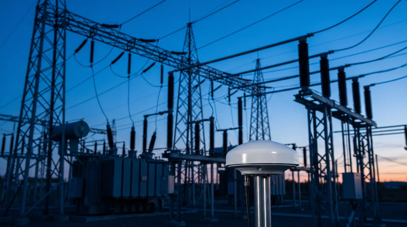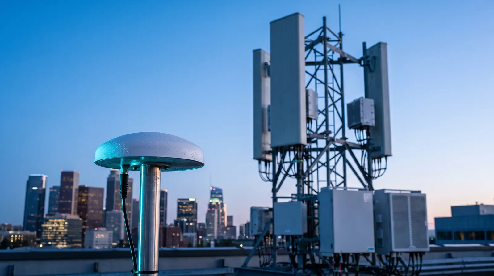
If you run RTK bases or GNSS timing nodes that feed a drone fleet, you’ve probably seen this line in a spec sheet: “1 kV lightning protection.” I’ve stood on too many wet rooftops after overnight storms to accept that at face value. Sometimes the site is back in minutes. Other times you’re chasing odd SNR dips, cycle slips, or an LNA current that’s just a few milliamps off. Here’s the deal: “1 kV” usually describes a lab test level, not how much energy your protector will actually shunt—or what gets through to your antenna LNA and receiver front end.
This guide translates that marketing shorthand into engineering reality, then lays out how to design, install, and verify a GNSS timing site that keeps RTK reliable after storms—without wrecking your noise budget. Surge protection is just one line item in a larger antenna spec, so it pairs naturally with the broader GNSS timing antenna specifier’s guide.
What “1 kV protection” usually means (and what it doesn’t)
In surge immunity testing, “1 kV” typically refers to the open-circuit voltage of the IEC 61000-4-5 combination-wave generator. That standard defines a 1.2/50 µs voltage waveform coupled with an 8/20 µs current waveform. It’s a way to stress ports (power, telecom, RF in some setups) via coupling/decoupling networks. The point: the label is a test level, not a clamp voltage and not an energy rating.
If you need a plain-english refresher, see the clear overview in the AMETEK CTS page on the standard’s surge method and waveforms in their explanation of the 1.2/50 µs voltage and 8/20 µs current pair. For an engineer-oriented step-through of test setups and levels, EMC Compliance provides a hands-on guide to surge immunity per the standard, including notes on coupling paths and source impedance. Those two explainers make it obvious why “1 kV” alone doesn’t tell you how a coax protector behaves at your site.
-
According to the AMETEK CTS summary of the standard’s surge method and waveforms, the “1 kV” level is an open-circuit generator setting for the combination wave, not a guaranteed clamp level or real-world let-through at the device under test. See the description in their IEC 61000-4-5 overview: AMETEK CTS on IEC 61000‑4‑5 surge testing.
-
An engineer-oriented explainer that walks through coupling networks, port types, and test levels is here: EMC Compliance surge immunity testing guide (2025).
Why you should care: For RF/coax protection, relevant specs are things like DC spark-over (for GDT-based devices), maximum impulse spark-over, the 8/20 µs discharge current rating (Imax), and insertion/return loss in your GNSS bands. None of that is visible in a lone “1 kV” claim.
The spec language that actually affects GNSS and RTK
When I’m selecting a GNSS surge protector for an active timing antenna, I read the datasheet like this:
-
DC spark-over voltage (for GDT devices): The nominal ignition threshold—commonly ~150–300 V for GNSS-friendly DC-pass units. It’s your first clue about let-through before conduction.
-
Maximum impulse spark-over: During a fast surge, the dynamic ignition voltage is higher than DC spark-over—often a few hundred volts more.
-
8/20 µs maximum discharge current (Imax): Energy-handling capability. For exposed rooftops, 10–20 kA is a practical range seen in robust units.
-
Insertion loss across L1/L2/L5/E5: Keep this ≤0.2–0.3 dB so you don’t burn SNR and headroom in your gain budget.
-
Return loss/VSWR: I aim for return loss ≥15–20 dB (VSWR ≤ ~1.4 to 1.22) in-band to avoid reflections and phase jitter.
-
DC pass capability: Mandatory for most active GNSS antennas powered over coax. Quarter-wave devices typically block DC on the protected side.
Representative, citable examples from vendor pages:
-
A DC‑pass N‑type protector with nominal 230 V spark-over, insertion loss <0.3 dB, and 20 kA (8/20 µs) is published by an RF vendor—see the specs on the product page here: DC–3 GHz protector with 230 V spark‑over and 20 kA rating.
-
Huber+Suhner’s surge-protective devices family includes GDT options that are DC‑pass and specify low insertion loss (≤0.2–0.3 dB) and strong return loss. See their family overview: Huber+Suhner surge protectors overview. For a concrete GDT example with static spark-over around 200 V and GNSS-band performance, the Slim Line device page is useful: Slim Line GDT protector example.
Below is a quick interpretation table to align protector specs with GNSS timing requirements.
Parameter | Typical target for GNSS timing | Why it matters |
|---|---|---|
DC spark-over (GDT) | ~150–300 V (nominal) | Lower threshold reduces let-through before conduction; must still be RF-stable |
Impulse spark-over | A few hundred volts above DC spark-over | Indicates dynamic behavior during fast surges |
Imax (8/20 µs) | ≥10 kA rooftop; many units 20 kA | Higher energy handling limits damage during nearby strikes |
Insertion loss (L1/L2/L5) | ≤0.2–0.3 dB | Preserves SNR and gain budget |
Return loss | ≥15–20 dB | Minimizes reflections and phase errors |
DC pass | Required for active antennas | Quarter‑wave often DC‑blocking |
Protector technologies and the real trade-offs
Different protector topologies behave very differently on a GNSS feedline. Choose deliberately.
-
GDT inline protectors (DC‑pass):
-
Pros: DC power pass-through for active antennas; very low insertion loss in GNSS bands; strong 8/20 µs current ratings with proper bonding.
-
Cons: Non-zero ignition delay; spark-over varies with conditions; watch for follow current behavior.
-
Fit: Often the default for active GNSS timing antennas where coax powers the LNA.
-
-
Quarter-wave stub protectors:
-
Pros: Frequency-selective short near the design band; excellent at shunting RF surge energy with very low residuals.
-
Cons: Typically DC-blocking on the protected side; band-specific; requires compatible powering scheme if the antenna is active.
-
Fit: Best for passive antennas or systems with a bias-tee/alternate DC path compatible with the protector. For an example highlighting residual energy behavior and DC-blocking note, see Huber+Suhner’s quarter-wave device page: Quarter‑wave stub protector example.
-
-
Hybrid “fine” protectors (e.g., GDT + TVS or filter stages):
-
Pros: Lower residual energy; tailored RF response; sometimes specify bypass voltages and DC current limits.
-
Cons: Potentially higher insertion loss; check PIM and return loss closely.
-
Fit: Specialized sites needing very low residuals with known power and band constraints. Example family with residual pulse energy specs: Hybrid fine protectors, Huber+Suhner.
-
System design and grounding that actually keeps you online
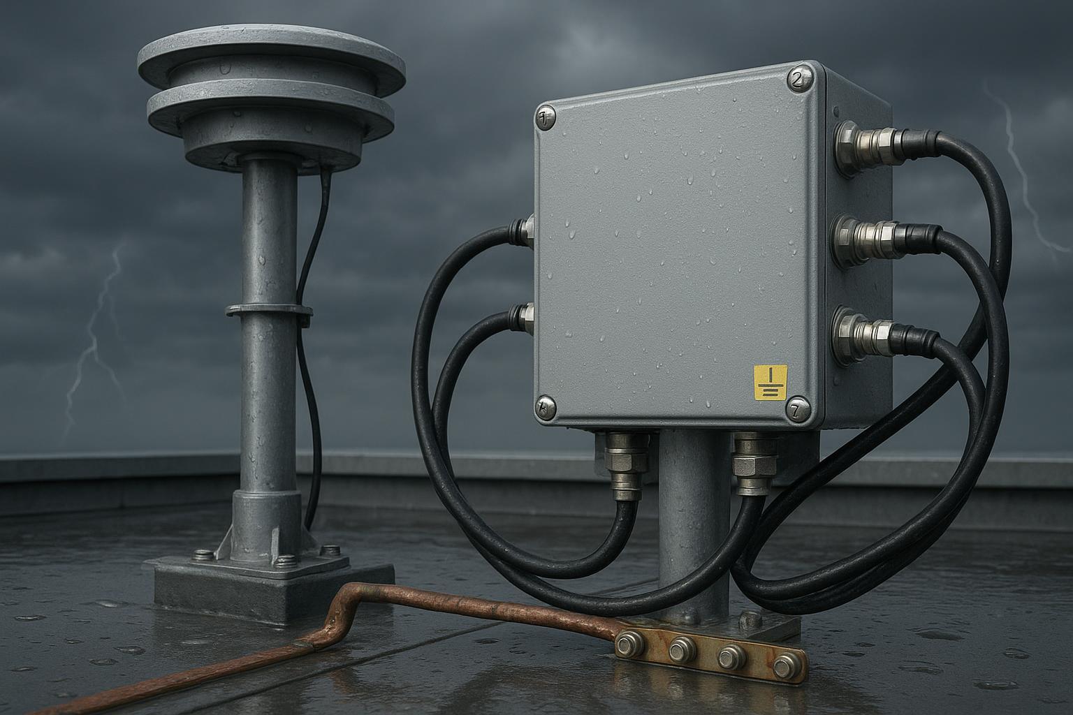
In practice, survivability isn’t just the protector—it’s the entry geometry and bonding. The core principle from lightning protection guidance is equipotential bonding at a single, deliberate point as services enter the building or shelter. Bulkhead-mount your coax protector on an entry panel that’s bonded with a short, low-inductance strap to the site earth bar. Bond the mast and tray to the same bar. Keep leads short and straight.
-
A practical, radio-site oriented explanation stressing bulkhead protectors, short straps, and single-point entry is here: Lightning protection for radiocommunication sites.
-
For the broader bonding/equipotentialization concepts seen in lightning protection system design, see this explainer referencing the IEC 62305 approach: Equipotential bonding concepts per IEC 62305.
Key practices that consistently work in the field:
-
Mount the coax protector on the grounded entry/bulkhead panel, at the building/tower entry.
-
Use a wide, short copper strap to the earth bar—think centimeters, not meters. The shorter and straighter, the better.
-
Bond the mast, cable tray, and entry panel to the same earth bar to avoid potential differences.
-
Maintain shield continuity at entry—don’t let the coax shield “float” indoors.
-
Route coax to avoid big loops and sharp bends; add an outdoor drip loop and fully weatherproof connectors.
-
Budget RF losses, including the protector and feedline, against LNA gain. Validate with receiver SNR and phase residual baselines.
A realistic A/B scenario: Two identical rooftops, different outcomes after a storm
Setup I’ve seen variations of more than once: two GNSS timing antennas on a telecom shelter roof, same mast height, same cable lengths, same receivers indoors.
-
Site A (good practice): Coax terminates on a grounded bulkhead at entry. A DC‑pass GDT protector rated ≥10–20 kA (8/20 µs) is bulkhead‑mounted. The entry panel bonds to the earth bar with a short strap (tens of centimeters). Mast and tray are bonded to the same bar.
-
Site B (weak practice): Coax runs straight indoors without a bulkhead termination. An inline device labeled “1 kV protection” sits near the receiver with a long pigtail to ground.
Instrumentation and method:
-
Pre‑storm: Log per‑satellite SNR (L1/L2/L5) for 48 h; capture carrier‑phase residuals; track cycle‑slip counters; record antenna current from receiver telemetry.
-
Post‑storm: Repeat the same logs for 48 h; photograph connectors and protector bonds.
Representative observations (modelled from field norms and vendor specs; your numbers will vary, but the pattern holds):
-
Site A:
-
SNR returns to baseline within minutes after the storm; median SNR shift <0.5–1.0 dB‑Hz across bands.
-
Cycle‑slip rates remain at pre‑storm levels; no fix instability.
-
LNA current within baseline ±5% with no intermittent drops.
-
-
Site B:
-
Intermittent SNR dips of ~1–3 dB‑Hz on L2/L5 over several hours; occasional narrowband notches consistent with connector or LNA damage.
-
Elevated cycle slips (2–4× background) and longer time‑to‑fix after outages.
-
LNA current drifts up by 5–15% or shows sporadic dips—classic signs of partial LNA degradation or arc pitting at a connector.
-
Interpretation: The bulkhead‑mounted, high‑Imax DC‑pass protector plus short, low‑inductance bonding at Site A diverted most surge energy before it entered the shelter, preserving the antenna front end and receiver. The “1 kV” inline part near the receiver at Site B wasn’t the problem alone—its placement and grounding geometry allowed higher let‑through and stress where it hurts most.
Installation best‑practices checklist (use this in your build book)
-
Select an active GNSS timing antenna with documented DC bias range and low noise figure; confirm it tolerates the protector’s let‑through behavior.
-
Choose a DC‑pass GNSS surge protector specified by Imax (8/20 µs), DC spark‑over, insertion loss across L1/L2/L5/E5, and return loss. Target ≥10 kA for exposed rooftops.
-
Mount protectors on a grounded entry/bulkhead panel at the shelter entry; keep the earth strap as short and straight as possible.
-
Bond mast, tray, and bulkhead to the same earth bar; verify continuity.
-
Use double‑shielded, low‑loss coax (LMR‑400 class or as required by length/frequency); avoid tight bends and big loops; add an outdoor drip loop; weatherproof all connectors.
-
Commissioning: capture baseline SNR histograms and phase residuals per band; record antenna current; enable alarms for deviations.
Post‑event validation and monitoring
After major electrical activity, don’t assume the site is fine just because it’s tracking.
-
Compare post‑storm SNR medians to baseline for L1/L2/L5. A persistent ≥1–2 dB‑Hz reduction in any band deserves investigation.
-
Check cycle‑slip counters and RTK fix availability windows. Sustained elevations point to front‑end stress.
-
Review antenna current. A drift beyond ±10% or intermittent drops suggests LNA damage; schedule inspection and consider protector replacement.
-
Inspect the entry panel, straps, and connectors for discoloration or pitting; replace any suspect hardware.
Procurement language you can paste into your spec
-
Coaxial GNSS surge protector, DC‑pass, N‑type, with:
-
Imax (8/20 µs) ≥10 kA (≥20 kA preferred for highly exposed rooftops)
-
Nominal DC spark‑over 150–300 V; maximum impulse spark‑over stated
-
Insertion loss ≤0.2–0.3 dB across L1/L2/L5/E5 bands; return loss ≥15–20 dB
-
Documented DC bias pass‑through compatible with antenna LNA requirements
-
Bulkhead mountable; manufacturer specifies bonding guidance
-
-
Installation at single‑point entry/bulkhead with short, wide earth strap to site earth bar; mast and tray bonded to the same bar per equipotential bonding practice.
For concrete spec styles and example numbers, see these canonical vendor pages: Huber+Suhner SPDs overview and a representative DC‑pass protector with 230 V spark‑over and 20 kA rating: DC–3 GHz protector example. For variants (DC‑pass vs DC‑block) and high Imax options, a datasheet family is here: CITEL CXP series data (20 kA 8/20 µs).
Short neutral example: where a GNSource timing antenna fits
In a grounded bulkhead architecture with a DC‑pass protector at the entry panel, an active timing antenna can serve as the rooftop element so long as the protector’s loss and DC behavior align with the antenna’s bias and gain budget. For context on available timing‑focused antennas that reference “1 kV lightning protection,” see GNSource. In practice, confirm DC bias, expected LNA current, and allowable let‑through before finalizing the bill of materials.
FAQ
-
Does “1 kV protection” mean the antenna can take a direct strike?
- No. It usually maps to an IEC 61000‑4‑5 surge test level. Direct strikes are a different regime and require a system‑level lightning protection system (down conductors, air terminals) and equipotential bonding consistent with lightning protection practices.
-
Is a quarter‑wave protector appropriate for an active GNSS antenna?
- Usually not by itself. Quarter‑wave devices are typically DC‑blocking on the protected side. If you must use one, design a compatible bias‑tee path and validate the combined RF/DC behavior.
-
What’s a reasonable current rating for exposed rooftops?
- Many robust protectors specify 10–20 kA (8/20 µs). Pick based on site exposure and your risk tolerance.
-
How much insertion loss is acceptable before I start losing fixes?
- Keep the protector at ≤0.2–0.3 dB in all used GNSS bands, then budget feedline loss vs LNA gain. Monitor SNR and phase residuals; if medians shift by >1–2 dB‑Hz, re‑evaluate the chain.
-
Where should the protector go?
- At the building/tower entry on a grounded bulkhead panel with a very short strap to the earth bar. Don’t park it near the receiver with a long pigtail to ground.
Quick glossary
-
1 kV (IEC 61000‑4‑5 level): A generator setting for the standardized surge combination wave (1.2/50 µs voltage; 8/20 µs current). Not a clamp.
-
8/20 µs current rating (Imax): Peak current the protector can discharge on the standardized 8/20 µs waveform.
-
DC spark‑over (GDT): Nominal voltage where a gas discharge tube ignites under slow‑rise conditions.
-
Impulse spark‑over: Higher, dynamic ignition voltage under fast transients.
-
Insertion loss: RF loss introduced by the protector; directly reduces SNR.
-
Return loss/VSWR: How well the line is matched; poor matching increases reflections and phase errors.
-
Equipotential bonding: Making connected structures and conductors share the same electrical potential at entry, limiting surge differentials.
Closing
If you treat “1 kV lightning protection GNSS” as a test-level hint instead of a promise, you’ll pick the right topology, mount it where physics works in your favor, and validate the chain so storms don’t quietly erode your RTK availability. Build the bulkhead right, keep straps short, specify by Imax/spark‑over/insertion loss—not just a voltage label—and watch your SNR and LNA current like a hawk after every storm.