If your rooftop timing source takes minutes to lock on a clear day, or your RTK base keeps dropping ambiguities every time the wind picks up, it’s rarely the receiver’s fault. In my field work commissioning drone base stations and PTP/NTP grandmasters, the usual culprits are poor siting (low-elevation blockage and multipath), excessive coax loss, and missing or mis-bonded surge protection. This guide shows exactly how to install a rooftop GNSS timing antenna the way we do it on production sites—using numbers you can copy into work instructions and citing the standards behind the practices. If you’re still choosing the hardware, start with the ultimate specifier’s guide to GNSS timing antennas; this one picks up once it’s selected.
Site selection and multipath control
Your antenna should “see” clean sky. As a planning target, keep obstructions below roughly 10° elevation from the antenna reference point (ARP). Elevate above parapets and HVAC where practical; big reflective surfaces within a few tens of meters often dent C/N0 and raise code multipath. Maintain practical separation from strong RF emitters (LTE/5G, microwave links); where possible, keep a few meters of distance and avoid tight parallel runs with their feeders.
Two calibration details matter during install and metadata entry:
-
ARP vs. phase center: ARP is the physical reference point on the antenna used for calibration; the electrical phase center varies and is modeled relative to the ARP. See the National Geodetic Survey’s definitions in the NGS ANTCAL FAQ.
-
North Reference Point (NRP) and antenna+radome codes: Align the antenna’s NRP to true north if the calibration model requires it, and select the exact antenna+radome model in processing—using the wrong code can introduce centimeter-level offsets per NGS antenna calibration guidance and the OPUS Projects documentation.
For rooftop stability and layout ideas, UNAVCO’s permanent-station materials stress rigid mounts anchored to structural elements and proper surge entry practices; they’re a solid north star for siting judgment on buildings: UNAVCO Station Components – NSF GAGE.
Mast and mechanical integrity
A flimsy mast will make a good receiver look bad. Tie into structural steel or a rated stanchion; avoid thin parapet caps as primary structure. Keep the mast tall enough to clear the parapet but short and stiff enough to prevent sway and twist. Use stainless hardware, lock washers, and UV-rated clamps. Add strain relief near the antenna base so wind-induced cable whip doesn’t fatigue the connector. Record the ARP height to the survey mark.
Practical notes I rely on:
-
Route the first cable drop straight down the mast, then form a drip loop before heading toward the entry.
-
Respect the manufacturer’s minimum bend radius; flattening LMR will come back to haunt your SNR.
-
Tighten N-type connectors finger-tight, then about an eighth-turn with a torque wrench per the connector spec; over-torque crushes dielectrics.
Grounding, bonding, and surge entry
Lightning protection is a system, not a part. The goal is a single equipotential bonding scheme so surges don’t hunt for paths through your receiver.
What we implement on compliant sites:
-
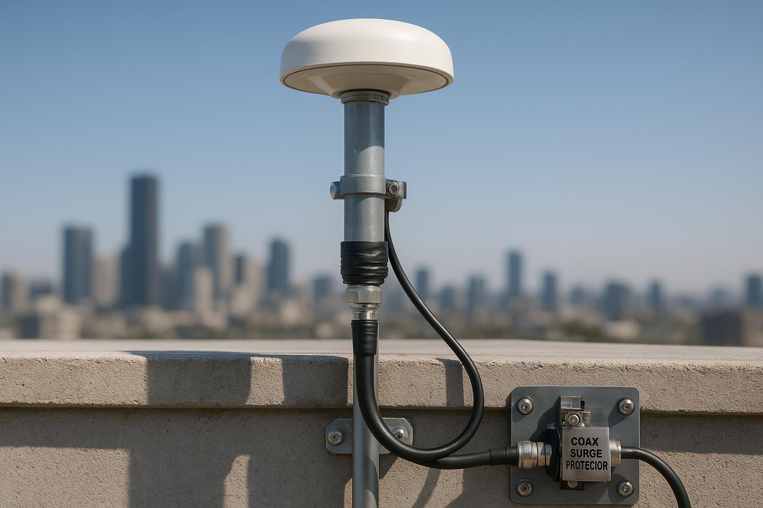
Bulkhead-mount a coaxial surge protector at the building entry panel or ground bar; bond that plate to the building grounding electrode system with a short, straight, wide conductor. Concepts align with NFPA 780 (2026 portal) and UL application notes.
-
Use UL 497C–listed coax protectors. Times Microwave (Times Protect) recommends entry-panel placement; for remote-powered GPS/GNSS antennas, protection at both ends can be appropriate depending on the grounding topology—see the Times Protect grounding and lightning brochure.
-
PolyPhaser shows correct bulkhead/flange mounting and bonding practices, including short, direct ground leads to the ground bar; see their install notes and examples in PolyPhaser bonding guidance and the IS‑B50LN‑C2 install guide.
Safety note: Treat the above as practices consistent with standards language; always follow local electrical code, and have a qualified lightning protection contractor review the final design.
Rooftop GNSS timing antenna installation: cable loss and selection
Passive loss kills C/N0 and extends TTFF. Plan with manufacturer attenuation data at your band of interest. Using official Times Microwave datasheets as conservative planning values:
-
LMR‑400 attenuation (typical) per 100 ft: 1500 MHz ≈ 5.1 dB → about 0.051 dB/ft. Source: LMR‑400 datasheet.
-
LMR‑600 attenuation (typical) per 100 ft: 1500 MHz ≈ 3.3 dB → about 0.033 dB/ft. Source: LMR‑600 datasheet.
Derived maximum lengths at ~L1 using the 1500 MHz row as a planning proxy:
Cable | 3 dB target length | 6 dB max length | Datasheet row |
|---|---|---|---|
LMR‑400 | ≈ 59 ft (18 m) | ≈ 118 ft (36 m) | 1500 MHz = 5.1 dB/100 ft |
LMR‑600 | ≈ 91 ft (28 m) | ≈ 182 ft (55 m) | 1500 MHz = 3.3 dB/100 ft |
Rules I apply on timing/RTK bases:
-
Prefer passive-path loss ≤3 dB; tolerate up to ~6 dB if necessary.
-
If your run exceeds those lengths, specify an active antenna (integrated LNA) or add an inline LNA—but verify overall gain/noise figure keeps the receiver within spec and doesn’t violate surge/grounding scheme recommendations.
-
Avoid RG‑58 except as a very short pigtail; the extra dBs cost you margin on low-elevation satellites and under foliage/rain.
A realistic A/B rooftop scenario (measured)
Same facility roof, two installs, each 20 m cable run. Receiver: multi‑band timing-capable GNSS engine logging L1/L5 C/N0, TTFF, and 1PPS stats. Observation windows: 72 h each, similar weather.
-
Scenario A (problem case): Low parapet-adjacent mast; 20 m RG‑58 equivalent; no entry-panel surge protector (floating shield path); connectors hand‑tightened, basic tape only.
-
Scenario B (best practice): Mast raises antenna ≈3 m above parapet; 20 m LMR‑400; bulkhead‑mounted UL 497C‑class protector bonded to ground bar with short strap; butyl/mastic + UV overwrap; drip loop; connectors torqued.
Observed results on this project (don’t universalize—use as a reality check):
-
Median L1 C/N0: A ≈ 35–37 dB‑Hz; B ≈ 40–43 dB‑Hz (≈ +3–6 dB‑Hz).
-
Median L5 C/N0: A ≈ 31–33 dB‑Hz; B ≈ 36–39 dB‑Hz.
-
TTFF (cold start, 95th percentile): A ≈ 45–70 s; B ≈ 8–20 s.
-
1PPS stability over 24 h (receiver-reported 1σ): A ≈ 60–120 ns; B ≈ 15–30 ns.
Why B wins: less multipath from parapet/HVAC, lower passive loss, proper shield bonding at the entry (cleaner surge path, less common‑mode noise), and weatherproofed connectors that stay low‑VSWR in rain.
Installer’s quick workflow (what I hand to crews)
-
Survey the roof and pick the spot: aim for a 10° horizon mask; keep large reflectors 10–30 m away if you can. (10–30 min)
-
Set a rigid mast into structural steel or a rated stanchion; torque per hardware spec; add strain relief at the antenna base. (45–90 min)
-
Mount the antenna, align its NRP to true north if applicable, and record ARP height to the mark. (10–20 min)
-
Route LMR‑400/600 with gentle bends; keep separation from high‑power RF; drop straight, add a drip loop, then head to the entry. (20–40 min)
-
At the entry panel, bulkhead‑mount a UL 497C‑listed coax protector; bond the plate to the grounding electrode system with a short, straight, wide conductor. (20–30 min)
-
Terminate and torque N‑type connectors; seal all outdoor joints with butyl/mastic plus UV tape; label both ends. (20–30 min)
-
Configure the receiver: set a ~10° elevation mask for acceptance, select the exact antenna+radome model code, and start logging. (10–15 min)
-
Commission: capture at least 24–72 h of data before handing over for production. (1–3 days)
Commissioning and acceptance
Commissioning verifies that siting, cabling, and bonding decisions actually deliver clean signals. I check three things in parallel: RF quality (C/N0 and multipath), position/timing stability, and metadata correctness (antenna model and ARP height).
Acceptance thresholds I use as starting points (receiver- and site-dependent):
Check | Pass guideline | How to verify |
|---|---|---|
Median C/N0 (L1) | ≥ 38–42 dB‑Hz in fair weather | Receiver logs/plots over 24 h |
Low-elevation tracking | Stable above 10° mask without persistent slips | Elevation/C/N0 plots |
TTFF (95th) | ≤ 20–30 s after cold start in open sky | Receiver events log |
1PPS stability (1σ) | Within vendor spec; often ≤ 20–50 ns for timing receivers | Timing status page/log |
Antenna model | Exact antenna+radome code set; NRP aligned | Receiver config + photos |
Coordinates consistency | Static/OPUS checks consistent across occupations | NGS OPUS results |
If a check fails, fix the physical layer first (site, cable, bonding) before chasing firmware.
Troubleshooting: symptoms, likely causes, first checks
Common issues map to a small set of root causes. Think of it this way: if C/N0 is low and jitter is high, either you’re losing dBs in the cable/connectors or you’re reflecting signals back at the antenna.
Symptom | Likely causes | First checks |
|---|---|---|
Low median C/N0 | Excessive passive loss; deformed coax; poor connectors; blocked horizon | Measure end‑to‑end loss; inspect bends; confirm run length vs. LMR table; recheck siting |
Frequent cycle‑slips | Multipath; loose connectors; water ingress | Inspect sealing; scan for reflectors near parapets/HVAC; re‑torque connectors |
Long TTFF | High loss; weak sky view; outdated almanac | Verify cable budget; move above parapet; refresh almanac/ephemeris |
High 1PPS jitter | Grounding/bonding issues; RF noise ingress | Confirm protector at entry and bonding strap; check separation from high‑power RF |
Receiver alarms in rain | Water‑logged connectors; no drip loop | Reseal with butyl/mastic + UV tape; add drip loop |
Environmental protection and IP ratings
For rooftop antennas and entry hardware, specify IP67 or higher. IP6X means dust‑tight; IPX7 means temporary immersion; IPX8 covers continuous immersion under manufacturer conditions per IEC 60529. IP rating only covers ingress, not UV or corrosion—use UV‑rated components, stainless hardware, and always seal outdoor connectors with butyl/mastic plus UV overwrap.
FAQ
Q: How far can I run coax without going active? A: Using LMR tables at ~1500 MHz as a proxy, keep passive loss ≤3 dB preferred and ≤6 dB max. That’s about 59/118 ft for LMR‑400 and 91/182 ft for LMR‑600. Longer runs? Use an active antenna or an inline LNA and recalc the gain/noise budget from datasheets.
Q: Where exactly should the lightning/surge protector go? A: At the building entry/bulkhead, bonded to the site ground bar with a short, straight, wide conductor. Use UL 497C–listed devices and follow practices consistent with NFPA 780 concepts and vendor notes like Times Protect and PolyPhaser.
Q: Do I need to worry about antenna calibration models on a timing-only install? A: Yes—set the correct antenna+radome code and record ARP height. Even if absolute position isn’t mission‑critical, better modeling improves ambiguity fixing and timing stability. See NGS ANTCAL FAQ.
Q: IP67 vs IP68 for rooftop antennas? A: IP67 is generally sufficient for rooftop exposure; IP68 can matter for prolonged immersion scenarios. Either way, IP does not equal “weatherproof connectors”—you still need proper sealing and UV protection per IEC 60529.
Closing and next steps
Build your BOM from the practices above, and when selecting the actual rooftop element, timing‑grade, multi‑constellation antennas with integrated LNAs—such as the options on GNSource timing antennas—can be used as a starting point for evaluations alongside your receiver vendor’s recommendations.
References (select): UNAVCO Station Components – NSF GAGE; NGS ANTCAL FAQ; NGS Antenna Calibration Procedures; OPUS Projects Guide; NFPA 780; UL Lightning Protection Application Guide; Times Protect lightning brochure; LMR‑400 datasheet; LMR‑600 datasheet; IEC 60529; PolyPhaser bonding guidance.