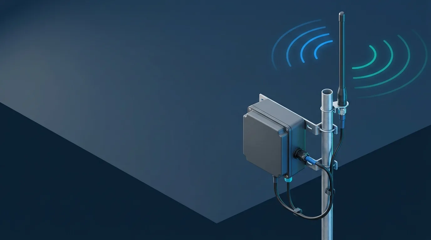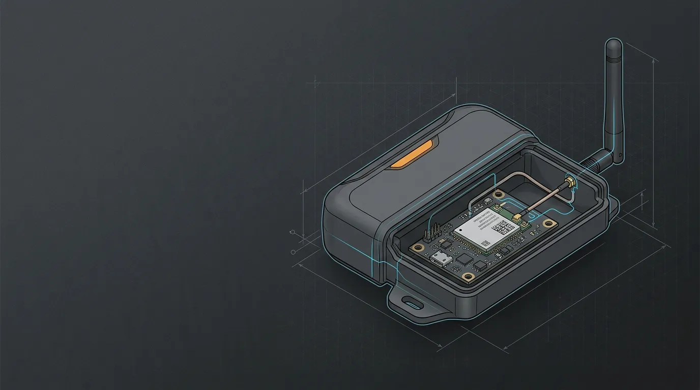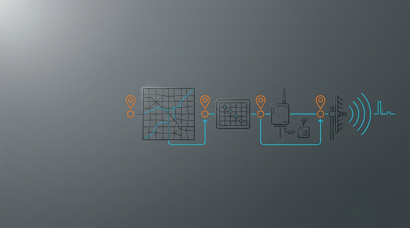
A LoRaWAN antenna for 868 MHz versus 915 MHz is not an interchangeable accessory by default. First choose the regional LoRaWAN plan and the radio configuration permitted for the deployment. Then verify that the antenna’s measured frequency range, return loss or VSWR, pattern, connector and installation conditions cover the frequencies actually used. A label that says “868/915” is a starting claim to test, not a universal approval. The IoT antenna buyer’s guide provides the wider radio-first framework.
Choose the region and LoRaWAN plan before the antenna
The radio’s regional plan and the antenna’s electrical bandwidth are separate checks. The first decides which frequencies and operating parameters the device is designed to use in a particular deployment. The second decides whether the antenna can radiate and receive efficiently across those actual frequencies. Passing one check does not pass the other.
For a LoRaWAN project, record the deployment country, the selected regional plan, module/firmware region, network-server configuration and any applicable local approval path before purchasing RF hardware. The LoRa Alliance maintains current LoRaWAN Regional Parameters technical specifications, including the regional-plan document family. Use the current version for the release, not an old marketplace table or a continental shorthand.
This article deliberately does not turn that into a country-by-country legal chart. Regulations and permitted operating details are deployment-specific and change over time. Confirm them with current local requirements and the relevant authority or certified device documentation. An antenna that covers 902–928 MHz does not make a radio lawful in a location where its configuration is wrong; conversely, a correctly configured radio still needs an antenna that covers its channels.
| Decision layer | Question to answer | Evidence to retain |
|---|---|---|
| Deployment | Where will this unit operate? | Country/site list and intended markets. |
| LoRaWAN radio plan | Which current regional plan and device configuration apply? | Module and network-server documentation; current regional-parameter reference. |
| Antenna electrical fit | Does the candidate cover every operating frequency with stated performance? | Datasheet curves or test data across the actual band. |
| Installation fit | Will the installed pattern, cable and mounting preserve that performance? | Mounting drawing, cable loss, connector and environment specification. |
Why 868 MHz and 915 MHz require different antenna checks
The difference is real in RF terms. Frequency changes wavelength, physical antenna dimensions and the part of the spectrum where matching must be verified. A simple quarter-wave reference is roughly 8.6 cm at 868 MHz and 8.2 cm at 915 MHz before end effects, loading, ground-plane interaction, housing and the feed are considered. It helps explain why these antennas are compact; it is not a cut-length instruction or a design acceptance test.
An antenna’s useful bandwidth is the important field. Ask for a specification or measured plot that covers the intended operating frequencies, rather than selecting by a centre-frequency label. Return loss and VSWR describe how well the feed is matched over frequency; they need to be read alongside radiation pattern, realized gain, polarization, connector and the stated test ground plane. A very narrowband antenna may be excellent at one centre frequency and unsuitable at the other. Cisco’s LPWA antenna-installation guidance is a useful manufacturer example of why the antenna’s intended radio, gain/pattern and installation documentation must be read together. The 433 MHz antenna guide is an adjacent example of how sub-GHz wavelength, form factor and installation interact; it is not a substitute band for an 868 MHz or 915 MHz LoRaWAN deployment.
| Antenna claim | What it proves | What it does not prove |
|---|---|---|
| “868 MHz” | The maker intends a design near that band | That it is efficient across a 915 MHz deployment. |
| “915 MHz” | The maker intends a design near that band | That it covers the European plan or another regional configuration. |
| “868/915 dual-band” | A possible multi-band candidate | That both bands meet your return-loss, pattern and gain needs without current data. |
| “Wideband sub-GHz” | A wider claimed frequency span | That the form factor, enclosure and cable will perform unchanged when installed. |
Can one antenna cover both bands?
Yes, a deliberately designed dual-band or broadband antenna can cover both frequency regions, but compatibility must be demonstrated by the actual product data. It is not created by using a 915 MHz part in an 868 MHz system, or by treating a tuned whip as a universal sub-GHz radiator.
Before accepting a common antenna for two product variants, request the following:
- The specified frequency range and measured return-loss/VSWR data over every required operating range.
- Gain and radiation-pattern data, including polarization and the test ground-plane or fixture.
- The device enclosure, mounting surface and cable/connector configuration used for validation.
- A statement of whether the part is gateway-, end-device- or general-installation oriented.
- The revision-controlled part number, connector option and environmental evidence for production.
The practical rule is narrow: bandwidth and data-sheet verification matter more than a printed frequency label. For production hardware, take the next step and validate the candidate in the real enclosure. Metal, batteries, a cable shield or a different ground plane can change the match.
Select for a gateway or an end device
A gateway and a sensor node face different installation constraints. A fixed outdoor gateway may need broad azimuth coverage across many nodes, an elevated mast, a weatherproof feed and an intentional grounding/surge design. A compact end device may need a short whip, an embedded element or a panel-mount solution that survives a battery, enclosure and handling conditions. Neither role is “better”; they require different evidence.
| Deployment role | Selection priority | Practical checks |
|---|---|---|
| Outdoor gateway with nodes in many directions | Omnidirectional coverage, mast/connector weather protection, a manageable feed loss | Height and vertical beamwidth, cable entry, pole load, local grounding/surge design. |
| Fixed gateway with nodes mainly in one direction | Directional or sector pattern where geometry supports it | Aim method, polarization, pattern coverage and field-test points. |
| Indoor or cabinet-mounted gateway | Move the antenna clear of RF-hostile surfaces where possible | Feed-through, enclosure detuning, cable length and separation from noisy electronics. |
| Battery or compact end device | Mechanical fit and the real ground plane before headline gain | Enclosure material, user grip/orientation, battery interaction and strain relief. |
| Vehicle or serviceable field unit | Serviceability and mounting stability | Cable flex, mounting material, ingress and repeatable orientation. |
For a fixed outdoor gateway that needs broad horizontal coverage, compare outdoor fiberglass omni antenna options only after the regional-frequency and site-geometry checks are complete. Where frequent removal or vehicle/service access matters, the magnetic-mount versus permanent-mount guide helps frame the ground-plane and cable-routing decision. Cisco’s LPWA installation guidance also treats antenna placement and the surrounding installation as part of the system, rather than as a connector-only purchase. Both are form-factor resources; neither can replace a regional-band check.
Treat range as a system result, not a band promise
It is tempting to ask how far 915 MHz will reach, but a kilometre number without conditions is not an antenna specification. The result depends on radio settings, conducted power, receiver sensitivity, two installed antenna systems, cable and connector loss, antenna height, polarization, terrain, foliage, clutter and interference. A gateway on a clear mast and a low sensor beside metal are not comparable installations even if both use the same nominal band.
Use a link budget to state assumptions and preserve margin rather than promising distance. The IoT antenna link-budget guide shows how realized gain and feedline loss enter the calculation, and why a longer cable can spend the gain added by a larger antenna. Test the finished installation at representative worst-case positions and orientations. Record packet delivery and radio-quality measurements with the antenna and enclosure actually being released; Semtech’s LoRa Cloud documentation identifies RSSI and SNR as per-gateway-antenna reception fields, making them useful fields to retain alongside the installation record.
If a field result is poor, inspect matching, the cable assembly, connector mating, mounting surface, height, polarization and obstruction before moving to a higher-gain part. Those variables are frequently cheaper to correct and can change more of the system margin than a product label suggests.
Put the right inputs in the RFQ
An antenna supplier can assess a LoRaWAN deployment only when the request identifies the radio, region and installation. This is a useful procurement checklist:
| RFQ field | What to provide |
|---|---|
| Deployment region | Country/site list and intended markets |
| Radio and plan | Module, firmware region and the applicable LoRaWAN regional-plan reference |
| Role | Gateway, end device, vehicle or another installed role |
| Frequency need | Required operating frequency ranges, not only “LoRa” |
| Electrical evidence | Target impedance, return-loss/VSWR expectation, gain/pattern/polarization requirement |
| Physical integration | Enclosure material, ground plane, mount, height and orientation |
| Feed path | Connector family/gender, coax type/length, adapters and entry sealing |
| Environment | Indoor/outdoor, UV, vibration, temperature, dust, salt, wash-down and service access |
| Programme | Prototype/production quantity and installed validation plan |
Unknown values are useful information when labelled honestly. They point to the test that must happen before a release. Contact GNSource Engineering with this record to review an antenna architecture or an OEM RFQ.
Frequently asked questions
Are 868 MHz and 915 MHz antennas interchangeable?
Not by default. A dual-band or broadband antenna may be appropriate when its measured electrical performance covers every required operating range, but a single-band product must not be assumed to work efficiently at the other frequency. The LoRaWAN regional plan and applicable local rules are a separate prerequisite.
What is the best antenna for a LoRaWAN device?
Choose by the deployment role and evidence, not a generic “best” label. Start with region and operating frequencies, then match the antenna bandwidth, pattern, polarization, connector, cable, mounting surface and environment. A gateway may need a mast-mounted omni or directional system; a compact end device may need a solution validated in its own enclosure.
How far can a 915 MHz LoRaWAN link reach?
There is no universal distance. It depends on radio settings, allowed configuration, antennas, cable loss, height, terrain, obstructions, interference and the required reliability. Build a two-way link budget and validate the intended installation instead of relying on an open-field headline range.
Is 915 MHz legal in the United States?
US deployments must use a device configuration and operating method that meet the current applicable requirements. Confirm the module’s regional configuration, current LoRaWAN Regional Parameters and relevant US regulatory obligations for the actual product and use case. The FCC’s Office of Engineering and Technology Knowledge Database is an official entry point for equipment-authorization procedures and measurement guidance; use it with the product’s actual certification documentation rather than treating a generic antenna article as a compliance approval. An antenna selection article cannot certify legal operation.
How long should a 915 MHz antenna be?
A quarter-wave reference is about 8.2 cm at 915 MHz, but the final electrical length depends on the antenna design, loading, feed, enclosure and ground plane. Use the selected antenna’s data sheet and measured performance; do not cut or approve a production antenna from the quarter-wave number alone.