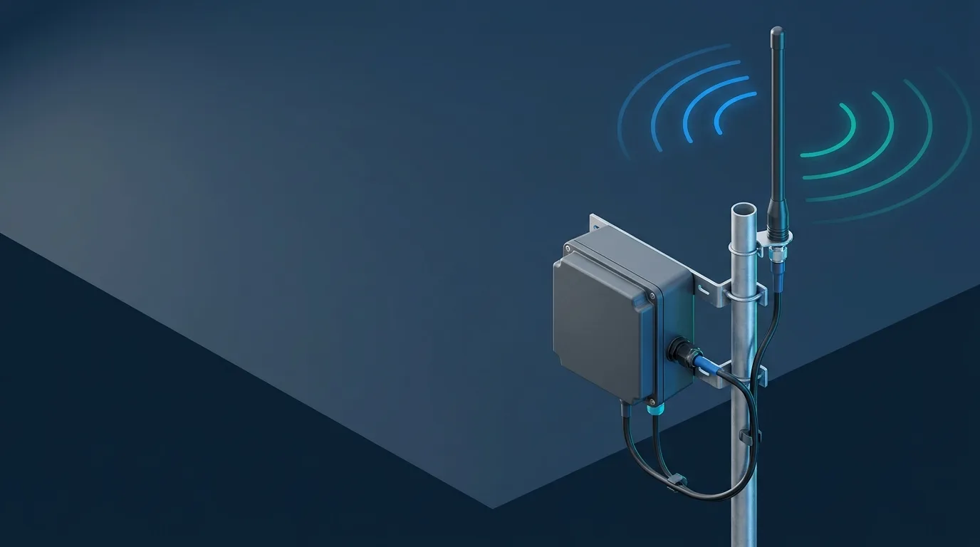
An outdoor LoRaWAN gateway antenna setup is not complete when an antenna is mounted on a mast. The gateway’s regional plan and LoRa port, antenna band and pattern, feeder path, weather entry, site conditions and a representative field test all have to agree. The best position balances useful radio exposure, cable loss, service access and a maintainable installation; it is not a universal height or gain number.
Use this guide to prepare an installation and commissioning record for an industrial gateway. It does not set local radio limits, certify an outdoor electrical installation or replace a site-specific lightning-protection design. Start with the radio-first IoT antenna selection framework if the radio, region or deployment objective has not been confirmed.
Start with the gateway radio, regional plan and port map
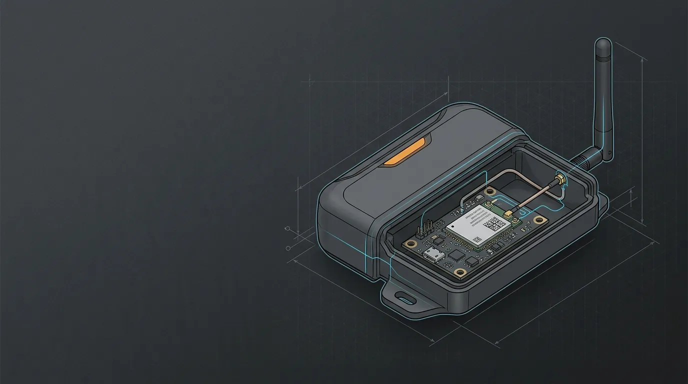
Before choosing a mast, identify the exact gateway model, hardware/region variant, LoRaWAN frequency plan and documented LoRa antenna port. A gateway enclosure may also expose ports for GNSS, LTE, Wi-Fi or service functions; a physically similar connector is not evidence that it serves the LoRa radio.
Record the antenna’s operating range and intended pattern alongside the gateway’s active regional plan. For example, a deployment that uses US915 is not automatically compatible with an EU868 antenna, even if both products are described as “LoRa.” Use the regional LoRaWAN band verification workflow to collect the module/gateway evidence before installing anything.
The The Things Outdoor Gateway documentation is one model-specific illustration of why this port map matters: its LoRaWAN, LTE and GPS functions have separate documented connections. Treat your own gateway manual as the controlling document, not another product’s connector layout.
The outdoor gateway installation and acceptance checklist
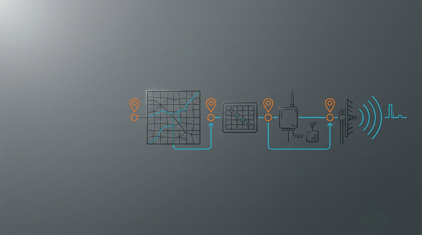
This is a sequence, not a list of optional accessories. A missing record at an early stage should stop the next purchasing or installation decision.
| Stage | What to document | Practical stop/go decision |
|---|---|---|
| 1. Gateway and radio | Exact model/variant, regional plan, LoRa port, firmware and backhaul/power owner | Stop if the radio path or regional configuration is not confirmed. |
| 2. Antenna system | Band coverage, pattern, connector, mounting orientation and intended service area | Stop if the antenna specification does not cover the active regional band or the proposed role. |
| 3. Site and mount | Proposed location, obstructions, mounting structure, service access, nearby metal and maintenance route | Proceed only when the mount is mechanically appropriate and accessible for inspection. |
| 4. Feedline | Coax family, length, both terminations, adapters/bulkheads, bend and strain path | Stop if the complete assembly or its installed route is unspecified. |
| 5. Weather entry | Enclosure entry, gland/connector instructions, downward route, drip path and post-install inspection | Proceed only when the entry remains protected after the cable is installed. |
| 6. Protection boundary | Bonding/grounding and surge-planning responsibilities, manufacturer instructions and qualified local review where needed | Stop if exposed-site protection is being assumed from a connector, ground lead or product label alone. |
| 7. Commissioning | Baseline, representative endpoint test locations, backhaul state, observations and corrective-action owner | Commission only after the same test can be repeated and recorded. |
This record complements the external antenna compatibility record for the device-side radio, ports and cable assembly. The difference is scope: that checklist verifies whether an RF path belongs together; this guide carries a confirmed LoRaWAN path into an outdoor site and acceptance process.
Choose a location without relying on a universal height rule
Higher placement can improve exposure above local obstacles, but it can also create a longer feeder run, harder service access, different mechanical loading and a more exposed cable route. A site with a shorter, better protected RF path may be the stronger project choice even when another point is physically higher.
Evaluate the proposed location against four questions:
- Does the antenna have reasonable clearance from nearby obstructions and surfaces that can alter its installed pattern?
- Can the mounting structure, cable route and enclosure be inspected and serviced without creating an uncontrolled installation task?
- Does moving the antenna add feeder length or adapters that consume useful RF margin?
- Can representative end devices be tested from the locations that matter for the deployment?
For fixed outdoor infrastructure, a fiberglass omni category may be appropriate after the band, pattern, connector and site role are confirmed. See fiberglass omni antennas for fixed outdoor infrastructure only after those checks; it is not a substitute for the site record.
Plan the feedline and inspect the complete RF path
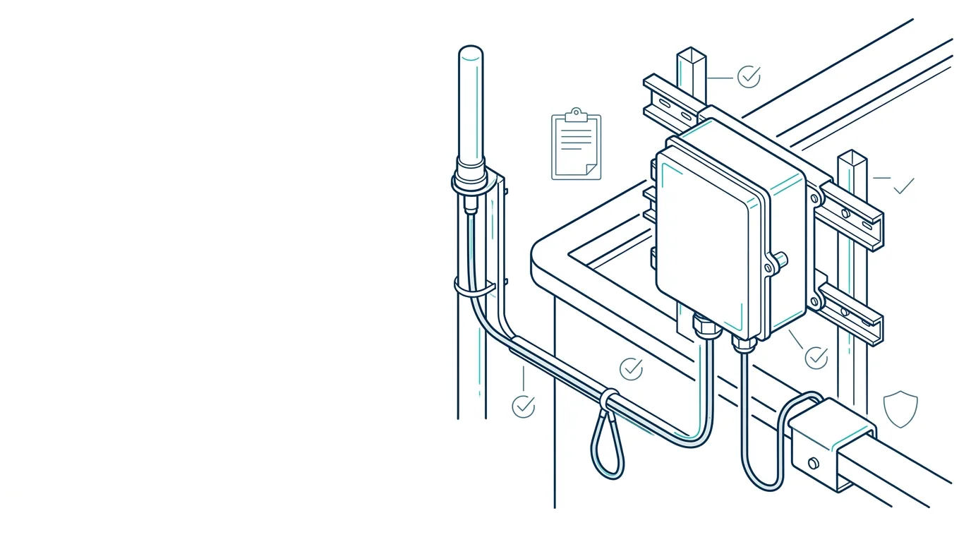
A feeder is part of the antenna system. Record the cable’s actual family and length, both connector ends, every bulkhead or adapter, its route, strain relief and exposure. Do not decide the cable only by what is convenient to route on installation day.
The trade-off is between antenna location and installed loss. A remote antenna can improve exposure, while a long cable run and extra interfaces can reduce the margin you expected to gain. Use an installed link-budget and cable-loss check with the actual band, cable data and connector count rather than assuming a nominal antenna-gain figure answers the question.
At the gateway end, inspect both sides of the interface before ordering a cable or adapter. The SMA and RP-SMA mating check explains why a threaded shell alone does not prove the center contact is correct. An adapter can bridge a known interface difference; it does not establish the right band, radio port or outdoor installation quality.
Treat weather entry, grounding and surge planning as separate checks
Water protection starts with the completed cable path, not an enclosure’s empty-port rating. Follow the gateway, antenna, connector and cable-gland instructions for the installed assembly. Inspect whether the route sheds water away from the entry, whether the cable is supported without pulling on the connector and whether the entry remains protected after any service loop or strain relief is added.
Grounding, bonding, surge devices and lightning protection need an equally clear boundary. A weatherproof gland does not provide surge protection; a bond or ground lead does not by itself prove that the site has a complete lightning-protection design; and an arrestor product does not remove the need to follow its installation instructions. Follow the instructions supplied for the exact gateway, cable entry and protection components rather than importing another device’s installation details.
For an exposed or regulated site, record the responsible electrical/protection reviewer and the applicable equipment instructions. Have site-specific electrical, surge or lightning work assessed by appropriately qualified local professionals where required. This guide helps preserve the RF and installation record; it does not certify the protection design.
Commission with a field-test record, not a range promise
Do not accept an installation solely because the gateway appears online. Before moving the antenna, record the gateway configuration, backhaul state and a small set of representative endpoint locations or routes. After installation, repeat the same operating mode and locations, then retain the observations with the installation record.
| Acceptance record field | What to include |
|---|---|
| Gateway and antenna | Model/variant, regional plan, antenna band/pattern, port and mounting orientation |
| Feed path | Cable part/family, length, terminations, adapters/bulkheads and entry route |
| Test conditions | Date/time, gateway firmware/configuration, backhaul state and representative endpoint locations |
| Observations | Uplink/telemetry results and the documented signal or link-quality measure available from the system |
| Exceptions | Obstruction, access, weather, endpoint or backhaul conditions that differ from the baseline |
| Follow-up owner | Person or team responsible for a corrective action, re-test or documentation update |
The useful result is a repeatable comparison, not a universal kilometre claim. If the result is weak, use the record to decide whether the next investigation belongs to regional configuration, radio port mapping, antenna location, feeder loss, endpoint placement or backhaul operation.
Frequently asked questions
How high should an outdoor LoRaWAN gateway antenna be?
There is no universal height. Choose and document a location that balances radio exposure, the full feeder path, structural/service access and representative field-test coverage. Verify the result at the actual site.
Can I use any outdoor antenna that covers a LoRa frequency?
No. Confirm the gateway’s active regional plan, documented LoRa port, antenna band/pattern, mating interface, feedline and installation role. A generic “LoRa” product label is not a complete compatibility record.
Does a drip loop or ground wire provide complete lightning protection?
No. A drip path helps manage water at an entry, while bonding/grounding and surge devices are project-specific design elements. They do not by themselves certify a complete lightning-protection or code-compliant installation.
What should be tested after installation?
Repeat a documented baseline with the same gateway configuration, backhaul state and representative endpoints or routes. Retain the antenna/feed-path record and observations so that the deployment can be reviewed or re-tested.
Once the site record is complete, contact GNSource Engineering for an outdoor antenna, cable-assembly or installation-specification review.