If you’ve ever had a drone that looks like it’s running solid RTK—FIX most of the time, corrections healthy, IMU behaving—yet you still see vertical “breathing” in the point cloud or seam lines between flight lines… there’s a good chance you’re staring at antenna physics, not receiver firmware.
One of the least glamorous (and most expensive) ways to lose centimeter-level performance is to treat the GNSS antenna as a commodity component rather than the spec-driven choice our buyer’s guide to choosing a high-precision GNSS antenna lays out. In practice, Phase Center Variation (PCV) is one of the mechanisms that turns a theoretically tight RTK stack into a system that’s “cm-ish in the lab” and “mysteriously inconsistent in the field.”
I’m writing this for engineering leads and technical decision-makers at commercial UAV OEMs—people who care about repeatability, not marketing numbers. I’ll keep it practical: how PCV shows up in RTK behavior, why UAV integration amplifies it, and what we’ve found actually reduces the risk.
PCV in plain engineering terms
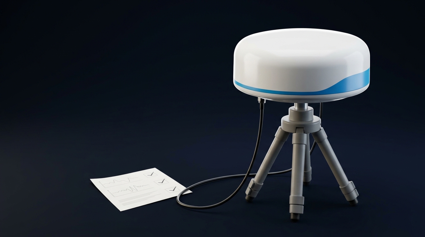
A GNSS antenna doesn’t measure carrier phase at a single, fixed point in space. The effective electrical reception point—the phase center—moves around slightly depending on where the signal comes from.
PCO vs PCV: the distinction that matters
-
PCO (Phase Center Offset) is the average offset of the phase center from the antenna reference point (ARP).
-
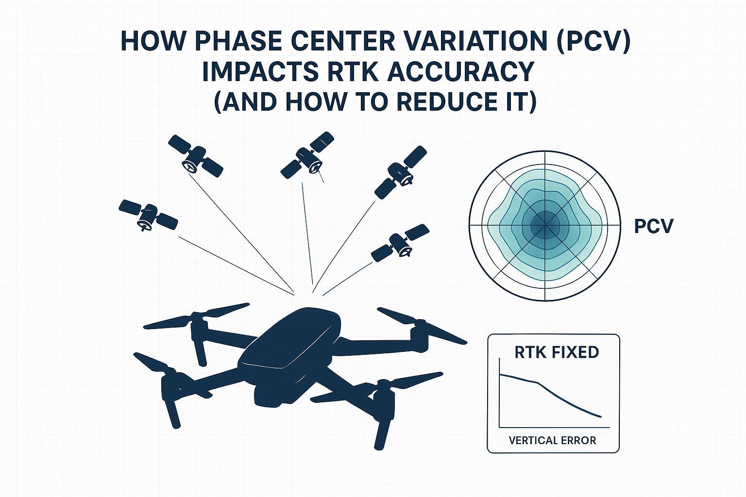
PCV (Phase Center Variation) is the direction-dependent deviation around that mean.
The key detail (that matters for RTK) is that PCV depends on elevation, azimuth, and frequency—it’s a 3D pattern, not a single number. ESA’s explanation of phase center behavior is worth reading if you want the clean definitions and the “don’t mix models” warning in one place (ESA Navipedia: Antenna Phase Centre).
Here’s the mental model I use with teams: PCV is a tiny, angle-dependent error in where your antenna thinks it is. RTK is trying to resolve carrier phase ambiguities at the centimeter level. So even millimeter-scale systematic effects can decide whether you fix fast, fix reliably, and stay fixed.
How PCV turns into RTK error (and why it’s often a vertical problem)
Carrier phase is basically a tape measure with a repeating pattern. RTK works because most errors cancel when you difference observations (base vs rover) and resolve ambiguities. PCV is tricky because it’s not always common-mode:
-
The base and rover may have different antennas, different radomes, different mounts.
-
Even if the antenna model is nominally the same, the near-field environment (ground plane, housing, nearby metal) can change the effective behavior.
-
The satellites you track at low elevation are the ones most likely to light up the ugly parts of the pattern.
When PCV isn’t correctly modeled, you get residual phase biases that leak into the position estimate. In field logs, that can look like:
-
slower TTFF (time to first fix) than you’d expect
-
fix → float transitions when the sky view changes (turns, banking, or simply different satellite geometry)
-
“random” vertical noise that correlates with the elevation distribution of tracked satellites
Why vertical? Geometry. Height is usually the weakest axis in GNSS, and low-elevation satellites (which are important for vertical observability) are also where PCV patterns and multipath sensitivity tend to get nastier.
⚠️ Warning: If your vertical error improves dramatically when you raise the elevation mask from 10° to 20°, you may be hiding a PCV/multipath problem—not solving it.
The UAV-specific amplifier: attitude + airframe + near-field multipath
Most PCV guidance is written for static surveying setups: antenna on a pole, relatively clean environment, long observation windows.
A UAV is the opposite:
-
Attitude changes continuously
-
Even small roll/pitch changes alter which parts of the antenna’s PCV pattern are “sampled” by the sky.
-
If your INS lever arm is tight but your antenna model is wrong, you can still see position bias that looks like lever arm error.
-
-
The near-field environment is complicated
-
Battery, carbon fiber, payload bay shielding, fasteners, coax routing, and even the GNSS module ground can all matter.
-
UNAVCO’s note on site-dependent error sources is a good reminder that what we loosely call “antenna effects” is really a bundle: PCV + far-field multipath + near-field multipath. And near-field multipath can create stable biases that don’t average out—especially in kinematic use (UNAVCO: GNSS antenna sensitivity to site dependent error sources).
-
-
SWaP pushes you toward smaller antennas
-
Smaller, low-profile antennas (especially when the ground plane is compromised) generally have worse pattern control.
-
That doesn’t automatically mean they can’t work—but it raises the bar on calibration and integration discipline.
-
Absolute vs relative antenna models: the fastest way to sabotage a “good” antenna
If you take only one practical point from the theory side, take this:
Don’t mix antenna model conventions.
IGS moved to absolute antenna phase center corrections (distributed as ANTEX), and the ecosystem assumes consistent modeling. That’s what people mean when they say “use an IGS ANTEX antenna model” in a GNSS processing chain.
In an OEM context, “mixing” happens in mundane ways:
-
the base station uses a different antenna model configuration than the rover
-
your PPK toolchain uses ANTEX but your real-time engine doesn’t
-
you change a radome or housing and keep the same antenna definition
The annoying part is that these mistakes don’t always create obviously broken behavior. They create subtle, repeatable biases—the worst kind for mapping.
How PCV shows up in real logs (a scenario I’ve seen more than once)
Let me describe a realistic pattern from a drone mapping integration.
We had a multi-band RTK receiver and a small aviation antenna that looked fine on paper. On open-sky static tests, we could hold FIX and the horizontal looked tight.
But in a mixed environment (light industrial, occasional metallic roofs), the vertical surface would ripple. Not wildly—often a few centimeters—but enough to create seam artifacts.
What finally made it obvious wasn’t the map; it was the correlation with sky view:
-
When the drone turned so that the battery tray and carbon structure sat between the antenna and a cluster of low-elevation satellites, the residuals changed.
-
Fix rate stayed high, but the vertical solution drifted with a period that matched satellite geometry evolution.
The lesson learned was that we were treating PCV as a datasheet number when it’s really a system response. The antenna was part of it, but the mount and near-field environment were doing just as much damage.
Mitigation options ranked by effort vs payoff
If you’re building a drone platform, you usually don’t have time (or budget) for a perfect metrology program on day one. So here’s how I prioritize.
Best practice 1: Start by demanding the right artifacts from your antenna vendor
Why it matters
If you can’t get a credible antenna model (PCO/PCV) or phase center stability characterization, you’re effectively running “best effort RTK.” That’s fine for some drones. It’s not fine for mapping-grade deliverables.
How to implement
Ask for:
-
PCO/PCV data (ideally absolute calibration) for the exact antenna + radome/housing configuration
-
unit-to-unit repeatability or tolerance (type mean vs individual)
-
constraints on ground plane size, mounting, and keep-out region
On the vendor side, what I like to see is that phase behavior is treated as a first-class spec. For example, GNSource’s high-precision product line explicitly calls out phase center stability targets (down to ±1 mm for a reference-style choke ring design, with wider ±2–±5 mm targets for other models), which is at least the right direction for engineering conversations about error budgets (GNSource high-precision GNSS measurement antennas).
Failure mode if you skip this
You end up debugging “RTK instability” at the receiver level when the real culprit is an unmodeled antenna behavior that changes with sky view.
Best practice 2: Treat the ground plane as part of the antenna
Why it matters
On UAVs, the ground plane is usually compromised—too small, cutouts for payload, curved shells, carbon fiber nearby. That directly affects radiation pattern and multipath susceptibility, which in turn changes the effective phase behavior.
This is where the phrase UAV RTK antenna mounting ground plane stops being a checklist item and becomes a design decision you have to lock early.
How to implement
-
If you’re using a patch antenna, build a controlled ground reference into the design: either a dedicated metal plate or a well-defined PCB ground region.
-
Control what’s underneath the antenna. “Open cavity above battery” is a near-field multipath experiment.
-
Don’t assume bigger is always better—validate.
A useful data point: a 2023 study on RTK-GNSS antennas and supplementary ground planes found that a ∅15 cm circular aluminum ground plane often outperformed a larger 30×30 cm plate for certain setups, while also being more UAV-practical. The key takeaway is that shape/size is antenna-dependent, and the impact shows strongly in vertical stability (Copernicus ARS 2023 ground plane study).
Failure mode if you skip this
You can get a drone that passes open-sky demos and fails when you fly near reflective surfaces or rotate through different azimuths.
Best practice 3: Choose your calibration level intentionally
Why it matters
There’s a big difference between:
-
“We need consistent 2–5 cm mapping outputs across fleets and environments”
-
“We just need RTK for better navigation”
The first case often justifies deeper work: better antennas, more controlled mounting, stronger modeling.
How to implement
I frame it as three tiers:
-
Tier A (fast, pragmatic)
-
pick an antenna with published GNSS antenna phase center stability behavior and integration guidance
-
enforce a repeatable mount + ground plane
-
gate acceptance on logs/metrics (more on that below)
-
-
Tier B (engineering discipline)
-
keep antenna model conventions consistent across RTK and PPK
-
standardize antenna + radome config across production
-
-
Tier C (metrology-grade)
-
absolute GNSS antenna calibration (individual or batch characterization)
-
tight mechanical tolerances and assembly QA
-
Failure mode if you skip this decision
You end up with a half-built Tier C program (cost without closure), and you still ship a product with Tier A performance.
Best practice 4: Separate PCV problems from correction-link problems with simple A/B tests
Why it matters
Correction link dropouts, latency, and ionosphere can create symptoms that look like antenna issues. You need a test that isolates variables.
How to implement
A pattern that works:
-
run a static test on a known point (or local benchmark) with stable corrections
-
repeat with only one variable changed:
-
antenna model/configuration
-
mount + ground plane
-
antenna placement on the airframe
-
If the error signature changes with those variables while corrections remain stable, you’re likely dealing with antenna/PCV/multipath coupling.
Failure mode if you skip this
You burn weeks on firmware tuning, but your vertical wander survives every software change.
Best practice 5: Learn the PCV “fingerprints” in telemetry
Why it matters
If you can’t detect the problem, you can’t control it at production scale.
How to implement
In logs, look for:
-
correlation of residuals with satellite elevation bins
-
correlation with heading/azimuth (especially after yaw maneuvers)
-
vertical error spikes that line up with low-elevation satellite dominance
-
fix transitions when attitude changes quickly
This isn’t about blaming PCV for everything—it’s about having a hypothesis that matches the physics.
A practical evaluation framework: which mitigation should you pick?
When an engineering lead asks me “what do we do?” I push it into a decision table. Not because tables are pretty—but because they force trade-offs into the open.
Mitigation | Effort | Risk reduction | When it’s the right move | Hidden gotcha |
|---|---|---|---|---|
Better antenna with proven phase behavior | Medium | High | mapping-grade deliverables, fleet consistency | can still fail if mount/ground plane is sloppy |
Controlled ground plane + keep-out region | Medium | High | SWaP allows a defined metal/PCB region | late mechanical changes break it |
Consistent antenna models across toolchain | Low–Medium | Medium–High | you use RTK + PPK and need consistent results | model availability for your exact antenna+radome |
Individual calibration program | High | Very high | high-volume fleet, tight vertical requirements | cost, lead time, process maturity |
Elevation mask / weighting tweaks | Low | Low–Medium | band-aid to reduce worst low-elevation behavior | can reduce availability and hide integration flaws |
Where GNSource fits (without turning this into a brochure)
If you’re evaluating antenna suppliers, the most useful filter isn’t “who has the highest gain.” It’s “who can give us the artifacts to model and validate phase behavior.”
For a starting point on the product side, GNSource’s aviation category shows typical airborne form factors and environmental constraints (GNSource aviation & UAV antennas). If you want to browse their broader portfolio by application, start at the main catalog and then narrow down by your platform constraints (GNSource product catalog).
Closing: the simplest way to reduce PCV risk this quarter
If I had to boil this down to a pragmatic sequence:
-
Choose an antenna with credible phase center stability characterization.
-
Lock a repeatable mount + ground plane early in mechanical design.
-
Keep antenna model conventions consistent across RTK and PPK.
-
Validate with A/B tests that isolate antenna + mount variables.
If you’re integrating a new airframe and want a sanity check on your constraints (bands, SWaP, mounting geometry, and what calibration files your toolchain needs), start a technical inquiry and request the phase center artifacts up front (GNSource custom engineering inquiry).