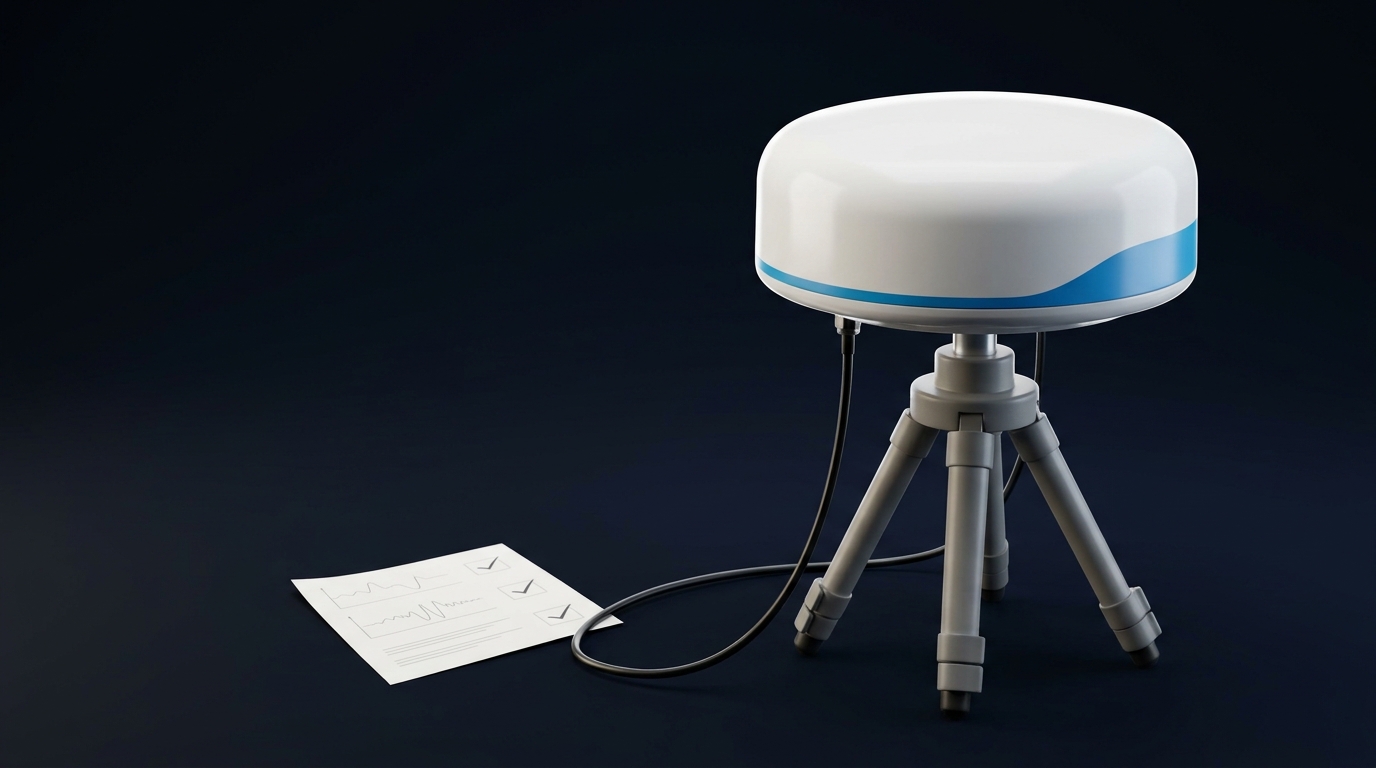
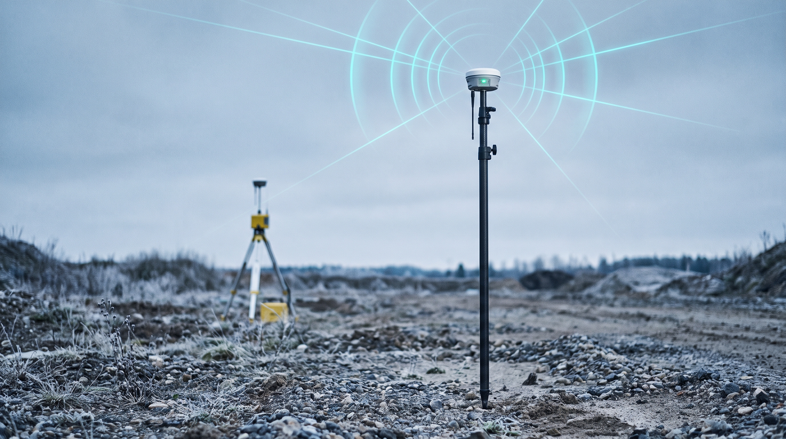
![How to Set Up an RTK Base Station Antenna [2026 Guide]](/blog/_assets/upload/aaacdd5rjxygrxhc/2026/06/17/image_1781704508-i4v1t4p5.jpeg)
An RTK base station antenna is the single most hardware-dependent element in a Real-Time Kinematic (RTK) positioning chain. Get the antenna installation wrong — poor sky view, unstable mount, inadequate cabling — and no amount of receiver calibration or software tuning will recover the lost accuracy.
This guide covers the complete setup process for RF timing engineers and site deployment teams: from site selection through antenna mounting, cabling, coordinate establishment, and commissioning validation. It assumes you already know what RTK does and why you need it—and that you’ve already picked a suitable antenna, which our guide to choosing a high-precision GNSS antenna covers.
Before You Begin: What You’ll Need
-
GNSS antenna: Survey-grade or geodetic multi-band antenna (L1/L2/L5 minimum). A choke-ring or large-ground-plane design is strongly preferred for base station duty.
-
Receiver: An RTK-capable receiver that supports base station mode (outputting RTCM 3.x correction messages).
-
Mounting hardware: Rigid pole mount, tripod, or rooftop bracket rated for permanent outdoor installation.
-
RF cabling: Low-loss coaxial cable (LMR-400 or equivalent), pre-terminated when possible.
-
Surge protector: Inline coaxial lightning arrestor rated for GNSS frequencies.
-
Power and connectivity: Stable power source (PoE or DC), Ethernet or cellular backhaul for NTRIP distribution.
Pro Tip: Always connect the antenna to the receiver before applying power. Powering a receiver without an antenna connected can damage the LNA input stage.
Step 1: RTK Base Station Antenna Site Selection
Site selection is the highest-leverage decision in any RTK base station antenna installation. A perfectly mounted antenna at a bad location will underperform a mediocre antenna at a great location.
Sky Visibility Requirements
The antenna needs an unobstructed view of the sky from 10° elevation upward. Walk the candidate site and check for:
-
Buildings and structures: Any blockage above 10° elevation will reduce satellite visibility and introduce diffraction effects.
-
Tree canopy: Seasonal growth can turn a marginal site into a failed one. Survey during full-leaf conditions.
-
Rooftop equipment: HVAC units, satellite dishes, and other rooftop structures create both blockage and multipath risk. Maintain at least 3 meters of horizontal separation.
Multipath Risk Assessment
Multipath — reflected GNSS signals arriving at the antenna out of phase with the direct signal — is the leading environmental cause of RTK accuracy degradation at the base station.
According to Canada’s GNSS reference station installation guidelines, reflective surfaces within approximately 30 meters should be flagged as multipath hazards:
-
Metal fences and walls
-
Vehicle parking areas
-
Sheet-metal roofs and HVAC ducting
-
Large glass facades
-
Nearby towers and guy wires
RF Interference Survey
Before finalizing the site, assess the RF environment:
-
Keep at least 10 meters from other transmitting antennas (cellular panels, microwave links, Wi-Fi access points)
-
Avoid locations directly beneath high-voltage power lines
-
Note any radar installations within line of sight
-
Check for known jamming or spoofing sources in dense urban environments
GNSource’s guide on GNSS multipath mitigation for geodetic reference stations provides a practical framework for antenna selection and placement that directly addresses these environmental factors.
Step 2: Antenna Mounting
Once the site passes the selection criteria, the mounting itself must preserve everything the site provides.
Mount Selection
Mount Type | Best For | Considerations |
|---|---|---|
Roof-penetrating bracket | Permanent installations | Requires waterproof flashing; strongest mechanical bond |
Non-penetrating roof mount | Leased rooftops, flat roofs | Ballasted; verify wind load rating for your region |
Wall-mount bracket | Building facades, lower cost | Limited sky view on one side; verify clear elevation |
Tripod / temporary pole | Field deployments, surveys | Must be guyed for wind stability; not suitable for permanent timing installations |
Ground Plane
A ground plane suppresses multipath from below the antenna and improves low-elevation satellite tracking. Most survey-grade geodetic antennas include an integrated ground plane (typically 20–40 cm diameter). If your antenna does not include one, mount the antenna on a flat metallic surface at least 20 cm in each dimension, as recommended in the ArduSimple RTK base station guide.
Leveling and Orientation
-
The antenna must be level within 0.5° in all directions. Tilt causes asymmetric phase-center variation that directly degrades RTK accuracy.
-
For antennas with a visible orientation mark (e.g., north arrow), align the antenna to true north. This ensures the phase-center offset vector is applied correctly in post-processing.
-
Torque the mounting bolts to the manufacturer’s specification. Under-torqued mounts drift over time; over-torqued mounts can deform the antenna housing.
Structural Stability
The antenna must not move under any expected environmental load. Trimble’s base station operation guidelines emphasize that even sub-millimeter antenna movement introduces RTK errors that cannot be corrected at the rover.
Checklist for structural verification:
-
Mount attached to the building’s primary structure, not to roofing material or fascia
-
All fasteners are stainless steel for corrosion resistance
-
Mount rated for the maximum expected wind speed at the site (typically 120–160 km/h for permanent installations)
-
No perceptible movement when 5 kg lateral force is applied at the antenna mounting point
For permanent installations, GNSource’s high-precision GNSS survey and RTK antenna line includes models specifically designed for CORS and permanent reference station deployments, with integrated ground planes and ruggedized housings that simplify the mounting decision.
Step 3: Cabling and Surge Protection
Cabling is the most common source of field failures in permanent RTK installations. The antenna may be perfectly placed, but a damaged or poorly installed cable will introduce noise, signal loss, and eventual receiver damage.
Cable Selection
-
Type: Low-loss 50 Ω coax — LMR-400, Belden 9913, or equivalent. Avoid RG-58 or RG-174 for runs longer than 5 meters.
-
Length: Keep the run as short as practical. GNSS signals at L-band frequencies are sensitive to cable attenuation; a 30-meter run of LMR-400 loses approximately 3–4 dB at 1.5 GHz.
-
Pre-terminated vs. field-terminated: Pre-terminated cables with factory-installed connectors are strongly preferred. Field-terminated connectors are the most common point of water ingress and impedance mismatch.
-
Connector type: TNC or N-type connectors for permanent outdoor installations. SMA connectors are acceptable for short indoor jumper runs only.
Lightning and Surge Protection
Outdoor GNSS antenna installation guidance from Safran specifies that a surge suppressor is strongly recommended for permanent outdoor installations.
Installation sequence:
-
Place the lightning arrestor inline on the antenna coax at the point where the cable enters the building
-
Bond the arrestor body to the building’s earth ground using the shortest practical conductor (less than 1 meter ideal)
-
Verify the arrestor’s frequency rating covers your GNSS bands (typically 1.1–1.6 GHz)
-
Do NOT ground the antenna mount to the arrestor ground path — use a separate ground rod for the antenna structure when required by local code
Cable Routing
-
Avoid sharp bends — minimum bend radius for LMR-400 is approximately 25 mm
-
Use cable clips or tray supports every 1 meter for horizontal runs
-
Drip loops at both entry and exit points to direct water away from connectors
-
UV-resistant cable jacket for any exposed outdoor sections
⚠️ Warning: GNSS timing antennas for 5G TDD base stations require special care: if the cable run exceeds 20 meters, verify that the LNA gain (typically 28–40 dB at the antenna) plus any inline amplification still provides adequate signal-to-noise ratio at the receiver input, considering total cable loss. Insufficient SNR at the timing receiver may degrade PTP holdover performance.
Step 4: Coordinate Setup
The base station’s known position is the anchor for every rover correction. An inaccurate base coordinate means every rover position inherits that error.
Method Selection
Method | Absolute Accuracy | Effort | Best For |
|---|---|---|---|
Known survey benchmark | Best available | Low (if available) | Permanent installations on surveyed sites |
Static post-processing (PPP) | 1–3 cm | High (24h+ observation) | New permanent sites without existing benchmarks |
Survey-in (averaging) | 1–2 m absolute, cm relative | Low | Temporary setups, field surveys |
Manual coordinate entry | Depends on source quality | Minimal | When coordinates are already certified |
As detailed in Emlid’s guide to setting up a GNSS base for centimeter accuracy, the survey-in method is acceptable for relative positioning but should not be relied upon for absolute accuracy if the base station will serve as a permanent timing reference.
For 5G timing applications where the base station may be part of a PRTC (Primary Reference Time Clock) chain, static post-processing or a known benchmark is the minimum standard. The absolute position accuracy directly affects the timing reference calibration.
Antenna Height Measurement
Measure and document the antenna height from the ground marker to the antenna reference point (ARP) — typically the base of the antenna mounting threads. Record:
-
Measured height (to 1 mm)
-
Date of measurement
-
Who performed the measurement
-
Method used (taped height vs. leveled rod)
Step 5: Validation and Commissioning
Before the installation goes live, run through this commissioning checklist:
Pre-Power Checks
-
Antenna connected to receiver before power-on
-
All connectors hand-tightened (no tools on SMA)
-
Cable routing confirmed — no sharp bends, no kinks
-
Surge arrestor grounded
-
Mount verified level and rigid
Power-On Checks
-
Receiver powers on and acquires satellites within 2 minutes
-
Minimum 6 satellites tracked on each of L1 and L2 bands
-
C/N0 (carrier-to-noise density) above 40 dB-Hz for tracked satellites
-
Survey-in completes within configured accuracy threshold
-
RTCM message output confirmed on the configured port
Stabilization Check
-
Base station runs for minimum 1 hour with no unexpected resets
-
Coordinate solution stabilizes (less than 2 cm drift in the last 30 minutes)
-
No satellite dropouts observed during the stabilization period
-
Rover obtains RTK FIX at known test point within 60 seconds
Log the stabilization data to the receiver’s onboard storage or an external file. This baseline is essential for future troubleshooting.
Special Considerations for 5G Timing Deployments
When the RTK base station antenna serves a 5G TDD timing function (GNSS-disciplined PRTC/ePRTC), several additional requirements apply:
ITU-T Compliance
The installation must support compliance with ITU-T G.827x timing standards, including:
-
G.8271: Phase/time synchronization limits for TDD — requires end-to-end time error within ±1.5 µs
-
G.8273: Timing characteristics of PRTC equipment
-
G.8275.1 / G.8275.2: Full-timing and partial-timing support profiles for PTP
These standards specify the allowable time error contributions from each element in the synchronization chain. The GNSS antenna installation’s contribution to time error (cable delay asymmetry, multipath-induced jitter, position error) must be quantified and tracked.
Anti-Jam Resilience
For urban and industrial 5G deployments, antenna placement must consider GNSS jamming and spoofing threats:
-
Position the antenna away from public access areas where personal jammer devices are commonly used (parking lots, building entrances)
-
Consider GNSource’s GNSS timing antenna line for deployments requiring enhanced resilience — these antennas include 1 kV lightning protection, 36 dB LNA, and IP67-rated enclosures designed for continuous outdoor timing operation
-
For high-risk sites (critical infrastructure, financial networks), evaluate adaptive CRPA (Controlled Reception Pattern Antenna) solutions that can null interference sources
Holdover Considerations
During GNSS signal outages, the base station’s oscillator holds the timing reference. A clean, interference-free GNSS signal during normal operation is essential for accurate oscillator disciplining. Cable and antenna issues that degrade C/N0 by even 3–5 dB-Hz can measurably shorten the achievable holdover window. Validate the installation with at least 48 hours of continuous operation before certifying holdover performance.
Common Mistakes to Avoid
Mistake | Consequence | Fix |
|---|---|---|
Mounting near reflective surfaces | Multipath-induced RTK errors that cannot be averaged out | Survey the site with a compass and inclinometer before mounting |
Using a patch antenna for the base station | Poor multipath rejection, degraded low-elevation tracking | Use a survey-grade geodetic antenna with ground plane |
Overtightening SMA connectors | Permanent connector damage, impedance mismatch | Hand-tighten only (0.5–0.8 N·m) |
Long cable runs with RG-58 | 6–10 dB loss, insufficient SNR at receiver | Use LMR-400 or better; verify link budget |
Skipping surge protection | Receiver damage from lightning-induced surges | Install inline arrestor at building entry |
Relying on survey-in only for absolute position | 1–2 m absolute error in all rover positions | Post-process 24 hours of data through PPP |
Not documenting the antenna height | Future maintenance teams can't verify installation correctness | Log height, date, and measurement method |
Mounting without verifying structural stability | Time-dependent position drift that is nearly impossible to troubleshoot | Apply lateral load test during commissioning |
Next Steps
A properly installed RTK base station antenna, combined with a standards-compliant receiver and stable correction distribution, will deliver reliable centimeter-level positioning and nanosecond-level timing for years.
For deployment-specific guidance — whether you need an antenna for a rooftop 5G timing site, a permanent CORS reference station, or a field-deployable RTK base — share your requirements with the GNSource engineering team. The right antenna selection depends on your signal environment, cable run length, frequency plan, and mechanical constraints, and discussing those details directly is the most efficient path to a successful installation.