A high-precision GNSS installation lives or dies by its antenna. You can pair a $30,000 multi-frequency receiver with a $200 patch and watch your RTK solution drift by 14 mm in open sky and 30 cm in an urban canyon. Pair the same receiver with a properly calibrated geodetic antenna and you’ll see horizontal accuracy under 6 mm — a 2× to 3× improvement that comes entirely from one component upstream of the cable. Peer-reviewed studies in GPS Solutions (Hamza et al., 2024) report geodetic-grade antennas deliver consistently two to three times the horizontal accuracy of low-cost rover patches under open-sky conditions, with the gap widening sharply once buildings, water, or vehicles enter the scene.
This guide is for engineers who have to write an RFP, sign off on a hardware spec, or defend their selection in front of a procurement committee. It’s organised around the workflow you actually do — RTK rover, CORS base station, machine control, precision agriculture, UAV integration — rather than a list of vendor part numbers. By the end you’ll have an 8-item checklist you can paste into an RFQ and a clear answer to the question every engineer eventually faces: do I really need a choke-ring, or will an integrated geodetic do?
The high-precision GNSS antenna market reached USD 1.39 billion in 2025 and is forecast to grow at a 6.4% CAGR through 2033 (Valuates Reports). The wider GNSS downstream market — receivers, services, integrated solutions — was valued at €260 billion in 2023 and is projected to reach €580 billion by 2033 (EUSPA EO and GNSS Market Report 2024). The point: there is no shortage of vendors trying to sell you an antenna. Knowing how to filter their datasheets is now table stakes.
TL;DR — 60-second decision matrix
If you only read one section, read this.
Your workflow | Antenna class | Why |
|---|---|---|
CORS / IGS-grade base station | Calibrated choke-ring | Sub-mm phase center; multipath suppression critical for absolute reference |
Cadastral / boundary survey | Integrated geodetic, multi-band | Sub-cm horizontal with RTK; portable; calibrated PCV |
Machine control (excavators, dozers) | Ruggedised geodetic patch, multi-band | Vibration-tolerant; low-profile; integrated heater |
Precision agriculture (1–3 cm) | Multi-band rover antenna | Cost-conscious; wide aperture; multi-constellation |
UAV / mobile mapping | Compact multi-band (L1+L5 minimum) | Lightweight; needs L5 for ionospheric correction at altitude |
Static geodesy / deformation monitoring | Choke-ring + D&M element, calibrated | Long-term mm-stable repeatability over years |
8-item RFQ checklist (expanded later in the article):
-
Supported signals — list every band you plan to track, by constellation
-
Phase center calibration availability — IGS
igs20.atxor NGS ANTCAL -
Phase center variation (PCV) — peak-to-peak in mm at L1 and L5
-
Axial ratio at boresight and at 10° elevation
-
LNA noise figure and gain (separately stated, not lumped)
-
Out-of-band rejection and saturation power
-
Operating temperature and IP rating
-
Mechanical reference point and tape-measure offset
1. Start with the workflow, not the spec sheet
Most antenna selection mistakes happen because the buyer starts on page 2 of a datasheet instead of page 1 of their own project brief. Every meaningful trade-off in a GNSS antenna — phase center stability vs. weight, multipath rejection vs. low-elevation gain, choke-ring depth vs. aperture diameter — only makes sense against a specific positioning workflow.
Four workflows dominate high-precision use:
Real-time kinematic (RTK) uses carrier-phase measurements from a known base station to give a rover centimetre-level horizontal accuracy in real time — typically 1–3 cm with a fixed integer ambiguity solution. The antenna’s job is to deliver clean carrier-phase observations to the receiver, which means low multipath, stable phase center, and good axial ratio across the upper hemisphere.
Precise Point Positioning (PPP) uses precise satellite ephemeris and clock corrections — typically from IGS or a commercial service — to compute a global solution without a local base. Convergence times of 10–30 minutes are common. PPP demands the same phase-center quality as RTK plus excellent group-delay stability across the bands used in the ionosphere-free combination.
CORS reference stations are the absolute reference everyone else’s RTK or PPP solution depends on. A CORS antenna sits in one place for years and must hold a sub-millimetre phase center across temperature, humidity, and ageing. This is the only workflow where a true choke-ring is genuinely non-negotiable.
Static post-processing for geodetic surveying, deformation monitoring, and crustal motion studies pushes accuracy to the sub-millimetre level over baselines of hundreds of kilometres. Like CORS, it depends on absolutely stable phase centers and well-characterised group delay.
If your workflow is rover RTK in a vineyard, you don’t need a choke-ring — and putting one on a UAV would be absurd. If you’re building a CORS station for a regional network, a “rugged multi-band geodetic antenna” without an IGS calibration will quietly destabilise every solution that base computes. The workflow determines the antenna class; the spec sheet only validates the choice within that class.
The accuracy hierarchy across antenna classes — under open sky, with the same receiver and processing — looks roughly like this:
Antenna class | Typical horizontal RTK accuracy | Typical vertical RTK accuracy |
|---|---|---|
Consumer / smartphone patch | 1–3 m (no RTK) | 3–10 m |
Low-cost dual-frequency patch | 10–20 mm | 30–60 mm |
Integrated geodetic, multi-band | 5–8 mm | 10–15 mm |
Choke-ring with D&M element | 3–6 mm | 8–12 mm |
These are open-sky numbers from peer-reviewed comparisons (Hamza et al., 2024; MDPI Sensors 2023, PMC10007599). In a multipath-rich environment the gap between the bottom and top of this table widens by a factor of two to five, because cheap antennas have nothing to suppress reflected signals while choke-rings actively reject them.
2. Multi-constellation, multi-frequency — non-negotiable in 2026
Six operational global or regional navigation systems are now in service, and a modern survey antenna receives all of them. Selecting an antenna that supports only a subset is throwing away satellite visibility, DOP, and ambiguity-resolution speed. Vendor “L1/L2 GPS” antennas still appear on tender lists, and engineers still accidentally specify them. Don’t.
The bands an actual high-precision antenna covers
Constellation | Bands a modern multi-band antenna should cover | Center frequency (MHz) |
|---|---|---|
GPS | L1, L2, L5 | 1575.42, 1227.60, 1176.45 |
GLONASS | G1, G2, G3 | 1602.0, 1246.0, 1202.025 |
Galileo | E1, E5a, E5b, E5, E6 | 1575.42, 1176.45, 1207.14, 1191.795, 1278.75 |
BeiDou | B1I, B1C, B2a, B2b, B3I | 1561.098, 1575.42, 1176.45, 1207.14, 1268.52 |
QZSS | L1, L2, L5, L6 | 1575.42, 1227.60, 1176.45, 1278.75 |
NavIC | L5 | 1176.45 |
Frequencies above are taken directly from the published Interface Control Documents (IS-GPS-200/705 from gps.gov; the Galileo OS SIS ICD v2.1; the BeiDou ICD v3.0; the QZSS Service Definition; ESA Navipedia for GLONASS and NavIC). Notice how many constellations share a band — L1 at 1575.42 MHz, L5/E5a/B2a at 1176.45 MHz — which means a well-designed antenna covering “L1 + L5” actually gets simultaneous use of GPS L1, Galileo E1, BeiDou B1C and GPS L5, Galileo E5a, BeiDou B2a, QZSS L5, NavIC L5 — easily 30+ satellites in view from a single mid-latitude site.
For a deeper reference, see our GNSS frequency bands tool — it visualises every published civil signal across the L-band so you can map your antenna’s spec against actual available signals.
Why L1+L5 beats L1+L2 for high-precision work
For decades, “L1+L2” was the dual-frequency convention for geodetic GNSS. The argument for switching to L1+L5 as your primary ionosphere-free combination is well established and worth understanding:
-
Wider frequency separation reduces ionospheric estimator variance. L1 to L5 spans 398.97 MHz versus 347.82 MHz from L1 to L2. The wider gap gives a more sensitive observation of the ionospheric delay, which scales as 1/f².
-
L5 sits in an ARNS-protected band. The 1164–1215 MHz allocation is reserved by the ITU for Aeronautical Radio Navigation Services — protection that L2 (1215–1239 MHz, 1240–1300 MHz portions) doesn’t enjoy. In jamming-prone or RFI-heavy environments, L5 is materially cleaner.
-
Lower observation noise on L5. Modern signals like GPS L5 and Galileo E5a use a 10.23 MHz chipping rate versus 1.023 MHz for GPS L1 C/A and 511.5 kHz for GPS L2C’s data channel. Higher chipping rate means narrower correlation peaks and lower pseudorange noise — the Wübbena and Yi papers in Journal of Geodesy quantify this carefully.
If you can only afford a dual-frequency antenna, choose one that includes L5 — not L2. If your receiver is L1+L2 only, you’ll get a usable antenna by buying triple-frequency anyway; the marginal cost is small and the future-proofing is real.
3. Phase center stability — the single most important spec
Every other spec in this article matters less than this one. The phase center of an antenna is the conceptual point in space from which the antenna appears to radiate or receive — the reference point all your subsequent geodetic computations assume. It is not a fixed mechanical location. It shifts with the angle of arrival of the incoming signal (this is the phase center variation, PCV) and with frequency (the L1 and L5 phase centers of the same antenna are different points).
For a survey rover producing a 2 cm RTK fix, a 2 mm PCV is a measurable fraction of your accuracy budget. For a CORS station whose coordinates anchor every other observation in a regional network, a 1 mm phase center drift cascades through every dependent solution. This is why the IGS, the NGS, and every national geodetic agency maintain calibration files that publish the measured phase center offset and variation for every antenna model they accept.
The numbers that matter
-
Uncalibrated geodetic antennas typically show 2–5 mm PCV at L1 across the upper hemisphere, with worst-case excursions up to 6 mm reported in robot-vs-chamber comparisons (Riddell et al., GPS Solutions 2020).
-
Calibrated choke-rings typically maintain <1 mm PCV at L1 across the same elevation range (UNAVCO antenna calibration notes).
-
The same antenna can show 3× larger PCV at L5 than at L1 simply because the wavelength is 33% longer and the element geometry was tuned for L1.
-
Group-delay variation across band is a separate but related issue: peer-reviewed measurements show 0.3–0.4 m peak-to-peak GDV on the satellite side at L1/L5 (Wübbena et al., Journal of Geodesy 2017), with receiver-side antenna contributions typically smaller but not always negligible.
The choke-ring + D&M element — why it’s still the reference
The choke-ring geometry was first published for high-precision GPS use by Tranquilla and Colpitts in 1989 (ASCE Journal of Surveying Engineering 115:1, 2–14), pairing a JPL-designed Dorne-Margolin (D&M) crossed-dipole element with a set of concentric quarter-wave-deep choke rings. The depth of the rings is set by the wavelength: at L1 (190.3 mm), a quarter-wave ring is ~47.6 mm; at L2 (244.2 mm), ~61.1 mm. The rings present a high impedance to surface currents arriving from low elevation angles, suppressing the back-lobe response and dramatically reducing multipath pickup from the ground. The element + choke combination has been the de-facto reference geometry for the IGS analysis-centre network for over three decades.
For broader-band coverage (Galileo E6 at 1278 MHz, BeiDou B3I at 1268 MHz, the upper L-band correction services), modern designs use dual-depth or convoluted choke geometries to maintain a stable rejection profile across a wider range of wavelengths. These cost more but extend the calibrated band coverage.
Check the calibration file before you buy
This is the single most concrete pre-purchase test you can run, and most engineers skip it:
-
Download the current IGS ANTEX file
igs20.atxfrom https://files.igs.org/pub/station/general/igs20.atx -
Search for the antenna model name (the standardised 16-character IGS identifier — e.g.
TRM57971.00for the Trimble Zephyr 2) -
Confirm the file contains PCV entries for every frequency your workflow uses
-
Cross-check against the NGS ANTCAL portal at https://geodesy.noaa.gov/ANTCAL/ for an independent calibration
If a vendor’s “geodetic” antenna isn’t in the IGS or NGS calibration files, the model has not been through the standard relative-calibration process — meaning you can’t compute corrected positions without commissioning a calibration yourself, which costs thousands and takes weeks. This filter alone rules out a surprising number of products in the $500–$2,000 range that market themselves as “survey-grade.”
4. Multipath rejection — the second most important spec
Multipath — the arrival of GNSS signals reflected from buildings, water, vehicles, or the ground in addition to the direct line-of-sight — is the single largest error source for unmitigated high-precision GNSS work in real environments. The direct signal travels in a straight line from satellite to antenna; the reflected signal takes a longer path, arrives microseconds later, and adds a phase-shifted copy of the same code and carrier. Receivers do their best to discriminate, but the dominant tool for fighting multipath is the antenna itself.
Two physical mechanisms suppress multipath at the antenna:
Geometric rejection — the antenna is designed to be insensitive to signals arriving from below the horizontal plane. Choke-ring designs are the canonical implementation. Peer-reviewed measurements show modern choke-rings deliver a front-to-back ratio above 22 dB, with ranging-grade designs reaching >40 dB (Lin et al., IJAP 2022). A patch antenna on a small ground plane typically achieves 10–15 dB.
Polarisation rejection — direct GNSS signals are right-hand circularly polarised (RHCP). After a single ground reflection, the polarisation flips to left-hand (LHCP). A well-designed RHCP antenna intentionally has poor sensitivity to LHCP signals — and the metric that quantifies this is the axial ratio. A perfect RHCP antenna has an axial ratio of 0 dB; real antennas have <3 dB at boresight and 3–6 dB at low elevations. The lower the axial ratio, the more aggressively the antenna rejects reflected LHCP signals.
The relationship between axial ratio and cross-polarisation discrimination is direct:
Axial ratio | Cross-pol discrimination (LHCP rejection) |
|---|---|
1 dB | ~25 dB |
3 dB | ~15 dB |
6 dB | ~9 dB |
The GPS World “Innovation” column (an engineering-reviewed series) reports that improving boresight axial ratio from 3 dB to 1 dB can yield 20+ dB of additional multipath suppression, which translates to centimetre-level position improvements in static baselines. A choke-ring antenna typically holds axial ratio under 3 dB across the entire upper hemisphere — not just at boresight — which is why it remains the reference. Tallysman’s VeraPhase 6000 publishes <0.5 dB axial ratio at zenith and <2 dB at horizon, demonstrating that aggressive AR control is achievable in modern designs.
For a comparative measurement in independent literature, choke-rings deliver direct-to-multipath ratios of 10–23 dB at low elevation (5°) versus 4–14 dB for patch antennas on standard ground planes (Lin, International Journal of Antennas and Propagation 2022). The dB difference compounds: a 10 dB improvement in multipath rejection translates roughly to a 3× reduction in pseudorange multipath noise and a comparable improvement in carrier-phase variance.
If you want to see the geometry visually, the multipath glossary entry on our site includes an interactive widget that plots direct + reflected signal interference for a tunable extra path length — useful for explaining the problem to non-RF colleagues.
5. Gain pattern, the LNA chain, and the active-antenna myth
This is where vendor marketing language and engineering reality diverge most sharply. You will see specs like “50 dB antenna gain” on glossy product pages. Treated naïvely, that number is nonsense — no RF element radiates 50 dB above isotropic. What’s actually being quoted is the combined gain of the antenna element and the integrated low-noise amplifier (LNA), which is a chain gain figure, not an antenna gain figure. The antenna element itself contributes typically 3–5 dBic of gain at zenith for a multi-band geodetic element. The LNA contributes the remaining 35–45 dB of chain gain.
What you actually need to know
For a high-precision design, three numbers about the active-antenna chain matter:
-
Element gain at zenith and at 10° elevation. A well-designed multi-band element should hold ~3 dBic at zenith and drop by no more than 7–8 dB at 10° elevation. Bigger drop = worse low-elevation satellite reception = fewer satellites available for RTK ambiguity resolution.
-
LNA noise figure (NF). This sets the floor for your C/N₀. A modern survey-grade LNA should publish NF < 2.0 dB, ideally <1.8 dB. Higher NF means worse signal-to-noise on every observation. Tallysman’s VeroStar publishes 1.8 dB NF as a design target; this is the right ballpark.
-
Cascade gain and saturation behaviour. The LNA gain has to overcome cable loss to the receiver. At L-band, RG-58 has roughly 1 dB/m attenuation; LMR-400 about 0.18 dB/m. A 30 m run of RG-58 chews 30 dB — so a 35 dB LNA gives the receiver effectively 5 dB of headroom, which is marginal. Use our Link Budget Calculator to size the LNA gain against your specific cable and receiver requirements.
The mistake everyone makes the first time
C/N₀ does not scale with chain gain. Adding more LNA gain amplifies signal and noise equally — what determines your final C/N₀ is the noise figure of the first stage in the chain. This is why a “50 dB” antenna with NF 3.5 dB will produce worse survey results than a “35 dB” antenna with NF 1.5 dB on the same satellite. Don’t shop for gain. Shop for noise figure, and let gain be whatever is needed to overcome the cable.
Other LNA chain specs that bite
-
Out-of-band rejection. Modern cellular bands (LTE Band 13 at 746–787 MHz, LTE Band 14 at 758–798 MHz) and ISM 2.4 GHz can saturate an LNA if it doesn’t have aggressive front-end filtering. Look for “out-of-band rejection > 40 dB at LTE bands” as a specified figure.
-
Saturation input power. Most survey-grade LNAs saturate around -30 dBm input. If you’re operating near a high-power transmitter (radar, broadcast tower, base station), this matters.
-
DC bias requirements. Active antennas need DC power delivered up the coax via a bias-tee — typically 3.3 V to 12 V at 30–100 mA. Confirm your receiver supplies the correct voltage and current.
6. Eight mistakes engineers actually make
Surveyor forums (RPLS Today, GeoNet) and vendor field notes (Emlid, Harxon) converge on a consistent set of antenna-related failure modes. Knowing them in advance is the cheapest insurance you’ll buy.
1. Buying a GPS-only antenna with a multi-constellation receiver. Limits your visible-satellite count to roughly 40% of what a multi-constellation receiver can actually track. In open sky you’ll still get a fix; in canyons, under canopy, or near walls you’ll lose ambiguity resolution far more often than necessary.
2. Reading “50 dB gain” as element gain. Covered in §5 — this is the chain gain figure, not the element gain. Decisions made on this number alone lead to overspending on the wrong attribute.
3. Skipping the ANTEX calibration check. An antenna without an entry in igs20.atx or NGS ANTCAL cannot have its phase center corrections applied in standard processing software (BERNESE, GAMIT, RTKLIB, Trimble Business Centre, Leica Infinity). You’ll either compute uncorrected positions or commission your own calibration — at significant cost.
4. Miscalculating antenna height to the wrong reference point. Every antenna manufacturer publishes a mechanical reference point (MRP) — the location on the antenna case from which all height measurements should be made to the phase center. This is not always the bottom of the radome, and it varies by model. Emlid’s surveying-mistakes post calls this out as one of the most common field errors. Always confirm the MRP-to-phase-center offset in the calibration file, not just the datasheet.
5. Putting a patch antenna directly on a tripod without a ground plane. Patch antennas are designed to work with a ground plane below them — typically a 100 mm or larger metallic disk. Skip the ground plane and the rear-hemisphere pattern degrades dramatically, often pulling in 15–20 dB more multipath than the antenna would otherwise reject.
6. Cable-length mismatch — under-gained or saturated chain. Pairing a low-gain LNA with a long run, or a high-gain LNA with a short run + low-NF receiver, produces either marginal C/N₀ or saturation distortion. Use the Link Budget Calculator before ordering.
7. Ignoring axial ratio at low elevation. Datasheets often quote axial ratio “at boresight” only. The vendor that publishes AR at 0°, 10°, 30°, 60°, and 90° elevation is signalling design discipline; the one that quotes only zenith is hiding something. Multipath is dominated by signals arriving from low elevations — exactly where axial ratio degrades worst.
8. Underestimating thermal and mechanical environment. A geodetic antenna on a CORS mast experiences -40 °C in winter, +60 °C summer roof temperatures, hail, salt fog, and UV. IP67 plus an operating range that exceeds your site extremes are minimums. Lightning protection (gas discharge tube on the LNA input) is non-optional in convective climates.
7. Use-case recipes
The decision matrix at the top of this article is the short answer. Here’s the slightly longer version, with the specific specs you should defend for each workflow.
CORS / reference station
-
Antenna class: choke-ring with D&M element, IGS-calibrated
-
Must-haves: entry in
igs20.atx; AR <3 dB across upper hemisphere; PCV <1 mm at L1 calibrated; multi-constellation including E6/L6 for upcoming services; sub-millimetre vertical phase-center repeatability over temperature -
Budget reality: USD 3,000–8,000 for the antenna alone
-
Don’t compromise on: calibration availability, choke-ring depth coverage at L2 and L5
-
Can compromise on: weight, mass-production cost
Cadastral / boundary surveying
-
Antenna class: integrated geodetic, multi-band, lightweight
-
Must-haves: GPS L1/L2/L5 + GLONASS + Galileo + BeiDou; IP67; <1.5 kg; integrated bubble level; AR <4 dB across upper hemisphere; calibration in IGS or NGS file preferred
-
Budget reality: USD 1,500–4,000
-
Don’t compromise on: multi-constellation, low LNA noise figure
-
Can compromise on: choke-ring (overkill for handheld use)
Machine control
-
Antenna class: ruggedised geodetic patch on integrated ground plane
-
Must-haves: vibration tolerance to MIL-STD-810 levels; integrated heater for snow/ice; magnetic or bolt-down mount; multi-band; IP69K
-
Budget reality: USD 1,200–3,500
-
Don’t compromise on: mechanical robustness, heater on cold-climate jobs
-
Can compromise on: absolute PCV calibration (RTK against a local base masks most of it)
Precision agriculture
-
Antenna class: multi-band rover antenna with broad ground plane
-
Must-haves: multi-constellation; L1/L2/L5 minimum; large mechanical aperture (>120 mm) for stability; UV-resistant radome
-
Budget reality: USD 600–1,800
-
Don’t compromise on: multi-band (single-band can’t deliver consistent cm-level RTK in field operations)
-
Can compromise on: choke-ring depth, premium D&M element
UAV / mobile mapping
-
Antenna class: compact multi-band, L1+L5 minimum, helical or stacked patch
-
Must-haves: mass <100 g; multi-constellation; integrated low-current LNA (UAV power budgets are tight); RHCP with reasonable AR; survives the vibration environment
-
Budget reality: USD 300–1,200
-
Don’t compromise on: L5 (ionospheric correction matters more at altitude)
-
Can compromise on: choke-ring (impossible at this mass), wide-band L-band correction service coverage
Static geodesy / deformation monitoring
-
Antenna class: choke-ring + D&M element, fully calibrated, multi-band including E6
-
Must-haves: sub-millimetre long-term repeatability (years); calibration via both robot and chamber methods documented; resistant to creep deformation from mount; <1 dB AR at boresight
-
Budget reality: USD 5,000–12,000
-
Don’t compromise on: anything. This is the workflow that defined the reference design.
For the cadastral, machine control, and precision agriculture segments specifically, our high-precision measurement product line catalogues integrated geodetic antennas covering all six constellations across L1/L2/L5/E5b/E6/B1/B2/B3. The flagship TDXL-CA341 multi-frequency survey antenna is the reference design we benchmark against for sub-cm RTK applications.
8. The 8-spec RFQ checklist — what to ask the vendor
When you send an RFQ, paste this verbatim. If a vendor can’t return concrete numerical answers to each item with a signed datasheet, walk away.
1. Supported signals — exhaustive list. Not “L1/L2” but “GPS L1 C/A, L1C, L2C, L2P, L5; GLONASS L1OF, L2OF, L3OC; Galileo E1, E5a, E5b, E5 AltBOC, E6; BeiDou B1I, B1C, B2a, B2b, B3I; QZSS L1, L2, L5, L6; NavIC L5”. Anything less granular and you’re guessing.
2. Phase center calibration. “Is this model in the current IGS igs20.atx file? Is it in the NGS ANTCAL portal? Provide the exact 16-character IGS identifier.” If both answers are no, the antenna is not survey-grade by IGS standards, regardless of marketing.
3. Phase center variation. “Peak-to-peak PCV in mm at L1 and L5, across 0° to 90° elevation, from a documented robot or anechoic-chamber calibration.” Numbers without a calibration method are vendor estimates.
4. Axial ratio. “AR in dB at boresight, 60°, 30°, and 10° elevation, at each supported frequency.” A four-point answer; anything less is hiding something.
5. LNA gain and noise figure (separately stated). Gain in dB. NF in dB. Across the operating bandwidth. The chain-gain “50 dB antenna” number is not what you want here.
6. Out-of-band rejection and saturation power. “Stop-band attenuation at LTE bands (700–800 MHz, 1700–2100 MHz), ISM 2.4 GHz, and WiMAX 2500 MHz. Input P1dB and input IP3 in dBm.” Forgetting this is how RFI from a nearby mast destroys your survey.
7. Mechanical and environmental. “Operating temperature range; IP rating; weight in grams; outline drawing showing mechanical reference point with dimensioned offset to the L1 phase center.” The MRP-to-phase-center offset is what your field crew will tape-measure to.
8. DC bias and lightning protection. “DC bias voltage range; current draw; presence and type of gas discharge tube on LNA input.” Trivial to ask, expensive to retrofit.
A serious manufacturer responds with a 4–8 page technical data sheet covering every point with measured numbers, not marketing language. If the response is a single-page glossy brochure quoting only “high-precision” and “multi-constellation,” that’s your answer.
Conclusion — your selection framework, condensed
The framework that survives every project:
-
Define the workflow first (CORS, RTK rover, machine control, agriculture, UAV, static geodesy)
-
Match to the antenna class (choke-ring, integrated geodetic, multi-band patch, compact multi-band)
-
Verify phase center calibration in
igs20.atxand NGS ANTCAL -
Confirm multi-constellation, multi-frequency coverage including L5 wherever possible
-
Check axial ratio across elevation, not just at zenith
-
Separate LNA gain from noise figure in your comparison; optimise the latter
-
Size the link budget against your cable and receiver
-
Demand a measured spec sheet, not a marketing brochure
The antenna is upstream of every other RF and software decision in your GNSS system. The 30–60 minutes spent on the eight checklist items above will save you the multi-week rework cycle of discovering, mid-project, that your phase center is uncalibrated, your L5 coverage is missing, or your axial ratio collapses at 15° elevation exactly where the multipath lives.
If you’d like to validate a specific configuration against your project, our free Antenna Selector tool walks through the same decision tree above and recommends an antenna class against your workflow, environment, and accuracy target. For specific products and quotes, see the high-precision measurement product line or contact our engineering team — we publish full measured spec sheets, not brochure summaries.
Explore the full high-precision antenna library
This buyer’s guide is the hub. The full library goes deeper on every decision — the antenna itself on the left, deploying and protecting it on the right. Each article links back here.
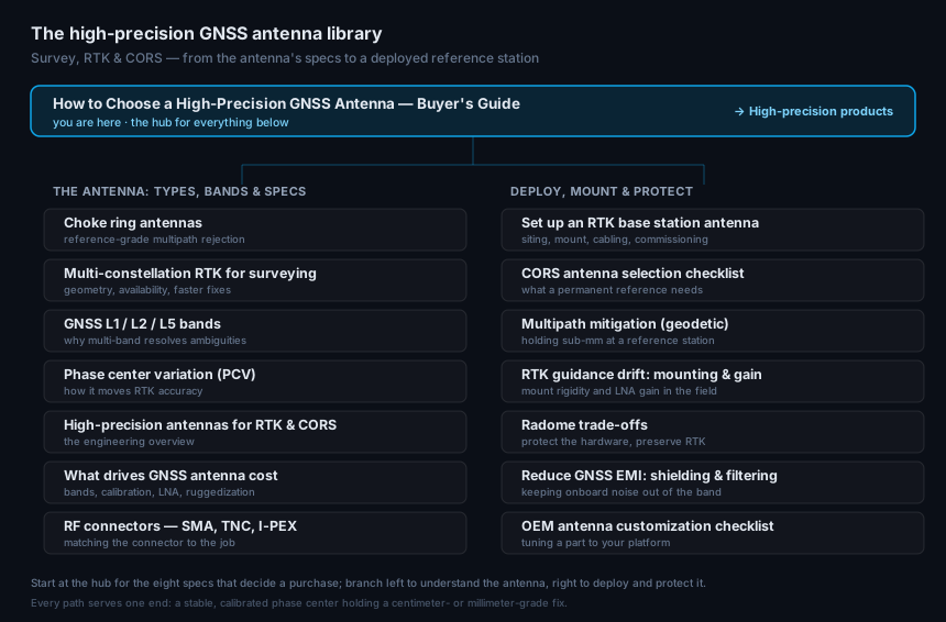
The antenna: types, bands & specs
- Ultimate guide to choke ring antennas — reference-grade multipath rejection
- Multi-constellation GNSS RTK for surveying — geometry, availability, and faster fixes
- GNSS L1 / L2 / L5 bands — why multi-band resolves ambiguities
- Phase center variation (PCV) and RTK accuracy — how it moves your solution
- High-precision antennas for RTK & CORS — the engineering overview
- What drives GNSS antenna cost — bands, calibration, LNA, and ruggedization
- GNSS antenna RF connectors — SMA, TNC, I-PEX — matching the connector to the job
Deploy, mount & protect
- How to set up an RTK base station antenna — siting, mount, cabling, commissioning
- CORS GNSS antenna selection checklist — what a permanent reference needs
- Multipath mitigation for geodetic reference stations — holding sub-mm at a reference station
- RTK guidance drift: mounting & gain — mount rigidity and LNA gain in the field
- GNSS antenna radome trade-offs — protect the hardware, preserve RTK
- How to reduce GNSS EMI: shielding & filtering — keeping onboard noise out of the band
- OEM GNSS antenna customization checklist — tuning a part to your platform
When you’re ready to spec hardware, the high-precision measurement antenna line is built for survey, RTK, and CORS.
References and further reading
Primary sources (Interface Control Documents and standards):
-
IS-GPS-200 / IS-GPS-705 (GPS L1/L2/L5 signal definitions): https://www.gps.gov/technical/icwg/
-
Galileo OS SIS ICD v2.1: https://www.gsc-europa.eu/sites/default/files/sites/all/files/Galileo_OS_SIS_ICD_v2.1.pdf
-
BeiDou ICD v3.0: http://en.beidou.gov.cn/SYSTEMS/ICD/
-
QZSS Service Definitions: https://qzss.go.jp/en/overview/services/
-
ESA Navipedia (GLONASS and NavIC signal plans): https://gssc.esa.int/navipedia/
IGS and NGS calibration ecosystem:
-
IGS Antenna Working Group: https://igs.org/wg/antenna/
-
Current ANTEX file
igs20.atx: https://files.igs.org/pub/station/general/igs20.atx -
NGS ANTCAL portal: https://geodesy.noaa.gov/ANTCAL/
-
ANTEX format specification: https://files.igs.org/pub/data/format/antex14.txt
Peer-reviewed papers cited:
-
Tranquilla, J.M. & Colpitts, B.G. (1989), “GPS Antenna Design Characteristics for High Precision Applications,” ASCE Journal of Surveying Engineering, 115(1), 2–14.
-
Wübbena, G., Schmitz, M., & Boettcher, G. (2017), “Group delay variations of GPS transmitting and receiving antennas,” Journal of Geodesy, 91(9). https://link.springer.com/article/10.1007/s00190-017-1012-3
-
Hamza, V. et al. (2024), “Cost-effective real-time kinematic positioning solutions: review,” GPS Solutions. https://link.springer.com/article/10.1007/s10291-024-01686-8
-
Lin, J. et al. (2022), “GNSS antenna multipath suppression review,” International Journal of Antennas and Propagation. https://onlinelibrary.wiley.com/doi/10.1155/2022/1527674
Engineering reference articles:
-
GPS World — “Innovation: GNSS antennas”: https://www.gpsworld.com/innovation-gnss-antennas/
-
GPS World — “Inside the box: GNSS antenna designs”: https://www.gpsworld.com/inside-the-box-gnss-antenna-designs/
-
Inside GNSS — “Making sense of GPS inter-signal corrections”: https://insidegnss.com/making-sense-of-gps-inter-signal-corrections/
-
Emlid — “Eight common mistakes in GNSS surveying”
Market data:
-
EUSPA EO and GNSS Market Report 2024: https://www.euspa.europa.eu/sites/default/files/2024-03/euspa_market_report_2024.pdf
-
High-precision GNSS antenna market sizing: Valuates Reports, 2025
Want more technical depth on individual concepts? See the GNSource Glossary — 30 entries covering everything from phase center and multipath to PPP, CORS, and CRPA anti-jamming arrays. Several entries include interactive widgets to visualise the underlying physics.