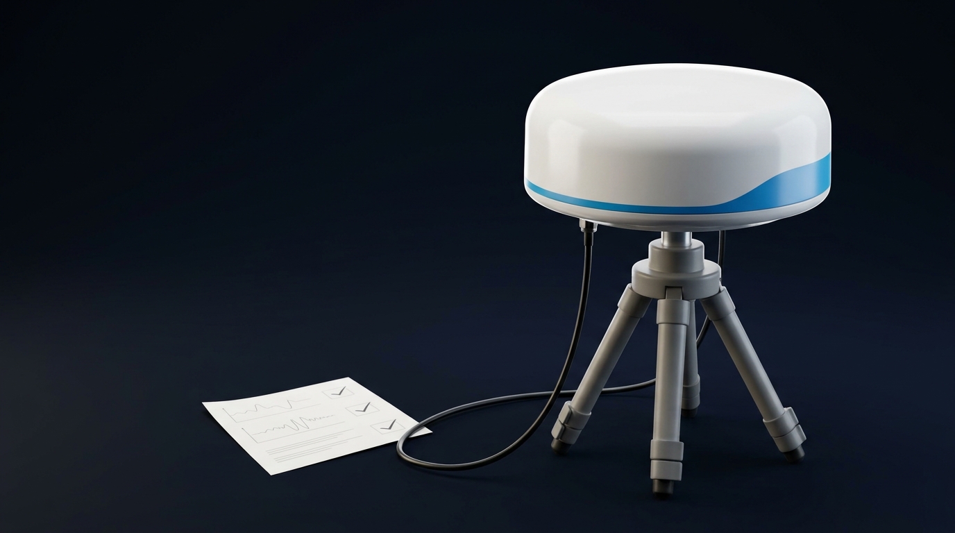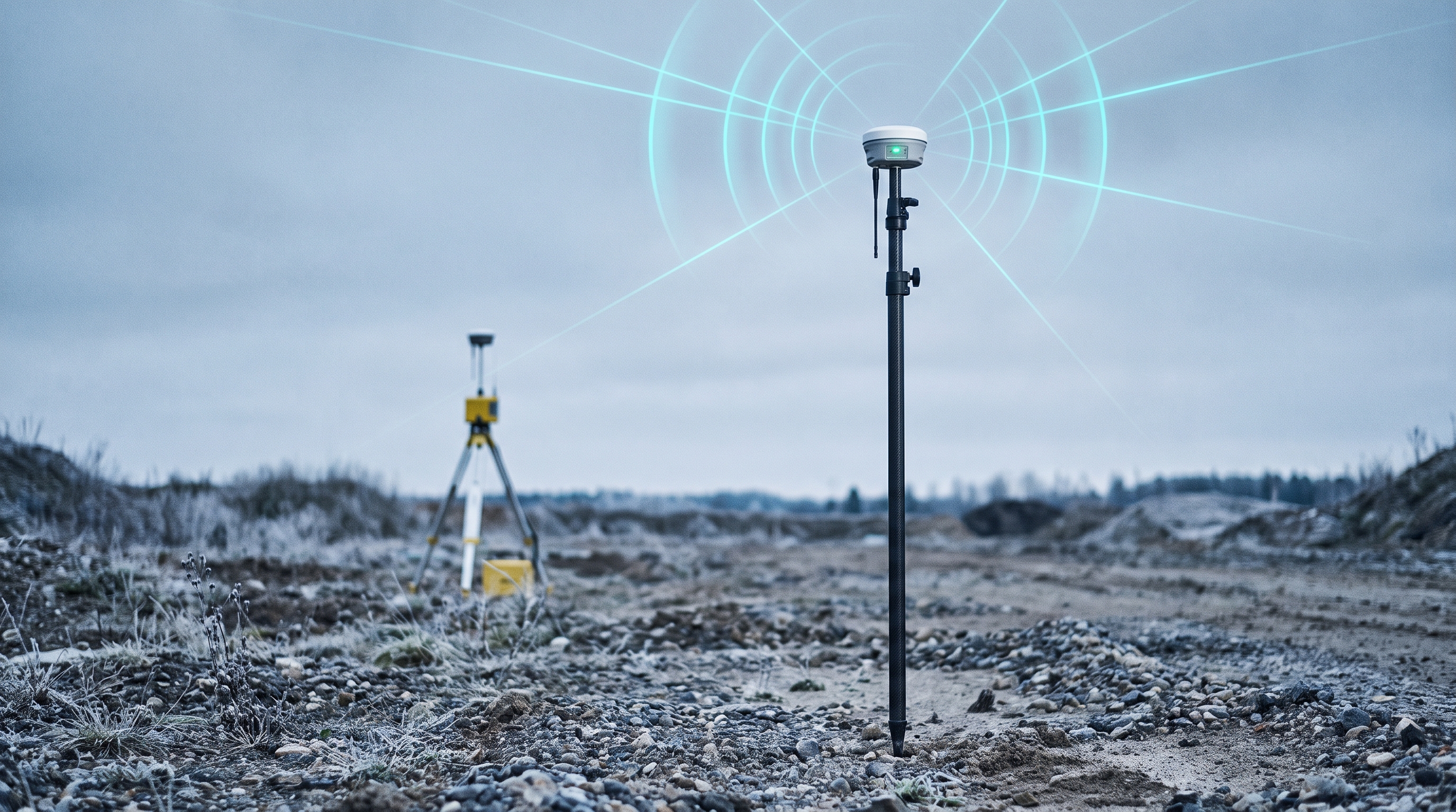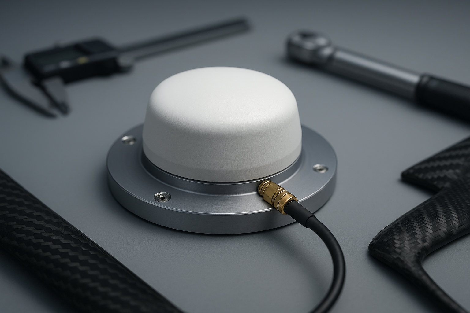
Real talk: most RTK problems I see on commercial drones don’t start in the receiver—they begin at the antenna. A patch placed on a compromised ground plane, a radome that adds phase error, or a thin coax run with the wrong connector can push a solid design into “fix won’t hold” territory. This OEM GNSS antenna customization checklist is what my team and I use to get from prototype to stable production—focusing on frequency tuning, form factor and ground plane, radome choices, and cables/connectors. Use it to prevent the usual surprises and protect RTK accuracy when the airframe, electronics, and RF all converge. Before customizing, it helps to have the baseline choice nailed—see our high-precision GNSS antenna buyer’s guide.
Why customization makes or breaks RTK on drones
On compact airframes, the antenna isn’t an isolated component—it’s part of a coupled RF system. A few principles I keep front and center:
-
Phase-center variation (PCV) matters as much as gain once sensitivity is adequate. Your RTK engine’s position is tied to the antenna’s realized phase center. Absolute PCV models and how your receiver applies them are critical, as summarized in the National Geodetic Survey’s Real‑Time User Guidelines, which describe the role of adopted PCV corrections in practice: see the discussion in NGS Real‑Time User Guidelines v2.1.
-
Radomes and mounts detune and bend patterns. Validate performance with the radome on, mounted in situ, not just the bare element on a lab plate.
-
Ground plane symmetry controls pattern stability on patches; helicals are more forgiving where you can’t guarantee a plane.
-
EMI is relentless on drones. ESCs, DC‑DC converters, and high‑power radios spray energy across L‑band; placement and shielding are non‑negotiable. Practical layout and test guidance aligns well with u‑blox integration notes and PX4 documentation; start with the u‑blox GNSS Antennas Application Note.pdf) and the PX4 GNSS integration overview.
Common mistakes I still see on production airframes
-
Patches mounted over carbon fiber without re‑tuning the match
-
Radome material picked for cosmetics, not RF transparency
-
Long micro‑coax runs with push‑on connectors that loosen in vibration
-
GNSS mounted next to LTE/Wi‑Fi/VTX modules and high‑current harnesses
-
No absolute PCV model applied in firmware or post‑processing
-
Validation done open‑sky only, without EMI‑on or dynamic flight profiles
The OEM GNSS antenna customization checklist
-
Frequency plan and tuning
-
Confirm required bands: GPS L1/L2/L5, Galileo E1/E5a/E5b, BeiDou B1/B2. Check antenna datasheet and receiver front‑end limits.
-
Measure S11/return loss on the final assembly (radome on, mounted). Acceptance: clear in‑band minima with no severe shift from spec; re‑tune if bands have drifted due to the airframe or radome.
-
Verify axial ratio and pattern symmetry at boresight and off‑axis; spot-check L5/E5 because thicker materials and mounts can skew it.
-
Ensure an absolute PCV calibration model is available for your antenna and is applied by the receiver or in post. Log to confirm the model is recognized.
-
-
Radome and housing
-
Prefer low‑loss, low‑εr materials with uniform thickness. PTFE and PTFE‑glass composites are proven low‑loss options at microwave; see the dielectric behavior of PTFE‑based laminates in Rogers RT/duroid 5880 (data sheet context at 10 GHz).
-
Avoid thick fiberglass/epoxy walls or high‑loss plastics unless tested thin and uniform; mixed fillers, paints, and adhesives can detune.
-
Validate assembled performance: re‑measure S11, compare C/N0 distributions with and without the radome, and confirm no pattern lobes that raise multipath risk.
-
-
Mounting and ground plane
-
For patch antennas, use the largest continuous, symmetric conductive ground plane you can fit. Keep slots and large cutouts away from the patch footprint. u‑blox’s integration guidance reflects these best practices in their GNSS Antennas note.pdf).
-
If the airframe’s carbon fiber is the plane, treat it as conductive: re‑tune on the final stack‑up. When a proper plane isn’t feasible, consider a helical antenna to reduce plane sensitivity.
-
Dual‑antenna heading: identical antennas, identical ground planes, matched orientations, and spacing ≥30 cm as reflected in PX4 Septentrio/u‑blox heading guidance.
-
-
Cables and connectors
-
Keep coax short and track a loss budget at L‑band. For planning, Times Microwave’s catalogs are a good baseline; typical per‑meter attenuation for common sizes sits around: RG‑178 ≈ 0.9–1.4 dB/m, RG‑316 ≈ 0.6–1.0 dB/m, and LMR‑100 ≈ 0.4–0.7 dB/m (verify exact datasheet values).
-
Favor foil+braid shield constructions when runs get longer or EMI is hostile. Threaded connectors (SMA families) with torque control outperform push‑ons in vibration. Reference torque guidance like Times Microwave connector torque requirements and lock against loosening where needed.
-
Minimize adapter count; add proper strain relief; avoid routing near switching regulators or motor phases.
-
-
EMI/EMC integration
-
Separate the GNSS antenna from VTX/LTE/5G, Wi‑Fi/BT, ESCs, and high‑current harnesses. Pedestal or wing mounts help; ensure ground continuity to the plane.
-
Power to active antennas should be filtered and low‑noise. During bench checks, run throttle sweeps and enable all radios while logging GNSS quality.
-
Use the layout and emissions/immune‑test mindset echoed in u‑blox integration manuals and PX4 assembly guidance (see the PX4 assembly notes on mounting and orientation).
-
-
Calibration and validation
-
Static open‑sky: capture C/N0 distributions per satellite, time to first RTK fix, and fixed‑state position scatter over a surveyed mark.
-
EMI‑on bench: throttle sweeps, radios on, log cycle‑slip counts and fix retention.
-
Dynamic flight: mission‑representative profile; measure fixed availability, fix reacquisition times, and baseline repeatability across flights.
-
Confirm the receiver is applying the correct antenna model/PCV corrections, consistent with the approach described by NGS Real‑Time User Guidelines v2.1.
-
-
Production and reliability
-
Establish a golden‑sample baseline: S11 curves, axial ratio snapshots, and field metrics (C/N0 distributions, TTFF, fix retention) to compare lots.
-
Define torque specs for all RF connectors and document anti‑loosening methods. Track cable/connector lots and lengths.
-
Run environmental screens aligned to themes from DO‑160/MIL‑STD‑810 for vibration and temperature exposure; record pass/fail criteria and margins.
-
Field scenario: two radomes, one airframe — what changed in RTK
We evaluated a tri‑band patch on the same multirotor top plate with two production‑ready radomes. Radome A used a thin, PTFE‑like shell with tight thickness control. Radome B was a thicker fiberglass/epoxy part chosen for mechanical stiffness.
Both assemblies met band coverage on a VNA in bare‑element tests. On the final airframe, Radome B showed a small return‑loss shift on L5/E5 and a subtle broadening of the main lobe. In open‑sky static logs, satellites at lower elevations exhibited slightly lower C/N0 with Radome B. During throttle sweeps with the VTX enabled, the RTK engine on Radome A held fixes more consistently, while the Radome B assembly showed occasional float events that correlated with the EMI‑on periods.
The takeaway wasn’t “PTFE always wins”—it was to validate the assembled antenna with the intended radome and mount, then lock the design only after flight logs confirm fix availability and stability across your mission profile.
Practical example — vendor‑supported workflow
On one program, we needed dual‑frequency coverage with strict PCV stability on a tight airframe. We engaged a vertically integrated vendor to co‑tune the element on our actual carbon‑fiber top plate, validate with the production radome, and run environmental screens before DVT. GNSource can support this kind of workflow by iterating RF tuning on the final ground plane, characterizing axial ratio and beam symmetry, and verifying absolute PCV behavior under the chosen radome. The key value in practice was speed: having tuning, simulation, and anechoic measurements under one roof shortened loops between design intent and measured results, which made it much easier to freeze the build before PVT.
Cable loss quick reference and connector notes
Below is a planning‑level reference. Always replace with your selected cable’s datasheet values.
Cable type | Typical attenuation at L‑band (per meter) | Shielding construction |
|---|---|---|
RG‑178 | ~0.9–1.4 dB/m | Single braid |
RG‑316 | ~0.6–1.0 dB/m | Single braid |
LMR‑100‑class | ~0.4–0.7 dB/m | Foil + braid |
For vibration‑prone airframes, use threaded connectors with defined torque and anti‑rotation. Push‑on micro connectors (U.FL, MMCX) need mechanical retention at minimum; many teams avoid them entirely on the antenna side in favor of SMA‑family interfaces with locking hardware.
Validation recipe you can repeat on every build
-
Bench: VNA S11 with radome on and mounted; power the active antenna and check current/noise.
-
Open‑sky: 30–60 minutes logging; compute C/N0 distributions, TTFF to RTK fix, and fixed scatter vs a survey point.
-
EMI‑on: Throttle sweeps and all radios on; monitor cycle slips and fix retention.
-
Flight: Mission‑representative profile; track fixed availability and reacquisition times. If any regression appears, isolate by swapping radomes, ground planes, or cable assemblies one variable at a time.
FAQ
Do I need L5/E5 for commercial drones, or is L1/L2 enough
If your operating area has good L5/E5 availability, the additional frequency can improve multipath robustness and fix resilience. That said, adding bands only helps if the antenna, radome, and integration preserve clean patterns and low PCV. Validate on your missions before committing.
How big should the ground plane be on a small multirotor
Bigger and more symmetric is generally better for patches. Many 25–35 mm patches are validated on 50–70 mm plates in vendor notes, but you should re‑tune on the actual airframe and confirm in logs. If you can’t guarantee a plane, consider a helical antenna.
What radome material should I choose
Prioritize low‑loss, low‑εr materials with uniform thickness. PTFE‑based constructions have consistently low loss in RF applications (see Rogers RT/duroid families for representative behavior). Prove it on your antenna and mount—measure S11, then compare C/N0 and fix stability in flight.
How far apart should dual antennas be for heading
Keep spacing at least 30 cm with matched ground planes and orientations. Check system docs for your receiver, and verify heading stability in dynamic tests on your platform.
How do I know if my PCV model is applied
Confirm the antenna model selection in the receiver configuration and verify in logs that the expected corrections are in use. If possible, compare results with and without the model to see the effect on baseline repeatability.