
A launch vehicle is one of the most hostile places you can ask a GNSS antenna to work, and one of the most safety-critical. From the moment it clears the pad, GNSS feeds the system that decides whether the flight should be terminated, tracks the vehicle for the range, and helps steer it to orbit. The antenna has to hold a usable signal through a rolling, accelerating, violently shaking ascent — and it cannot drop the fix at the wrong moment, because the wrong moment might be a flight-termination decision.
This is not the same problem as a survey rover or a car. Launch GNSS is specialized by three things at once: extreme dynamics, a brutal mechanical environment, and export-control rules written specifically to keep GPS out of missiles. This guide covers what GNSS does on a launch vehicle, why the ascent tries so hard to break it, and what the antenna has to do — and survive — to keep working.
Why launch GNSS isn’t consumer GNSS
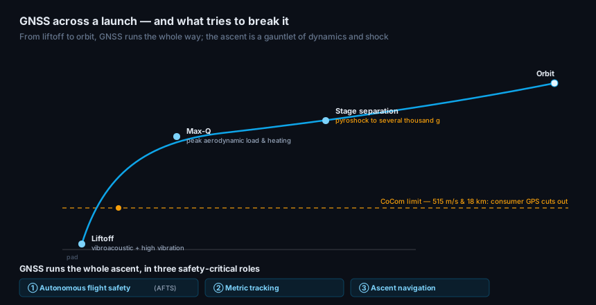
Three things separate a launch antenna-and-receiver chain from anything on the ground.
The first is dynamics. A rocket accelerates through several g and climbs past several kilometres per second, and the rate of change — jerk — spikes at ignition, staging, and burnout. That translates into large, fast-changing Doppler shifts the receiver has to track, and it means the antenna is never pointed the same way for long.
The second is export control. Under the long-standing CoCom rules, a civilian GPS receiver is required to stop outputting a navigation solution once it is moving faster than about 515 m/s (1,000 knots) and higher than about 18 km (60,000 ft) — limits designed to keep GPS out of ballistic missiles. A launch vehicle blows through both within the first couple of minutes. So launch GNSS uses receivers cleared of those limits — ITAR-controlled, export-licensed, aerospace- and defense-grade equipment — a category most commercial GNSS parts never enter.
The third is the environment, which is severe enough to deserve its own section.
What GNSS does on a launch vehicle
GNSS is not a convenience on a launch vehicle; it is safety infrastructure, running in three roles at once.
Autonomous flight safety. Modern ranges increasingly rely on an Autonomous Flight Termination System (AFTS), also called an Autonomous Flight Safety System. Redundant onboard processors fuse GPS and inertial data to track the vehicle’s position and velocity, and if it violates its safety corridor, the system terminates the flight itself — no ground radar, no human range-safety officer in the loop. NASA describes AFTS as using “on-board real-time data and encoded logic to determine if the flight should be self-terminated”, replacing the ground personnel and infrastructure that used to do it. Because it is safety-critical and autonomous, it wants redundant, independent navigation — which is a strong argument for multi-constellation, multi-band reception at the antenna.
Metric tracking. The same GPS position and velocity provide the range’s authoritative record of where the vehicle is — GPS metric tracking that has largely displaced ground-based tracking radar for the ascent.
Ascent navigation. GNSS also feeds the vehicle’s own guidance, correcting inertial drift so the trajectory and orbit-insertion burns land where they should.
All three run continuously from liftoff, and all three depend on the antenna holding a signal through the climb.
The launch environment
The ascent is a gauntlet of mechanical abuse, and the antenna is bolted to the outside of it.
At liftoff, the vehicle sits in an intense vibroacoustic field — the engine and reflected acoustic energy shake the whole structure with broadband random vibration. Through max-Q, aerodynamic pressure and heating peak. At every stage separation, pyrotechnic devices fire, and the resulting pyroshock is brutal: transient accelerations that can reach several thousand g over milliseconds. Across the whole flight, the antenna sees a temperature swing from ground ambient through aerodynamic heating.
Any of these can crack a solder joint, detune an element, or shift a phase center. So a launch antenna is qualified against standards built for exactly this: MIL-STD-810 for environmental and shock, DO-160 for airborne-equipment vibration and environment, the range’s own RCC flight-termination requirements, and NASA-style vibroacoustic screening. Qualification is not paperwork here — it is the evidence that the part will still radiate cleanly after the shock that separates the first stage.
The antenna problem: coverage through the roll
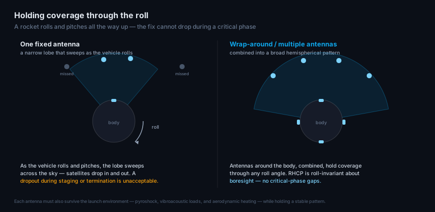
Beyond survival, the antenna has a geometry problem the ground never poses: the vehicle is moving relative to the sky the entire time. A rocket rolls about its long axis and pitches over through a gravity turn, so an antenna’s pattern is constantly reorienting against the satellites. A single fixed element with a directional lobe would sweep that lobe across the sky, dropping satellites in and out — and a dropout during staging or a termination decision is exactly what cannot happen.
The answer is broad, gap-free coverage. Launch vehicles use multiple antennas around the body — or a wrap-around design — combined so their patterns overlap into a near-hemispherical whole that keeps satellites in view at any roll angle. Right-hand circular polarization helps, because RHCP is invariant to roll about the boresight, but attitude change still demands a wide pattern with no deep nulls. Getting there without ripple or coverage holes — while surviving the launch loads — is the core RF design challenge.
Where the antenna fits
Everything above lands on a handful of antenna requirements, and they are why a launch antenna is a purpose-built part, not a hardened commercial one:
- Broad, gap-free hemispherical coverage so the fix holds through roll and pitch, delivered by a wrap-around or multi-antenna arrangement.
- Multi-band, multi-constellation reception to give the autonomous flight-safety system the independent, redundant measurements it needs.
- Survival of the launch environment — pyroshock to thousands of g, vibroacoustic loads, and aerodynamic heating — verified by environmental qualification, the same vibration, shock, and temperature discipline that governs any high-reliability airborne antenna, taken to launch levels.
- A stable phase center and clean pattern under load, so the tracking and termination logic can trust the measurement.
- A low-profile, conformal form factor that respects the vehicle’s aerodynamics.
This is squarely defense-and-aerospace-grade hardware, and it overlaps directly with the high-dynamics, contested-environment antennas in the defense and military line — high-dynamics platform and airborne designs built for exactly these loads.
Frequently asked questions
Why can’t a launch vehicle use a normal GPS antenna and receiver? Two reasons. Export control: civilian GPS receivers are required to stop outputting a solution above roughly 515 m/s and 18 km — limits a rocket exceeds in its first minutes — so launch uses ITAR-controlled, aerospace-grade equipment cleared of them. And environment: the antenna must survive pyroshock to thousands of g, vibroacoustic loads, and aerodynamic heating while holding a stable pattern, which a commercial part is not built or qualified to do.
What is an Autonomous Flight Termination System (AFTS)? It is an onboard, self-contained range-safety system. Redundant processors fuse GPS and inertial navigation to track the vehicle and autonomously terminate the flight if it leaves its safety corridor — no ground radar or human range-safety officer required. Because it is safety-critical, it favors redundant multi-constellation, multi-band GNSS, which starts at the antenna.
Why do rockets use wrap-around or multiple antennas? Because the vehicle rolls and pitches throughout ascent. A single fixed antenna’s pattern would sweep across the sky and drop satellites in and out; multiple antennas around the body, combined, hold a broad hemispherical pattern that keeps satellites in view at any roll angle — so the fix never drops during a critical phase.
How is a launch GNSS antenna qualified? Against launch-representative environmental standards — MIL-STD-810 for shock and environment, DO-160 for airborne vibration, the range’s RCC flight-termination requirements, and vibroacoustic screening. Qualification proves the antenna still radiates cleanly after the vibration of liftoff and the pyroshock of stage separation.
Does GNSS work in space after orbit insertion? Yes — GNSS is widely used in low Earth orbit for spacecraft navigation, using antennas pointed outward toward the GNSS constellations above. That is a distinct design from the ascent antenna, and orbital use adds its own space-grade concerns (radiation, outgassing) on top of the launch environment.
Written by GNSource Engineering. GNSource manufactures high-dynamics, ruggedized GNSS antennas for aerospace, launch, and defense platforms. Talk to our engineers about a launch- or high-dynamics antenna, or explore the defense & military line.