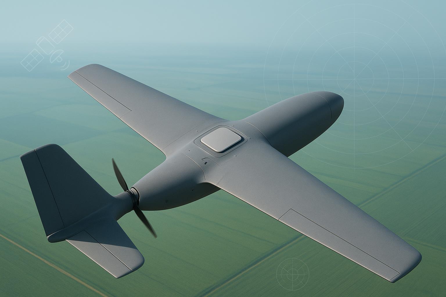
If you’ve ever watched a multirotor hold a rock‑solid RTK fix on the ground and then lose it mid‑flight, you know the feeling: everything looked fine on the bench, yet cycle slips spike when the motors spin up, time‑to‑fix stretches, and the baseline drifts a few centimeters. In every root‑cause analysis I’ve done, the pattern is the same—datasheet specs were correct, but the installed antenna assembly (radome, backshell, pigtail, mount) wasn’t environmentally qualified for the airframe.
This isn’t about surviving rain or a marketing “rugged” label. It’s about carrier‑phase stability under vibration, shock, and temperature swings, and whether the assembly stays sealed and electrically solid after stress. That’s what GNSS antenna environmental qualification actually tests—the ruggedness layer of the broader UAV GNSS antenna selection & integration guide.
What “GNSS antenna environmental qualification” really covers
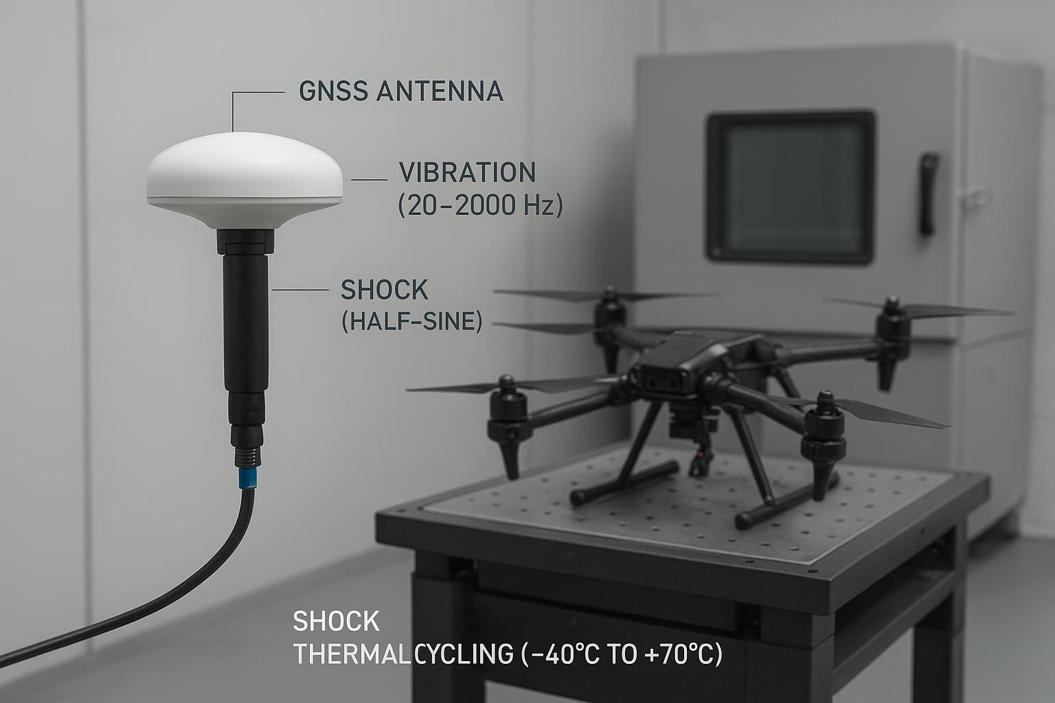
Environmental qualification spans four buckets and how they translate to phase tracking:
-
Vibration: broadband random (often 10/20–2,000 Hz) excites mast/boom resonances and any mechanical play at the connector or mount. Micro‑motions show up as intermittent phase noise and cycle slips. Tailor tests per MIL‑STD‑810H Method 514.8 guidance for subassemblies or RTCA DO‑160 Section 8 for aircraft installations. See the accessible overview in the CVG Strategy Method 514.8 summary.
-
Shock: landing shocks and handling impacts can open micro‑gaps in a backshell or de‑bond adhesives. Use MIL‑STD‑810H Method 516.8 half‑sine pulses as a screen; CVG Strategy’s 810H overview outlines the method family.
-
Thermal cycling: −40 °C to +70/85 °C ranges with dwells, repeated 50–100 times, expose CTE mismatch. If the effective phase center creeps or a seal hardens, you may see a persistent baseline bias or elevated residuals after the chamber run.
-
Ingress (IP): IEC 60529 defines IP codes like IP67/IP68, but they say little about vibration‑induced seal wear or connector leakage after stress. See IEC 60529. Treat IP as necessary but not sufficient; always re‑verify sealing after vibe/thermal.
In short, GNSS antenna environmental qualification isn’t a checkbox; it’s proof that the installed assembly keeps carrier‑phase tracking clean when the airframe is doing real work.
Why this matters for UAV RTK performance
Carrier‑phase RTK lives or dies on three things: stable phase center, adequate C/N0, and continuous lock. Vibration, shock, and temperature swings attack all three.
-
Phase‑center stability: Even sub‑millimeter shifts matter. For CORS‑grade systems, geodetic antennas target ~±1 mm repeatability in rotation and thermal sweeps. That’s why selection and installed stiffness matter, and why a post‑cycle baseline comparison is mandatory.
-
C/N0 and microphonics: Cable motion and poorly supported pigtails act like microphones, modulating the RF front end. You’ll see a 1–2 dB‑Hz average C/N0 drop under vibration with inadequate strain relief, and often a coincident uptick in slip flags.
-
Lock continuity and fixed fraction: The quickest tell in logs is the fixed/float ratio. Under stress, fixed fraction drops as slips accumulate and time‑to‑fix stretches. Your acceptance band should cap slip rates under the representative Grms spectrum and keep the post‑stress fixed fraction close to pre‑stress values.
For airborne programs, I use DO‑160 for installation‑level assessments (airframe location, rotor/prop spectra) and MIL‑STD‑810H as a practical bench framework for subassembly screening. RTCA’s public page explains the scope at a high level: RTCA DO‑160.
A reproducible lab + field scenario (with acceptance criteria)
Here’s a test recipe we’ve run on small hybrid UAV programs that you can reproduce in a week. Think of it as a sanity screen for your entire installed antenna assembly before flight hours pile up.
Platform and setup
-
Airframe: 3‑rotor hybrid UAV, composite fuselage, top‑mounted 150 mm mast.
-
Site: open‑sky test range with a surveyed base. Short baseline ≈ 1 km.
-
Antenna: multi‑frequency RHCP survey antenna with sealed backshell and 5 m low‑loss coax to the receiver.
-
Logging: record per‑satellite C/N0, slip events, fixed/float, and baseline errors at ≥1 Hz with all avionics powered.
Pre‑stress baseline (10 minutes static)
- Average C/N0 ≈ 47 dB‑Hz, fixed fraction 98%, baseline RMS 0.012 m (horizontal).
Random vibration (bench, 3 axes, 1 h/axis)
- Profile: 20–2,000 Hz random tailored from MIL‑STD‑810H 514.8. Monitor slip flags during run. With weak strain relief on the pigtail, we saw 0→2 slips/hour; proper damping cut this to <0.1/hour.
Shock (bench)
- Half‑sine 20–30 g, 11–18 ms, 3 hits per direction (±X/±Y/±Z). Re‑inspect connector torque and seals post‑sequence.
Thermal cycling (chamber)
- Range: −40 °C to +70 °C, 30‑minute dwells, 50 cycles. After 50 cycles, a marginal backshell once produced intermittent phase noise that raised post‑test RMS.
Post‑stress baseline (10 minutes static)
- Observed case before rework: baseline RMS 0.018 m, fixed fraction 92%, small but visible C/N0 reduction under rotor spin‑up.
Acceptance criteria (tailor for your program)
-
Post‑stress baseline RMS ≤ 0.02 m (1 km baseline, open sky, avionics powered).
-
Fixed fraction ≥ 95% in the same conditions.
-
Slip rate during representative vibration < 0.1 slips/hour.
-
Average C/N0 drop ≤ 1–2 dB‑Hz vs pre‑stress.
Standards references that frame this approach: MIL‑STD‑810H vibration 514.8 summary and DO‑160 Section 8/5 for installation‑level tailoring via RTCA DO‑160.
Common integration mistakes that sink RTK
-
Assuming an IP67 label covers vibration/thermal realities—seals can fail after stress; always re‑test sealing.
-
Under‑torqued backshells and no strain relief—micro‑gaps turn into phase noise and slip bursts during rotor harmonics.
-
Mounts that resonate in the 20–2000 Hz band—your shaker finds it before the first flight should.
-
Patch antennas on tiny ground planes—great S11 on the bench, poor axial ratio and multipath resilience in the air.
-
Coax routed alongside ESC power or telemetry radios—expect C/N0 dents and intermittent lock under load.
-
“Receiver looks fine on the desk” syndrome—log with avionics powered and props spinning in a safe fixture.
Practical improvement checklist for production deployment
- Selection and phase‑center stability
- Choose antennas with documented PCV/phase‑center stability appropriate to your mission. For CORS‑like references, geodetic/choke ring models target sub‑millimeter repeatability; for weight‑constrained UAVs, high‑quality survey antennas are the norm. Trimble’s choke ring families illustrate geodetic repeatability in public docs, and GNSource’s high‑precision line describes sub‑millimeter phase‑center stability for its flagship geodetic models; use these as selection anchors and then validate on your airframe. See Trimble choke ring information and the GNSource High‑Precision Measurement page.
- Mounting stiffness and torque discipline
- Use a rigid adapter and verify torque on the antenna base and backshell. Add thread‑locker where allowed. If you can twist the mast by hand, your vibe profile will twist it more.
- Ground plane or isolation
- For patches, follow ground‑plane guidance (u‑blox and Taoglas notes). For mast‑mounted survey antennas, ensure clean isolation from conductive clutter and avoid partial ground planes that skew the pattern. References: u‑blox GNSS antenna app note.pdf) and ESA Navipedia: GNSS antennas — patch types and ground‑plane effects.
- Cable selection and routing
- Use low‑loss, 50 Ω coax with proper connectors; avoid tight bends near the antenna; bond shields at the receiver; separate from ESC power and RF emitters. NovAtel’s integration notes remain a solid reference.
- Strain relief and damping
- Add pigtail loops or clamps with elastomer damping. This alone has dropped our slip rate during vibration by an order of magnitude in marginal builds.
- EMI spacing
- Keep the antenna and first 30–50 cm of coax away from ESCs, switching regulators, and telemetry radios. Validate by powering everything and watching the C/N0 trend.
- Firmware and logging discipline
- Ensure the receiver outputs per‑satellite C/N0, slip flags, fix/float, and baseline components at ≥1 Hz. Save raw data before and after stress so you can compare residuals and fixed fraction.
- Bench vibration and shock screen
- Run the 810H‑tailored vibe/shock screen on the installed assembly early. It’s cheaper to fix a backshell in the lab than after a crash investigation.
- Thermal cycling and post‑cycle re‑torque
- 50–100 cycles from −40 °C to +70/85 °C with dwells. Re‑torque connectors and re‑inspect seals after the chamber. Then re‑run your baseline.
- Installation‑level check on the target airframe
- Close with a DO‑160‑style installation check: capture the actual rotor/prop spectrum and verify metrics in hover and forward flight.
GNSource micro‑example (neutral, practical): On UAV builds where a geodetic choke ring is impractical, we’ve used lightweight, multi‑frequency survey antennas with IP67 sealing and −40 to +85 °C ratings from vendors whose documentation includes phase‑center stability claims. For instance, when short‑listing options we’ve referenced the GNSource Aviation/UAV page for packaging and environmental ranges and the GNSource High‑Precision Measurement page for phase‑center language, then validated the selected antenna on a 20–2,000 Hz shaker with pigtail strain relief and post‑cycle baseline checks. Keep the tone of your internal report factual: list torque values, O‑ring condition, and before/after metrics rather than vendor adjectives.
If your application leans into harsher profiles (missile‑borne, heavy‑shock landing), it’s worth skimming ruggedization overviews to align expectations with military practice; vendors often summarize methods adjacent to MIL/GJB claims—for context on environmental ranges and packaging practices in defense lines, see GNSource’s Defense/Military page.
Minimal data you should always log (CSV template)
Below is a lean template I hand to test engineers. Keep it simple and consistent across pre‑/during‑/post‑stress runs.
column | description |
|---|---|
timestamp | UTC time (s) |
prn | Satellite ID |
elevation_deg | Satellite elevation |
azimuth_deg | Satellite azimuth |
cn0_dbhz | Carrier‑to‑noise density (dB‑Hz) |
slip_flag | 0/1 indicator per epoch |
fix_state | fixed/float/none |
baseline_e_m | East error (m) on 1 km short baseline |
baseline_n_m | North error (m) |
baseline_u_m | Up error (m) |
temp_c | Chamber or ambient temperature (°C) |
axis | Axis under test (X/Y/Z/flight) |
vibration_grms | Shaker level if applicable |
Plot tips: per‑satellite C/N0 traces, cumulative slip count over time, fixed fraction per minute, and baseline E/N histograms before vs. after stress. The contrast will tell you more than a paragraph of prose.
FAQ
Q: Should I use DO‑160 or MIL‑STD‑810H for a small UAV antenna? A: Use 810H to bench‑screen the antenna/radome/backshell/pigtail as a subassembly. Then do a DO‑160‑style installation validation on the target airframe using its measured vibration spectrum. See RTCA DO‑160 and the MIL‑STD‑810H vibration summary for frameworks.
Q: Is IP67 enough for drones? A: It’s necessary, not sufficient. IP67/68 validate water/dust ingress under specific conditions but don’t guarantee integrity after vibration and temperature cycling. Always re‑check sealing after environmental stress. Reference IEC 60529.
Q: How much C/N0 drop is acceptable under vibration? A: As a screening limit, keep average C/N0 drop within 1–2 dB‑Hz compared to pre‑stress, open‑sky, avionics‑powered conditions—and ensure slip rate stays <0.1/hour on your representative profile.
Q: When should I re‑test an antenna installation? A: After any hard landing, connector service, or airframe change that affects the mount or cable routing. A 30‑minute baseline + short vibe screen is cheap insurance.
Next steps
If you want a starting point for short‑listing hardware, the GNSource Aviation/UAV page lists packaging and environmental ranges you can map to your shaker/thermal plan; validate everything on your airframe.