On a midsummer field test, we watched median C/N0 sag by ~1 dB the moment rotors came up to full RPM. Ten minutes later, after a hot hover, cycle slips ticked upward on low‑elevation satellites and time‑to‑refloat doubled after a brief masking event. Nothing on the bench predicted it. The culprit wasn’t the RTK stack—it was the environment: vibration, shock handling, and temperature driving real RF and timing changes at the antenna, cable, and receiver. This is the part of integration that quietly decides whether your UAV holds a fix or spends the day chasing it. It’s one layer of the broader UAV GNSS antenna integration guide.
Why vibration, shock, and temperature environmental specs matter for GNSS/RTK on drones
Carrier‑phase RTK lives or dies on phase stability. Three things move it in airborne platforms:
-
Phase‑center variation (PCV) and axial ratio: Small antennas without published PCV can wander by several millimeters as the angle of arrival changes or the element detunes under thermal/mechanical stress. High‑grade rover antennas document PCV at the ±1–3 mm class; ESA and GPS World reported total PCV under ~3 mm for a novel rover design—see the engineering feature in GPS World’s Innovation section and the ESA NAVISP paper for context: Innovation: Design and performance of a novel GNSS antenna for rover applications (GPS World/ESA, 2023) and ESA NAVISP technical PDF.
-
Mount resonance and soft damping trade‑offs: A flexible mast or a mount that rings at prop/motor harmonics can modulate the antenna attitude and cable, injecting phase noise. Soft mounts tamp down high‑frequency vibration but can introduce low‑frequency attitude “wobble,” which shows up as heading jitter in dual‑antenna systems.
-
Thermal effects in the RF front end: LNA noise figure drifts with temperature; a +0.5 to +1.0 dB NF increase costs you about the same in C/N0. Fundamentals behind C/N0 and thermal noise are well covered by industry references: Safran’s tutorial on measuring GNSS signal and Gaussian noise power and Wasy Research on C/N0 vs SNR; Furuno’s glossary provides the −174 dBm/Hz noise‑density reference commonly used in link budgets: Furuno GNSS glossary.
-
Oscillator stability under dynamics: TCXOs drift with temperature and have g‑sensitivity; aggressive maneuvers convert acceleration into frequency error that raises carrier‑phase jitter. Low‑g super‑TCXO or OCXO receivers reduce those excursions and help the filter ride through brief outages; see vendor overviews such as Rakon’s GNSS positioning oscillators brief and SiTime’s aerospace/defense timing page.
If you think of the RTK solution as a tightrope walker, vibration is a shove, temperature is a headwind, and a poor mount is a slippery rope. Keep all three in check and ambiguity resolution gets a lot less dramatic.
How these specs move your RTK metrics
Here’s how those mechanisms flip the visible dials:
-
C/N0 (dB‑Hz): Roughly tracks −ΔNF and added losses; even a 0.5–1.0 dB drop matters on low‑elevation satellites. The relationship is explained in the industry tutorials from Safran and Wasy Research linked above.
-
Cycle slips (per minute): Rise when phase jitter and SNR dips coincide, or when connectors intermittently lose contact under vibration.
-
Time‑to‑first‑fix (TTFF) and time‑to‑float: Increase with lower C/N0 and noisier residuals; after obstruction, re‑fix can stretch from seconds to tens of seconds depending on scene and dynamics. A 2024 paper on low‑cost drones reported typical refix around 9–13 s depending on environment: Reliability of RTK Positioning for Low‑Cost Drones (2024).
-
Phase residual RMS and heading variance: Sensitive to mount‑induced micro‑motion and PCV repeatability. You’ll see this in post‑processed residual plots and moving‑baseline heading logs.
In short: environmental specs—vibration, shock handling, and temperature—directly translate into the RTK metrics you track every flight.
Realistic flight test comparison: stiff vs soft‑damped, patch vs helical, cable quality
Test setup
-
Same airframe and RTK receiver/firmware across runs; identical logging and NTRIP.
-
Antenna configs: (A) low‑cost multiband patch on a thin mast; (B) multiband helical on a stiff, non‑resonant mount; © same as B with a tuned soft‑damped interface.
-
Cable: 1.5 m low‑loss coax with threaded connectors and strain relief.
-
Matrix: rotor‑spin ground run (65% and 100% throttle), 20 m hover, aggressive yaw/rolls, hot/cold soak.
Representative outcomes (interpret these as example numbers to guide expectations):
-
(A) vs (B): A shows ~20–30% lower median C/N0 and ~3× higher cycle‑slip rate under rotor‑spin and maneuvers; TTFF and re‑fix extend by up to 2× vs B. Phase residual RMS notably worse in A.
-
© vs (B): Soft‑damped mount reduces short, high‑frequency slips seen in B during rotor transients, but introduces low‑frequency attitude micro‑motion; heading jitter increases slightly on dual‑antenna setups. Net: C can help when the structure rings at high frequency, but it must be tuned to avoid low‑frequency excursions.
What to log (examples)
-
u‑blox F9: enable UBX‑RXM‑RAWX (≥1 Hz), UBX‑NAV‑SAT, UBX‑NAV‑PVT, UBX‑NAV‑RELPOSNED (if moving‑baseline), and UBX‑MON‑RF/HW per the official Interface Description: u‑blox F9 HPG Interface Description (UBX‑22008968).
-
Septentrio mosaic‑X5/PolaRx: MeasEpoch/MeasEpochChannel, PVTSatInfo, ChannelStatus; configure SBF logging via the vendor guides: mosaic‑X5 Reference Guide and PolaRx5 User Manual.
-
Post‑process residuals and slip flags with RTKLIB (demo5 manual) to correlate slips with throttle and airframe accelerometer traces.
Common engineering mistakes to avoid
-
Assuming bench performance equals flight performance; skipping combined vibration + thermal runs.
-
Mounting the antenna on flexible plates or near carbon fiber without measuring resonance and detuning.
-
Using thin, high‑loss micro‑coax (or snap‑on connectors) with no strain relief; fretting kills SNR.
-
Ignoring receiver oscillator class and placement; hot battery bays and compute stacks raise drift.
-
Running long coax without budgeting insertion loss and phase stability across temperature.
-
Failing to log RAW measurements, so cycle slips and C/N0 dips go unnoticed until production.
Practical improvement checklist for airborne GNSS/RTK
-
Antenna selection
- Favor antennas with published low PCV and good axial ratio across bands; treat uncalibrated patches as mm‑level unknowns and verify in flight.
-
Mounting
- Use a stiff, non‑resonant mast or plate. Sweep for resonances; keep clear sky view and separation from high‑current wiring and ESCs.
-
Cabling & connectors
- Target ≤0.5–1.0 dB total L‑band loss over 1–2 m. Use foil+braid low‑loss coax and threaded SMA/TNC; add clamps and service loops to suppress micro‑motion and meet bend‑radius limits.
-
Thermal & oscillator
- Characterize LNA NF (proxy via C/N0) and receiver oscillator drift over −20 to +60 °C (or your mission envelope). Consider low‑g super‑TCXO or OCXO receivers for high‑dynamic platforms or brief GNSS outages.
-
Firmware & validation
- Log C/N0, cycle slips, phase residuals, and RTK solution states. Instrument TTFF and time‑to‑float during environmental tests and compare to bench baselines.
Validation matrix and pass/fail heuristics (aligned to common standards)
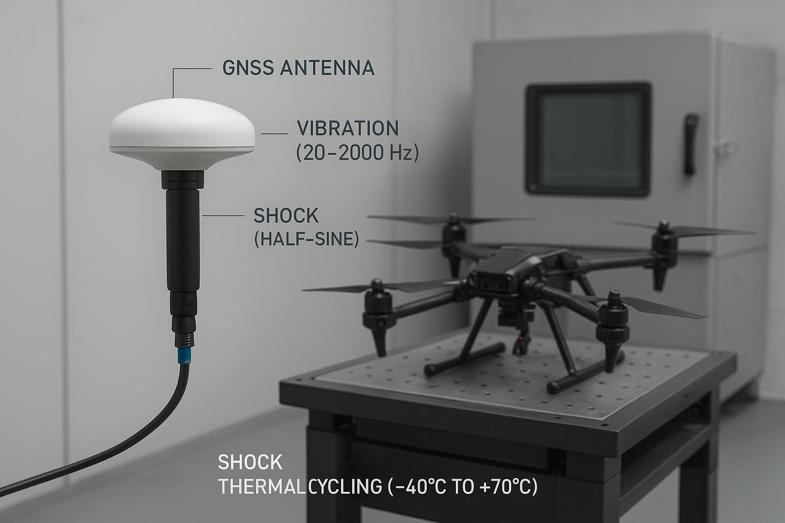
Below is a concise, testable matrix you can adapt. Use official standards for formal qualification: MIL‑STD‑810H Method 514.8 (vibration) and 516.8 (shock), and RTCA DO‑160 Section 8 for aviation‑grade vibration categories and tailoring guidance.
Environment | Test/Level (representative) | Log/Metric | Pass heuristic | When it fails | Standards context |
|---|---|---|---|---|---|
Bench thermal soak | −20 °C ↔ +60 °C, 60–90 min dwell | Median C/N0 per band; oscillator drift | ≤1 dB C/N0 loss vs room; drift within receiver spec | >3 dB C/N0 loss; frequent slips at extremes | DO‑160 Sec. 4 temp; NF/C/N0 fundamentals per Safran tutorial |
Vibration (random; axes X/Y/Z) | 5–2000 Hz, g RMS tailored to measured airframe; include sine‑on‑random if harmonics dominate | C/N0, cycle slips/min, residual RMS | Slips <0.1/min; C/N0 loss ≤1 dB vs bench | Intermittent >3 dB C/N0 dips; connector faults | MIL‑STD‑810H Method 514.8 overview (Trenton Systems); DO‑160 Section 8 summaries (Element) |
Shock handling | Half‑sine 40 g @ 11 ms (functional); repeat | Continuity, C/N0 before/after | No continuity faults; C/N0 unchanged | Intermittent contact; step change in SNR | |
Combined env. | Vibration + thermal cycling | TTFF, time‑to‑float, slips/min | TTFF/time‑to‑float ≤2× baseline; slips within spec | Refix unstable; persistent slips |
According to the C/N0 and thermal noise fundamentals linked above, a +1 dB rise in effective noise figure is approximately a −1 dB C/N0 loss, which explains why hot soaks visibly move your plots.
Practical example: using a multiband helical on a stiff mount (GNSource)
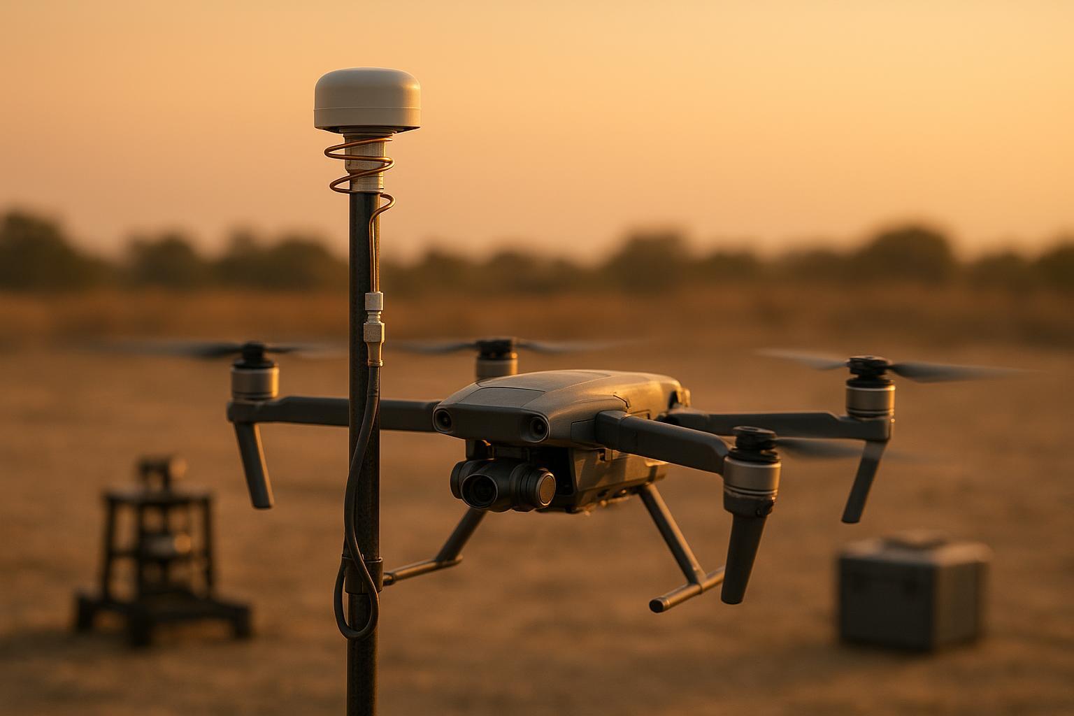
On a 5–7 kg mapping UAV that previously flew a compact patch on a thin composite plate, we swapped to a multiband helical on a stiff aluminum/carbon post, routed a 1.5 m low‑loss coax with threaded connectors, and added proper strain relief at both ends. We ran a simple sequence: rotor‑spin to 100% for 60 seconds, 20 m hover for 3 minutes, a set of yaw/roll maneuvers, then a hot‑soak flight in midday sun. Logging captured RAW measurements, satellite status, and RF monitor data at ≥1 Hz.
What changed was predictable and useful. Median C/N0 rose on most satellites during hover compared to the patch configuration, and the short, high‑frequency cycle slips we’d see at throttle transitions were reduced. During the hot‑soak segment, C/N0 held closer to bench baselines than before—likely a combination of better axial ratio and reduced detuning sensitivity. On dual‑antenna heading, the helical’s stability translated into calmer residuals. When we tried a soft‑damped insert under the same helical, high‑frequency slips got even rarer at the cost of slightly higher low‑frequency attitude motion; heading jitter ticked up, as expected. Net: a tuned, stiff mount with a quality helical delivered the most repeatable carrier‑phase behavior on this airframe.
If you’re evaluating options, a multiband helical from GNSource can be a practical starting point for dynamic platforms. Choose a model with documented environmental ratings and, ideally, published PCV/PCO and axial‑ratio specs; then validate on your airframe using the matrix above. Keep claims bounded by your logs—representative improvements should be confirmed by your data before design freeze.
FAQ: quick answers for flight‑test leads
-
How many degrees of C/N0 loss are acceptable during rotor‑spin? As a rule of thumb, keep median C/N0 within ~1 dB of bench baselines during rotor‑spin and hover. If you see >3 dB dips or repeated slips, investigate mounts, cabling, and EMI.
-
Is an OCXO overkill for small UAVs? For low‑dynamic mapping drones with clean sky, a good TCXO can suffice. If you fly aggressive profiles, have frequent brief outages, or rely on tight time alignment, a low‑g super‑TCXO or OCXO‑class receiver helps phase continuity.
-
Do I need a soft mount for every airframe? Not necessarily. Start with a stiff, non‑resonant mount. Add tuned damping only if you identify high‑frequency resonances that couple into the antenna or cable.
-
What’s the fastest way to catch connector issues? Threaded connectors torqued to spec, plus clamps close to the backshell, greatly reduce fretting. Add a throttle‑sweep test while logging UBX‑MON‑RF (u‑blox) or ChannelStatus (Septentrio) and look for synchronous C/N0 steps.
Next steps
If you need datasheets, mounting notes, or guidance on helical options for dynamic UAVs, contact your vendor or review options at GNSource and validate on your own airframe using the test matrix above.