GNSS antenna calibration: check four matches before ordering
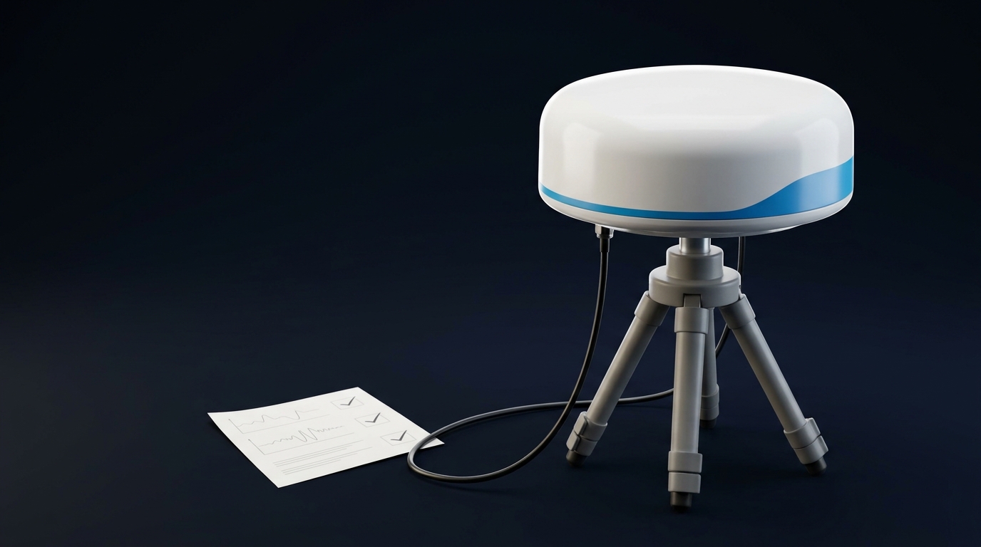
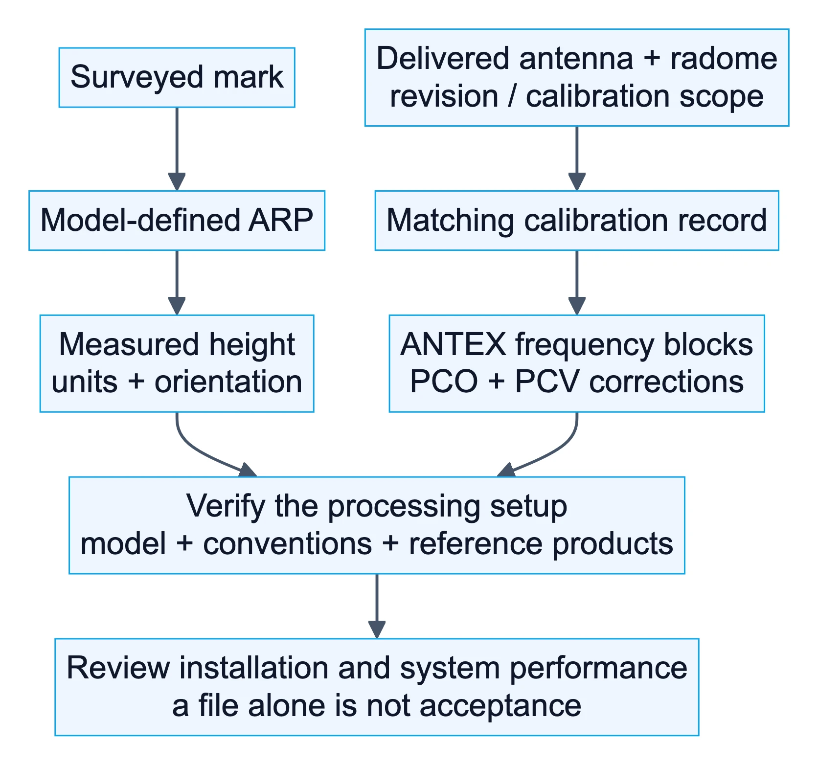
To check GNSS antenna calibration before buying, match the delivered antenna and radome to the calibration record, confirm the relevant frequency data, identify the physical reference point, and verify how your processing workflow will use the model. Having an ANTEX file is not the same as having suitable corrections applied to your observations.
For a survey-control, RTK base, CORS or monitoring project, the useful question is not simply “Is this antenna calibrated?” It is “Which record applies to this configuration, and who will verify that the project uses it correctly?”
ANTEX—the Antenna Exchange Format, commonly supplied as an .atx file—organizes antenna phase-center offsets and direction-dependent corrections. It does not certify the installed system, account for every local reflection, or guarantee a positioning result.
Before approving the purchase, close these four checks:
- Hardware match: the offered antenna and radome correspond to the record.
- Data match: the record has an appropriate calibration basis, scope and frequency coverage.
- Processing match: the receiver or processing software selects and applies the intended corrections.
- Installation match: the physical reference, measured height and configuration are documented.
If you are still choosing an antenna class, start with the broader high-precision GNSS antenna buyer’s guide. This guide focuses on the calibration evidence behind the purchase.
1. Match the antenna and radome to the calibration record
Begin with the product label and mechanical drawing, not a marketing name. Ask the supplier for the standardized antenna identifier, radome code, hardware revision and any mapping between the sales part number and the calibration identity.
The NGS antenna calibration database treats an antenna type as the antenna code together with its radome code. A record for the same antenna with a different cover is not automatically a match. NONE is a radome designation, not a statement that all covers are equivalent or that no calibration exists.
Record the scope as well. A type-mean calibration represents a model using measurements from sample units; a serial-specific calibration applies to the identified individual antenna. A purchase specification should say which evidence it requires. Neither scope, by itself, establishes the performance of your installed system.
Consider a hypothetical procurement mismatch: the quotation specifies an antenna with an additional weather cover, but the supplied record identifies the antenna without that cover. The buyer has received data, yet still lacks a documented match. The next action is to ask for the applicable record or a justified processing approach—not to rename the record to fit the quotation.
For an OEM version, require a written explanation of how the delivered revision relates to the calibrated configuration. Shared branding or a similar-looking enclosure is not evidence of equivalence.
2. Read the ANTEX header and frequency blocks
Open a copy of the file in a text editor and retain the original unchanged. Search for the exact antenna/radome identity, then inspect the complete antenna block. A combined file can contain satellite and ground-receiver antenna records; do not interpret a satellite record as your installed antenna model.
The IGS ANTEX 1.4 specification defines the fields below. This is a reading checklist, not a substitute for the format specification or your software’s import rules.
| Field or record | What to establish | Buyer’s follow-up |
|---|---|---|
TYPE / SERIAL NO |
Antenna/radome identity and individual-unit scope where specified | Does the record apply to the delivered unit? |
PCV TYPE / REFANT |
Absolute or relative correction basis | Is that basis appropriate for the planned processing? |
| Calibration provenance | Method, agency, sample information and date | Can the supplier explain the origin of these data? |
| Frequency blocks | Which constellation/frequency corrections are present | Do they cover the frequencies the processing needs? |
NORTH / EAST / UP |
Receiver antenna phase-center offset components, in millimeters | Are units and reference conventions handled correctly? |
DAZI and NOAZI |
Azimuth spacing and the azimuth-independent PCV pattern | Does the software support the supplied pattern? |
| Zenith grid | Angular range and sampling of the PCV data | Is the direction coverage appropriate? |
| Optional validity records | Applicability dates where supplied | Does the intended observation period fit? |
Check the correction basis, not just the extension
Absolute antenna calibration values and relative values use different reference conventions. In the header, A identifies absolute values and R relative values. “Absolute” is not an installed-system accuracy rating, nor does it identify the calibration method by itself. Review the provenance rather than assuming every absolute record was produced by a direct robotic measurement.
Compare frequency coverage with the processing plan
For GPS, G01, G02 and G05 identify L1, L2 and L5 frequency blocks. A receiver tracking L5, or an antenna datasheet listing L5 reception, does not establish that this ANTEX record contains the corresponding calibration data.
Make two separate lists: frequencies used by the project and corrections available in the record. Ask the processing owner to resolve any difference. Do not copy a missing frequency’s values from another band merely because the antenna receives both.
Read the angular grid correctly
For ground-receiver records, the grid uses zenith angle, not elevation: zenith angle is zero overhead. DAZI = 0 denotes a pattern without azimuth dependence; it does not mean that PCV is zero. The NOAZI pattern remains present even when additional azimuth-dependent rows exist.
Keep the download source, filename and retrieval date. If validity dates appear, check them; their absence alone does not invalidate a receiver antenna record because those fields are optional. File revision, record scope and project applicability are separate checks.
3. Keep ARP, phase-center corrections and antenna height separate
The antenna reference point, or ARP, is a defined physical point. The phase center offset, or PCO, locates a frequency-specific mean phase center relative to it. Phase center variation, or PCV, describes the remaining directional behavior. These are not three interchangeable ways of specifying antenna height.
The NGS calibration FAQ explains these distinctions and the north reference point, or NRP, used for orientation. Obtain the exact model’s drawing; do not assume the top of the radome or a convenient housing edge is the ARP.
Ask the installation team to retain:
- The drawing showing the ARP and orientation feature.
- The surveyed mark and the measurement path to the ARP.
- The height value, units, and whether the original measurement was vertical or slant.
- The orientation convention and installed configuration.
Do not add an ANTEX “up” offset manually to an entered height unless the software documentation explicitly requires that workflow. Otherwise, you risk counting a correction twice or supplying a height referenced to the wrong point.
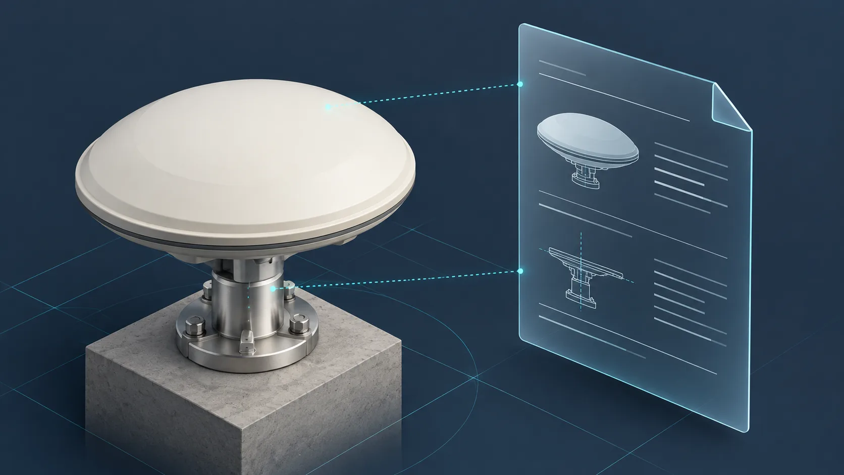
Configuration schematic, not calibration data or an installed-system acceptance result. The cover is an AI-generated conceptual illustration, not a specific GNSource product.
For the underlying directional behavior, see the explanation of phase center variation and RTK accuracy. For this procurement check, the deliverable is simpler: an unambiguous physical reference and a documented correction path.
4. Confirm what the processing software actually applies
Assign this check to the person responsible for the positioning workflow. A supplier can provide a file; only a review of the configured workflow can establish how that file is used.
Request evidence of the selected antenna/radome model, the source of its corrections and the handling of unavailable frequencies or unknown identifiers. Depending on the software, useful evidence may be a configuration export, processing report, model-match message or documented antenna-definition screen. The interface will vary, so do not make one software-specific screenshot a universal requirement.
Check the antenna identity in observation metadata as well, including RINEX headers where applicable. Correct values in a downloaded file do not resolve an incorrect identifier in the observations.
Reference-product compatibility also matters. The IGS antenna working group emphasizes consistent antenna modeling and standardized metadata. Receiver-antenna corrections, satellite-antenna models, precise products and reference-frame conventions must be considered together by the processing owner. Choosing the newest file by date alone is not a compatibility check.
For post-processed work, retain the selected model and product versions with the processing record. For real-time work, ask the receiver or service provider which antenna model is supported and where corrections are handled. Do not assume a desktop ANTEX import changes a rover’s firmware or a network service’s configuration.
The acceptance question is specific: “Can we show which applicable corrections this workflow used?” Successful import is only one step toward answering it.
5. Resolve missing records before releasing the order
If the exact configuration is absent from a public database, first ask whether the supplier has an applicable independent calibration and whether your software can use it. A missing public listing is not proof that the hardware is defective, but it leaves the public-record check unresolved.
Use the missing evidence to define the next action:
- Different radome or revision: obtain applicability evidence or review the changed configuration.
- Required frequency absent: ask the processing owner for an acceptable, documented approach.
- Unclear calibration origin: request the original source and scope rather than relying on a renamed file.
Do not substitute a nearby model silently. If a project permits a fallback, retain who approved it, why it was acceptable and how its limitations will be evaluated.
RF characteristics such as gain, axial ratio and noise figure remain useful, but they do not answer these record-matching questions. The companion guide to reading a GNSS antenna test report covers that different evidence set.
6. Request a calibration handover package
Send the supplier a request that identifies the project, rather than asking only for “a calibration certificate.” For example:
For our civil surveying/reference-station project, please provide the exact antenna and radome identifiers, delivered hardware revision, and the applicable GNSS antenna calibration file with its source and revision. State whether the record is type-mean or serial-specific, identify its frequency coverage and calibration basis, and include the ARP/NRP drawing. Please explain any difference between the quoted configuration and the calibration record. We will confirm software compatibility and installed-system acceptance separately with our processing team.
Keep the response with the purchase record. At commissioning, add the delivered label/serial photograph, actual mount and radome configuration, measured reference geometry, receiver/software details and processing evidence. Record cable, connectors and power arrangements as integration context; they are not additional standard ANTEX antenna identifiers.
Then define what happens when the configuration changes:
| Change | Evidence to revisit | Responsible owner |
|---|---|---|
| Antenna replacement | Delivered identity, record scope and reference geometry | Procurement and survey lead |
| Radome, enclosure or mount modification | Calibration applicability and nearby structural effects | Antenna supplier and integration lead |
| Processing-model or product update | Compatibility, selected corrections and comparison baseline | Processing lead |
| Cable, receiver or power-path change | RF-path compatibility and operational checks | Integration lead |
Nearby structures can affect antenna behavior, so an unchanged product label is not sufficient evidence that every installation change is harmless. Equally, not every cable change automatically requires a new antenna calibration. Review the affected part of the measurement chain and define the necessary revalidation.
When comparing GNSource high-precision measurement antennas, include your receiver, required frequencies, processing workflow and calibration requirements in the inquiry. Ask about evidence for the specific configuration; do not assume every catalog option has the same calibration package.
FAQ
Does every RTK antenna need an individual calibration?
No universal requirement follows from the term RTK alone. The project’s measurement requirements, network rules and processing method determine the necessary evidence. Confirm whether a type-mean model is acceptable or whether the individual unit needs calibration.
Is an ANTEX file the same as a calibration certificate?
No. ANTEX is an exchange format for correction data and related metadata. A certificate or report may document the calibration work and its scope. Check that both refer to the supplied configuration; neither automatically constitutes installed-system acceptance.
Can I use a similar antenna’s calibration if mine is not listed?
Do not treat similarity as equivalence. Ask for an applicable record or an explicitly approved project approach. Record the remaining uncertainty rather than disguising a substitute as an exact match.
Can an OEM cover keep the original antenna calibration?
Not by assumption. Ask the supplier to review the modified configuration and provide evidence of applicability. Keep that question separate from whether the enclosure meets the project’s mechanical or environmental requirements.