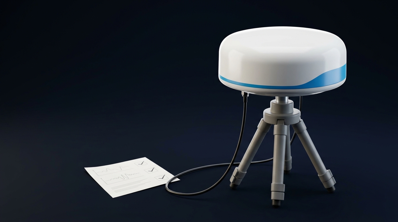
A GNSS antenna test report is useful only when it states what was tested, how it was configured, and which decision the result supports. For a high-precision project, read it in layers: confirm the RF chain is functional, check the installed system under comparable conditions, then verify whether the phase-centre evidence is appropriate for the required accuracy. One attractive gain or C/N0 number cannot prove all three.
That distinction matters when the antenna will support an RTK rover, survey-control point, reference station, deformation-monitoring installation, or timing system. A report may show that an antenna receives the required bands. It may not show that the supplied cable, mount, radome, nearby reflectors, or processing model will preserve repeatable position results after installation.
First, identify what the report actually tested
Before comparing values, identify the class of evidence. Many supplier documents use the word “test” for very different activities.
| Evidence type | What it can answer | What it cannot answer by itself |
|---|---|---|
| Component or RF functional test | Whether the specified antenna, LNA, connector, and measurement setup produced the stated response | Whether the installed system has a clear sky view, a healthy cable run, or suitable phase-centre behaviour |
| Installed-system acceptance test | Whether the actual antenna, cable, receiver, power feed, and mounting arrangement behave consistently at the site | Whether a different site or a different mechanical configuration will behave the same way |
| Geodetic calibration | How an antenna model’s reference point and direction-dependent phase response are characterized for measurement processing | Whether the delivered installation has damaged connectors, incorrect bias power, or unsuitable siting |
The first question is therefore not “Is this value good?” It is “Does this report test the same object and condition that matter to my project?” A buyer choosing an RTK or reference-station antenna should also start with the wider selection context in our high-precision GNSS antenna buyer’s guide.
Ask the supplier to identify the model, hardware revision, antenna configuration, frequency range, cable or fixture, power state, test location, and report date. If a result has no stated conditions, treat it as a product characteristic to investigate—not as acceptance evidence for your installation.
Read RF results as a method, not a headline number
A useful GNSS antenna test procedure makes its method visible. The report should let an engineer tell whether the result belongs to the radiating element, the active electronics, or the complete receive path.
Start with the signal plan. Confirm that the stated bands match the receiver and correction workflow you intend to use. “Multi-band” is not a test condition; the report should show which GNSS bands were measured and whether performance is presented across each band or only at selected points. If an antenna is active, record the DC bias conditions and the cable or fixture used during the measurement. Those details affect what the receiver sees.
Then read the RF figures together, not in isolation:
| Report item | Why it matters | Question to ask before using it in a purchase decision |
|---|---|---|
| Frequency coverage or response | Confirms that the tested path addresses the bands required by the system | Which bands, bandwidths, and tolerances were actually measured? |
| Element gain and radiation pattern | Shows where the antenna is most sensitive and whether low-elevation coverage was characterized | Is the result by frequency and angle, or only a single peak figure? |
| Axial ratio or polarization information | Helps evaluate how the antenna handles the circularly polarized GNSS signal and reflected energy | At which elevation angles and frequencies was it measured? |
| LNA gain and noise figure | Matters for an active antenna’s receive chain and cable-loss budget | Are LNA gain, noise figure, bias voltage, and test temperature separately stated? |
| Reference or comparison setup | Gives context for repeatability and interpretation | Was a known reference configuration used, and were the conditions comparable? |
Do not turn a vendor’s reported receiver observable into a universal acceptance limit. C/N0, AGC behavior, and tracking results depend on the receiver, firmware, bands in use, sky conditions, cable loss, and installation. A practical vendor example can be useful for understanding what a documented test setup looks like, but the configuration-specific observations in the Fixposition GNSS antenna testing note should not be copied as a universal pass/fail number.
The same caution applies to gain. A high figure may combine the antenna element and an integrated amplifier, while a low figure may describe only one part of the system. Ask for the definition, units, frequency, angle, and measurement configuration before comparing two reports.
Separate a healthy RF chain from a calibrated antenna
This is the most important boundary in a GNSS antenna test report.
An RF or open-sky functional check can help establish that the active antenna is powered, the cable path is intact, the receiver tracks the expected signals, and the installation does not show an obvious fault. It does not establish the phase-centre model needed for a measurement application.
For that decision, look for calibration evidence that identifies the antenna reference point (ARP), phase centre offset (PCO), and phase centre variation (PCV). The NOAA National Geodetic Survey’s GNSS antenna calibration overview explains why these direction-dependent effects matter in precise positioning. The International GNSS Service Antenna Working Group is also a useful place to understand the role of antenna models and metadata in high-accuracy GNSS work.
In buying terms, the distinction is simple:
- A working RF path does not prove that the antenna’s phase response is suitable for a CORS station or a repeatability-critical survey workflow.
- A published calibration model does not prove that the delivered cable, bias supply, connector sealing, or mounting surface is healthy.
For RTK and survey work, calibration relevance depends on the processing approach and accuracy requirement. For permanent or measurement-sensitive sites, confirm that the exact antenna configuration—including any radome where applicable—can be matched to the required model and documentation. Our article on how PCV affects RTK accuracy explains why a direction-dependent phase effect cannot be reduced to one generic “phase-centre accuracy” number.
Use the installed system to isolate faults in the right order
If an installed system underperforms, do not begin by assuming the antenna element is defective. Test from the receiver outward and keep every comparison condition as similar as practical.
-
Confirm the intended configuration. Record the receiver model and firmware, enabled bands, antenna model, active or passive status, DC-bias requirement, cable type and length, connectors, mounting surface, and nearby structures. This is the baseline you need before any reading can be interpreted.
-
Verify power and the RF path. For an active antenna, confirm that the receiver or bias arrangement is appropriate for the antenna’s stated requirements. Inspect connector engagement, cable damage, water ingress, strain relief, and unnecessary adapters. A measurement at the receiver input can describe the path only when performed with suitable equipment and procedures for that active design.
-
Compare with a known-good configuration where practical. A controlled swap—using a known-good antenna or a known-good cable path—can narrow the fault domain. Change one factor at a time, keep the receiver settings unchanged, and document the sky and mounting conditions. This is more informative than comparing observations taken on different days at different sites.
-
Review receiver observables over comparable conditions. Look for repeatable changes in tracked bands, lock continuity, receiver diagnostics, and signal observations across similar satellite geometry. Treat them as trend evidence, not as a standalone calibration result.
-
Inspect the installation before replacing hardware. A clear view of the sky, reasonable separation from reflective surfaces, a stable mount, cable routing, and radome compatibility can alter the received result. If the installation is permanent, retain photographs and dimensions with the acceptance record. The CORS GNSS antenna selection checklist provides a separate, permanent-station-focused review of those site dependencies. For reflective-site diagnosis, use these multipath checks for a geodetic reference station before treating a single receiver observation as an antenna fault.
-
Escalate the right uncertainty. If the RF path is sound but repeatability remains insufficient, the next question may be calibration suitability, processing configuration, or site multipath—not another arbitrary gain test. State the unresolved condition and involve the receiver, processing, or antenna engineering owner as appropriate.
This order prevents a common mistake: using a single bench reading to diagnose a problem that belongs to installation geometry, or using a calibration document to explain a cable or power fault.
Match the evidence to the consequence of being wrong
The needed report depth changes with the deployment. A short incoming check may be enough for one portable application but insufficient for a permanent station.
| Civilian use case | Minimum useful evidence | What to add before accepting the system |
|---|---|---|
| RTK rover | Band compatibility, active/passive and bias compatibility, cable/connector inspection, comparable open-sky receiver observations | Mounting and ground-plane context; a controlled comparison if the integration is new |
| Survey control or static survey | The rover evidence above plus traceable antenna identity and a documented setup | A processing-compatible antenna model where the measurement method and required repeatability call for it |
| CORS or reference station | Traceable antenna/radome configuration, installation record, RF-path verification, long-duration operational observations | Calibration/model compatibility, stable monument and site review, plus a commissioning and change-control record |
| Deformation monitoring | Traceable configuration, stable power/RF path, repeatable observations over the relevant time window | A documented baseline and a revalidation trigger for antenna, cable, radome, or mounting changes |
| Timing installation | Supported signal plan, power and cable-path verification, installation record | Receiver-system validation under the timing architecture and a documented change-control process |
The table is deliberately not a list of universal thresholds. The useful acceptance condition is the one that links the exact antenna configuration to the risk of the intended measurement. A one-day receiver check may establish basic health; it should not be presented as proof of multi-year stability at a permanent installation.
Turn the report into an RFQ and acceptance checklist
Before release, ask the supplier or integration team for a report package that answers these questions plainly:
- What exact antenna model, hardware revision, serial or traceable batch, and radome configuration were tested?
- Which GNSS bands were measured, and which test method, fixture, cable, power condition, and environment were used?
- Are element gain, pattern, axial ratio, LNA gain, and noise figures clearly labeled by frequency and condition where relevant?
- Does the document distinguish a component test from an installed-system acceptance check?
- For a measurement-sensitive application, what calibration or processing-model evidence is available for the exact configuration?
- Which receiver settings and observables will be recorded during commissioning, and what comparable baseline will be retained?
- What installation details—mount, cable route, connectors, power feed, radome, and nearby reflectors—must remain unchanged after acceptance?
- What changes require re-test, revalidation, or a review of the processing model?
If a report cannot answer most of these questions, it is not necessarily wrong. It may simply be a product-characterization document rather than the acceptance evidence your project needs. In that case, define the missing test and its conditions before issuing a purchase approval.
For a high-precision civilian GNSS project, you can use this checklist alongside the relevant high-precision measurement antenna options and send an inquiry with the receiver, required bands, installation drawing, and report you want reviewed.
FAQ
How do I test whether a GNSS antenna is working?
Start by confirming the installed configuration: antenna type, supported bands, power/bias arrangement, cable and connectors, receiver settings, and mounting. For an active antenna, check the powered RF path with methods appropriate to that design, then compare receiver observations under similar conditions or against a known-good configuration. A functional check establishes health; it does not automatically establish calibration suitability for precision measurement.
Is VSWR alone enough to test an active GNSS antenna?
No. An active GNSS antenna includes electronics and a powered receive path, so a single passive-style VSWR reading does not describe the complete system behavior. Use a method appropriate to the antenna design and document the bias state, cable/fixture, frequency range, and receiver context. Escalate ambiguous results to the antenna or RF engineering owner.
Do I need calibration evidence before buying an RTK or CORS antenna?
It depends on the required accuracy, processing method, and whether the installation is portable or permanent. Calibration-related evidence becomes more important when phase-centre behavior and repeatability affect the deliverable, especially for reference stations and long-term measurement. Match the exact antenna configuration to the processing requirement rather than assuming that a generic RF test replaces calibration.
![How to Set Up an RTK Base Station Antenna [2026 Guide]](/blog/_assets/upload/aaacdd5rjxygrxhc/2026/06/17/image_1781704508-i4v1t4p5.jpeg)