Choose GNSS antenna LNA gain so the entire gain range seen at the receiver input stays within the receiver’s specified limits on every required band. Check minimum gain with maximum feedline loss, then maximum gain with minimum feedline loss. Evaluate noise figure separately, with the loss stages in their actual order.
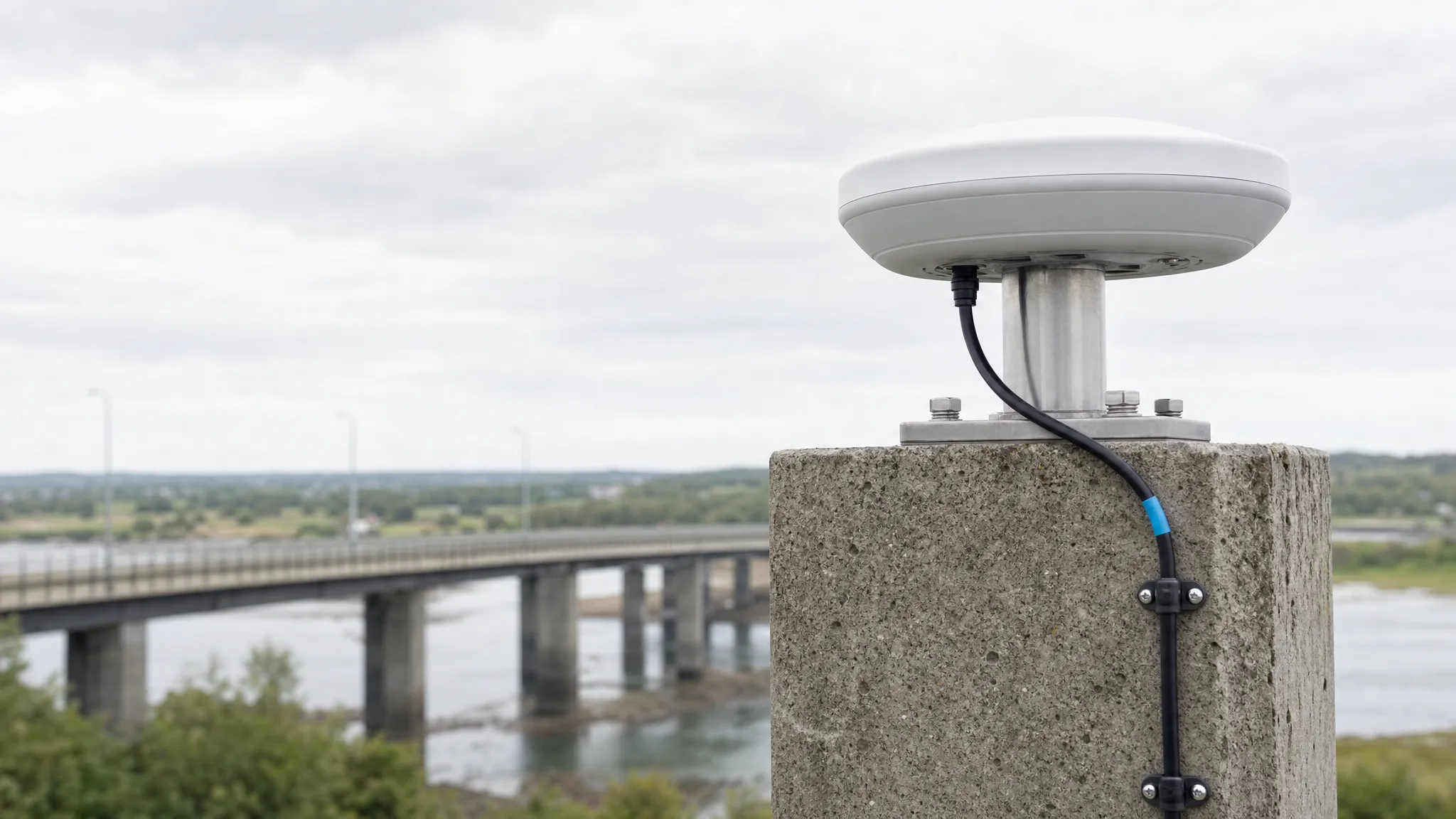
A survey receiver may ship with a short cable on a mobile unit and a long cable at a fixed station. A single antenna can look suitable on both nominal calculations while falling outside the specified range at either end. The useful purchasing decision is which antenna and cable combinations can share a bill of materials.
1. Find the receiver limits for GNSS antenna LNA gain
Start with the receiver model, firmware, input port and operating mode. Record the lower and upper limits at the relevant reference plane, usually the receiver’s RF input for a cascaded gain specification. If the manual also lists a recommended range, keep that design target visible alongside the supported limits.
NovAtel’s OEM7 application note, for example, gives different supported gain ranges depending on the firmware version. It also identifies a different minimum when its high dynamic range mode is enabled. Confirm the setting for the receiver that will ship. NovAtel APN-077 on RF equipment selection
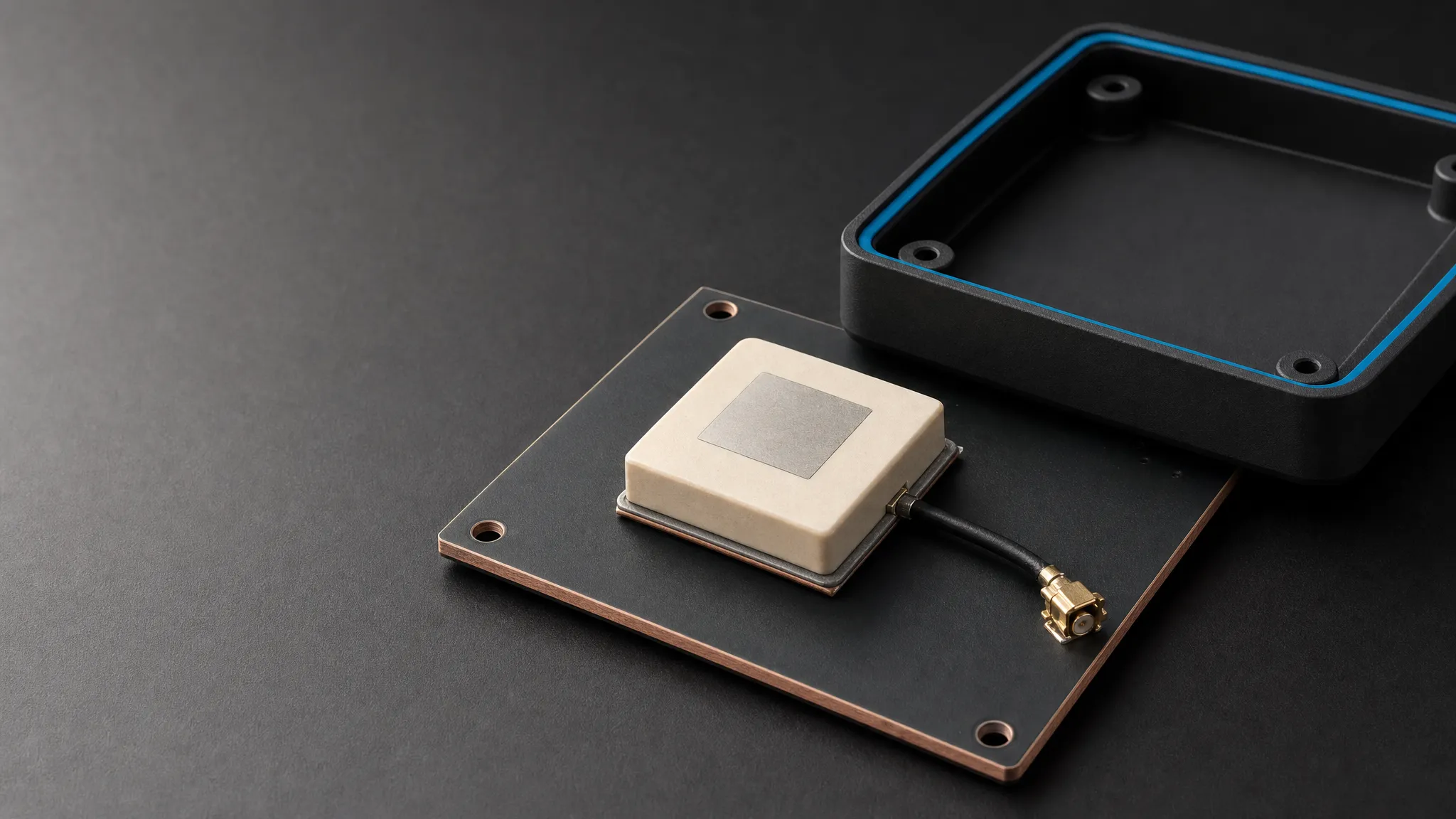
Check which gain quantity the manual specifies. The u-blox ZED-F20P integration manual includes passive losses such as cables and filters in its active-antenna gain recommendations and lists radiator gain separately in dBic. Ask the antenna supplier for the active section’s gain range, the radiator’s gain and pattern, and the connector or test points at which the values apply. An amplifier gain in dB describes electronic amplification. A radiator gain in dBi or dBic describes directional response against its stated reference. u-blox ZED-F20P Integration Manual, § 4.4
Record the maximum RF input power separately if the receiver specifies it. That is a power limit, generally in dBm, distinct from the gain budget in dB.
2. Calculate the lowest and highest gain for each cable option
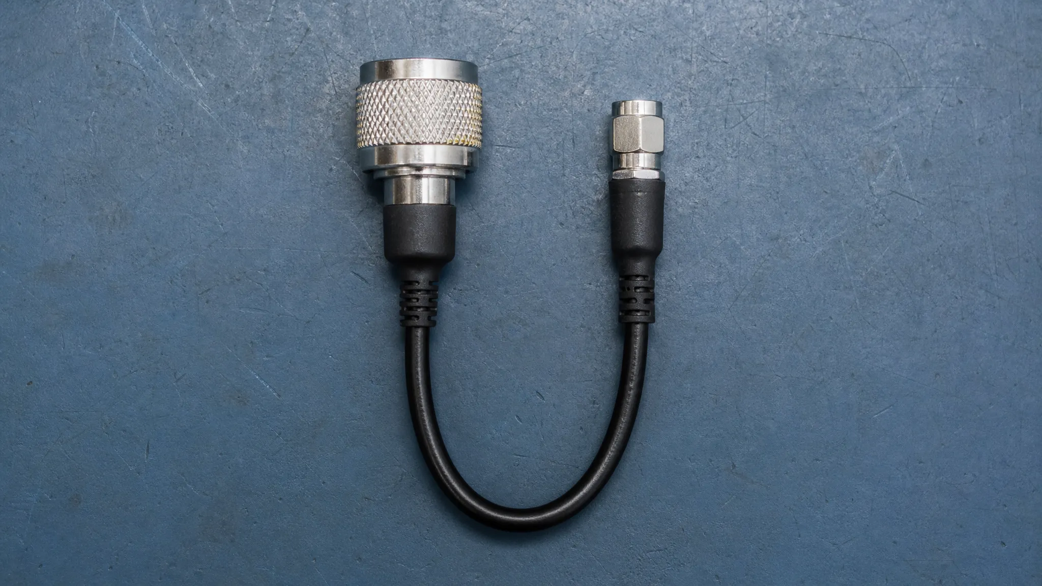
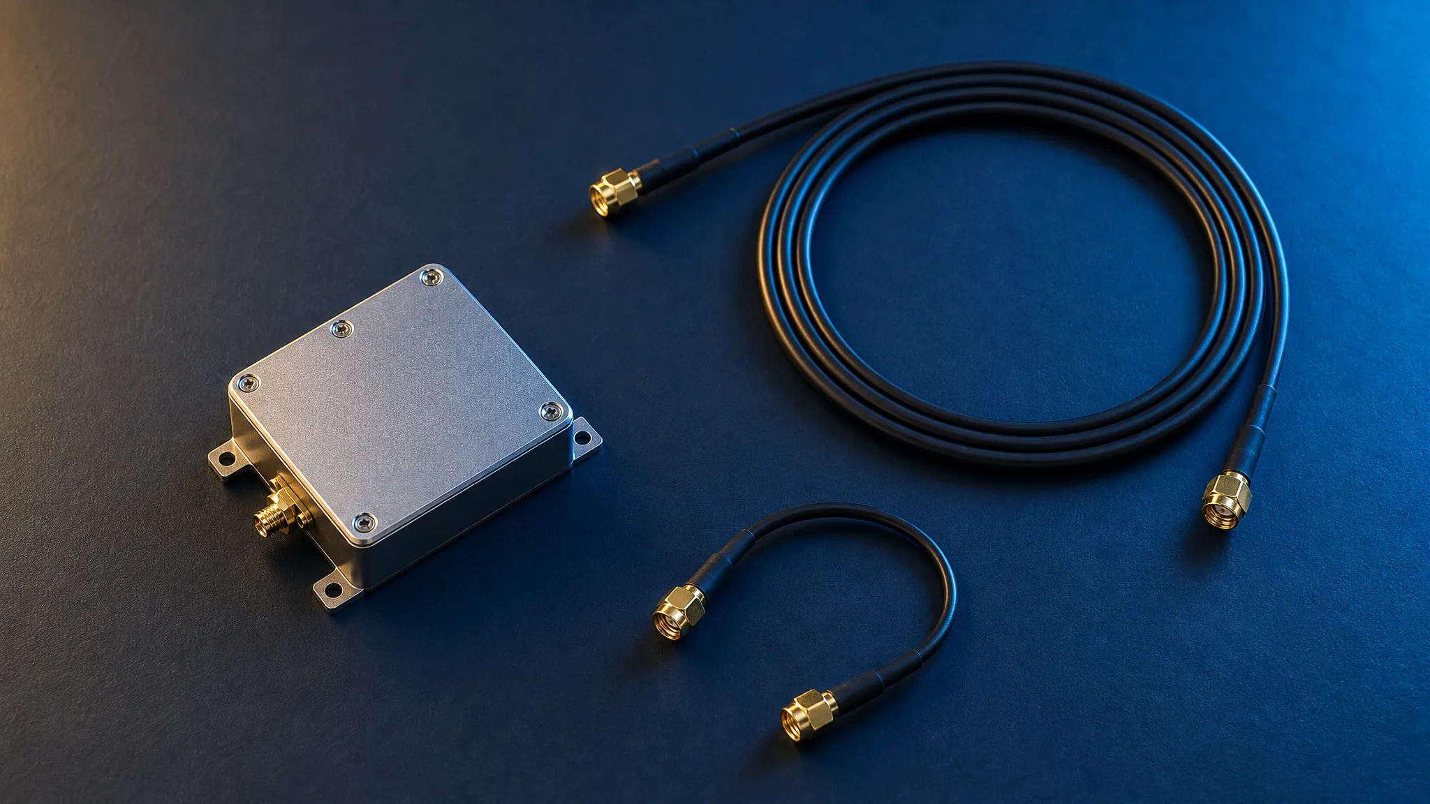
When the output connector is the reference plane for the antenna’s electronic gain, subtract the losses between that connector and the receiver. Include inline gain or loss in that path. If the antenna specification already includes a factory cable, subtract only losses beyond the stated output reference plane. If it provides bare LNA gain, ask for the losses of the intervening components or a measured gain range for the complete active section.
Use a separate row for each required band and each assembly option. An insertion-loss value measured near GPS L1 may differ from the value on L2 or L5. Obtain limits for the cable and inline components over the relevant frequencies, and check the antenna gain limits at the specified bias and temperature. Use the finished assembly’s loss data where available.
For the simple case with an antenna amplifier followed only by losses:
Lowest net gain = minimum active-section gain − maximum downstream loss.
Highest net gain = maximum active-section gain − minimum downstream loss.
Suppose a project has a hypothetical 21–36 dB receiver window at the band being checked. Its short cable assembly has 1–3 dB of total downstream loss and its long assembly has 7–13 dB. The antenna candidates have nominal active-section gains of 31 dB and 37 dB, each with a ±2 dB tolerance.
| Candidate | Short assembly | Long assembly |
|---|---|---|
| A, 29–33 dB | 26–32 dB, inside | 16–26 dB, can fall below the minimum |
| B, 35–39 dB | 32–38 dB, can exceed the maximum | 22–32 dB, inside |
At the midpoint losses of 2 and 10 dB, both nominal candidates would appear to fit both routes. Candidate A gives 29 and 21 dB. Candidate B gives 35 and 27 dB. The range calculation shows what those four numbers miss.
If one antenna must serve both routes, work backward. It needs at least 34 dB at its lowest gain to meet the 21 dB receiver minimum after 13 dB of loss. It also needs no more than 37 dB at its highest gain to respect the 36 dB maximum after 1 dB of loss. Those bounds allow a 3 dB spread. A candidate with a guaranteed ±2 dB tolerance spans 4 dB, so that tolerance cannot fit both limits. Options include a tighter gain tolerance, a lower-loss long assembly or separate qualified configurations. Recalculate across the other bands before choosing.
3. Compare noise figure with the components in order
The gain calculation gives the signal level change through the chain. Noise figure describes how much the chain degrades the signal-to-noise ratio under its specified measurement conditions. An early amplifier with low noise figure and adequate gain reduces the contribution of noise from later stages. A loss before that amplifier degrades the signal-to-noise ratio reaching it. Analog Devices’ explanation of cascaded noise figure
Consider one 20 dB amplifier with a 1 dB noise figure and one 2 dB lossy section. The following theoretical example uses matched stages and treats the passive section as being at the standard reference temperature of 290 K. It excludes the receiver and antenna environment.
| Stage order | Total gain | Cascaded noise figure of these two stages |
|---|---|---|
| Amplifier, then lossy section | 18 dB | About 1.02 dB |
| Lossy section, then amplifier | 18 dB | 3.00 dB |
The cascade calculation uses linear noise factors and gains. The early amplifier makes the same loss less consequential to the two-stage noise figure, even though the loss still reduces the level reaching the receiver. Ask the supplier where filters, traces and connectors sit relative to the first low-noise amplifier, especially if a drawing labels the amplifier module separately from the radiator.
Carrier-to-noise-density ratio, written C/N₀ and reported by receivers in dB-Hz, is a tracking measurement that can vary with the signal, installation and receiver. If you want to explore a theoretical sensitivity case, use the GNSource link-budget calculator for its GPS L1 model. Use frequency-specific vendor data and installed measurements to assess a multiband design.
4. Turn the budget into a sample acceptance check
Before placing the production order, agree on the exact antenna revision, cable construction and any inline hardware for each build. Ask the supplier for gain and noise figure over the bands you require, including whether quoted values are typical or guaranteed limits. Record the bias and test conditions used. The guide to reading a GNSS antenna test report explains what to look for in the evidence.
For each sample configuration, retain three records:
- Gain and loss. Keep the antenna and cable evidence used for the minimum and maximum calculation, with the exact parts and measurement reference planes.
- Bias under load. Check the voltage at the antenna and the current available through the installed path. Review the DC behavior of inline parts. The active and passive GNSS antenna guide explains the different power arrangements.
- Receiver observation. Log signal tracking and C/N₀ by band with the intended firmware, mount and operating conditions. Hold the test setup as consistent as practical when comparing candidate assemblies, and agree on acceptance criteria before testing.
Record gain as a separate design criterion when reviewing the installed samples. Sample acceptance also depends on the RF and installation criteria defined for the project.
FAQ
Is a 40 dB GNSS antenna LNA better than a 30 dB LNA?
Compare the two assemblies against the receiver’s gain limits and required bands. Extra gain can help meet the lower limit with a long feedline. A shorter, lower-loss feedline can leave the same design above the upper limit. Noise figure and filtering need their own checks.
How much cable loss can an active GNSS antenna tolerate?
For the gain calculation, subtract the receiver’s required minimum from the antenna’s minimum active gain at the band of interest, after accounting for any other inline components. Verify the upper gain limit, bias delivery and noise budget as separate conditions before choosing a physical cable length.
Can I solve a noise problem by adding an amplifier next to the receiver?
A receiver-side amplifier can raise the level entering the receiver. Its effect on noise depends on the preceding stages. When the feedline is ahead of the first amplifier, check that early loss before choosing additional gain.
For a project with more than one cable route, share the receiver model, required bands, bias supply and cable options when you request a configuration review. Include the receiver’s gain limits if they are already defined.