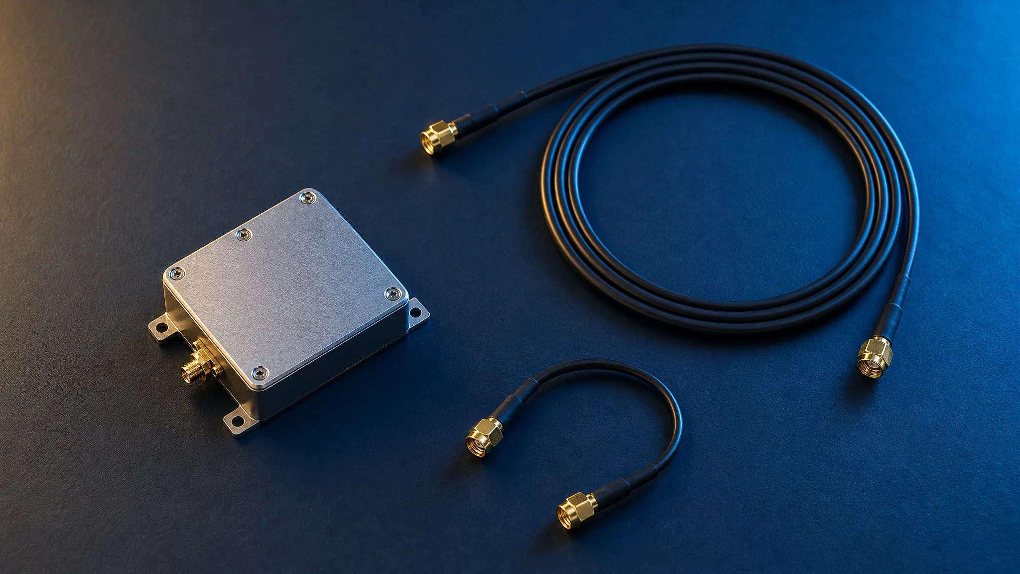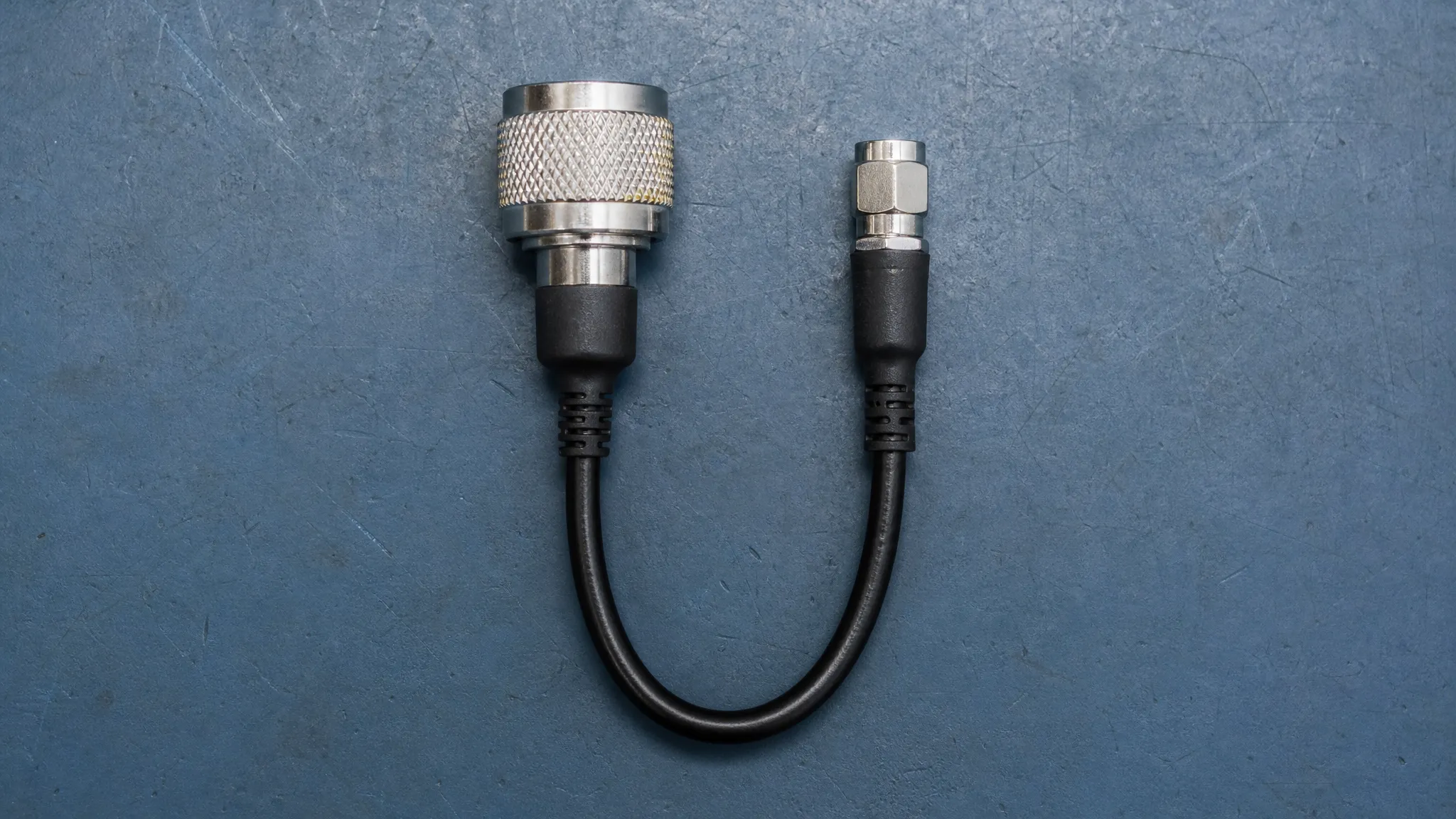
To order a TNC to SMA GNSS antenna cable, identify the mating connector at each port, set the maximum loss across the GNSS bands you use, and check whether the cable path must carry DC power to the antenna. If any part of the cable goes outdoors, specify where and how it will be exposed. Ask the vendor to put all four requirements on the assembly drawing or quote.
A survey antenna can have a TNC jack while the receiver enclosure has an SMA jack. “TNC to SMA” tells the supplier which connector families are involved. The order still needs the exact ends, cable length and performance limits.
1. Match both ports before ordering a TNC to SMA GNSS antenna cable
Start with the exact antenna and receiver models, including suffixes. Check the drawings for both ports. TNC and SMA both use threaded coupling, with TNC typically larger. The connector at each end of the cable must match the family, mating style, polarity and nominal impedance shown in the corresponding equipment documentation.
For example, NovAtel lists a 50 Ω TNC female antenna port on the PwrPak7 and a 50 Ω SMA female antenna port on the PwrPak7D. Those are two devices in the same family, with different cable ends at the receiver. NovAtel PwrPak7 electrical and environmental specifications
| Confirmed equipment port | Matching cable end for these examples |
|---|---|
| Standard TNC jack, with a center socket | Standard TNC plug, with a center pin |
| Standard SMA jack, with a center socket | Standard SMA plug, with a center pin |
| RP-SMA jack, with a center pin | RP-SMA plug, with a center socket |
Match the shell and the center contact together. A standard SMA plug and an RP-SMA jack can have compatible threads and two opposing center pins. The same standard-versus-reverse distinction applies to TNC. When checking a device photo, use an end-on view in good light and confirm what you see against the drawing. Campbell Scientific’s RF connector identification guide, GNSource’s SMA and RP-SMA connector guide
Record the equipment port and the mating cable end as separate fields. For a confirmed standard TNC jack on the antenna and standard SMA jack on the receiver, the connector portion of the order reads:
Antenna end: standard TNC plug, center pin. Receiver end: standard SMA plug, center pin. Assembly impedance: 50 Ω for this 50 Ω system.
2. Choose the cable construction for the installation
Measure along the installed route. Check the cable maker’s minimum bend radius and leave room for service slack. Mark the drawing with the length reference points and tolerance. Where space is tight, ask for a dimensioned drawing of the straight or right-angle connector that will actually ship. A right-angle body still needs room for its coupling and for supporting the cable.
An assembly terminated with the correct connector at each end keeps the parts list short and avoids an extra mated interface. A separate jumper can make sense when a receiver is routinely removed or when a thick outdoor cable would load a small port. In that case, include the jumper and each transition in the drawing and loss budget. Support the heavier cable before it reaches the receiver.
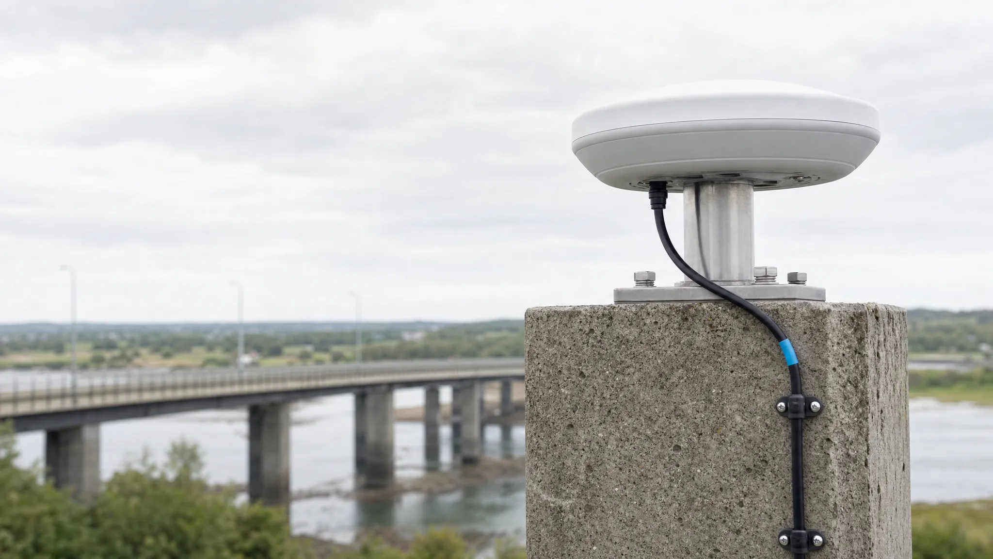
Check the exact assembly’s suitability for the environment. For permanent outdoor use, specify jacket exposure, connector sealing in the mated condition, and weatherproofing at the enclosure entry. NovAtel, for instance, advises against permanent outdoor use for two specific SMA-to-TNC assemblies it lists. Ask the cable supplier which construction it recommends for your route. NovAtel’s OEM7 coaxial cable selection guide
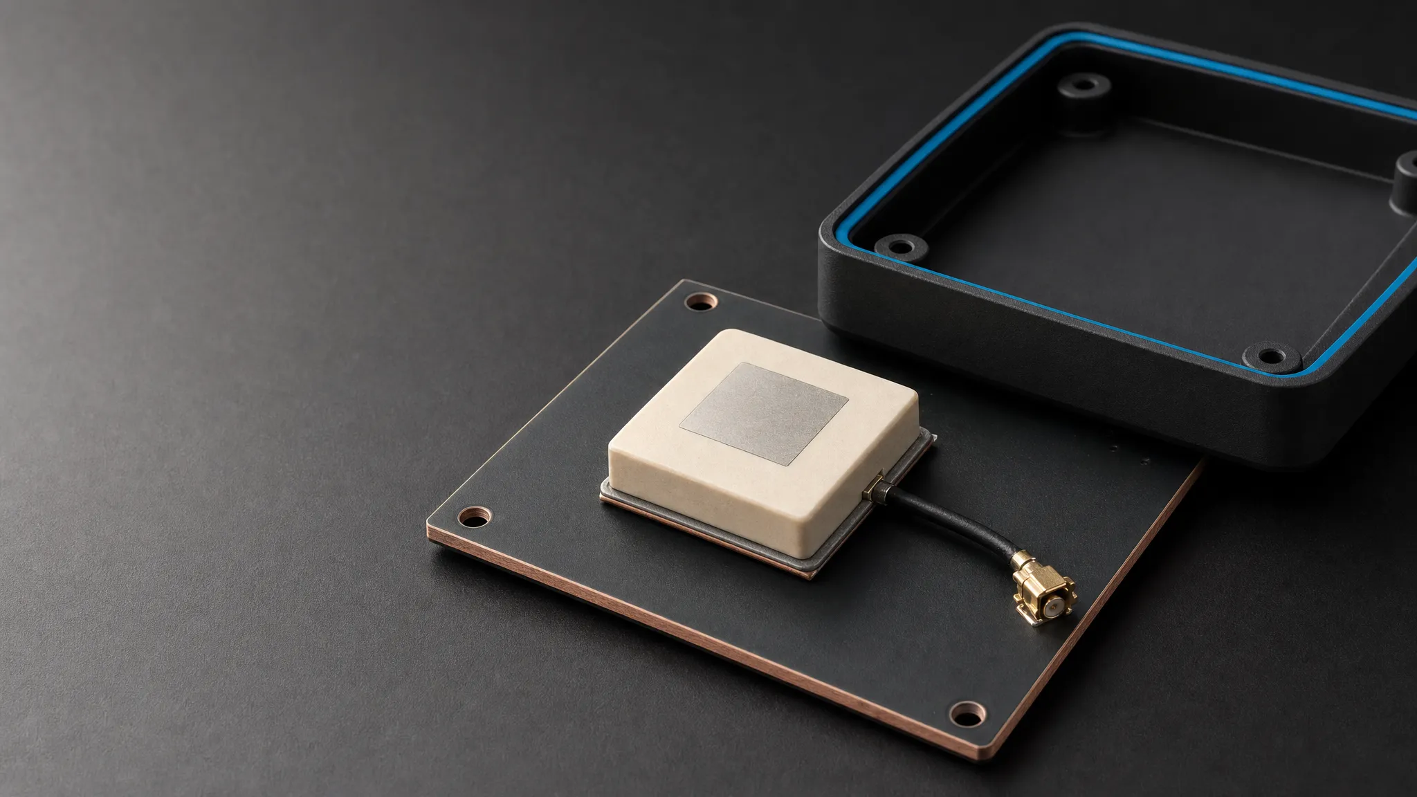
If you are still verifying the antenna end, the external TDXL-BA720 lists TNC-K and the embedded TDXL-BA730 lists MCX. Ask for the matching interface drawing for the selected configuration. For MCX, confirm the plug or jack, mounting orientation and available clearance. Some receiver cards use the smaller MMCX or another family, so include the board revision and part drawing when ordering a pigtail. NovAtel’s common RF connector reference
3. Set the RF loss budget and confirm the DC path
Give the supplier the frequencies or bands your system needs. For a system that uses GPS L1, L2 and L5, request loss over all three bands for the quoted length. Specify the maximum insertion loss for the assembled cable, including its terminations. If your receiver or system design also specifies return loss or VSWR, put the relevant limits and frequency range on the drawing.
Add any separately fitted jumper, adapter or surge protector to the RF budget. Count each item once. For an active antenna, subtract the downstream RF losses from the active electronics gain in dB, using the reference planes in the receiver documentation. If the specified gain already includes a factory cable, count only the losses beyond its output. Compare the result with the permitted input range for the receiver and firmware. NovAtel documents different input limits by firmware and reports different cable losses at GPS L1 and L2 for the same assemblies. Use the values for your own receiver and cable. NovAtel APN-077 on RF equipment selection
If the receiver powers the antenna through the coax, check its available current and the voltage that reaches the antenna under load. Include voltage drop along the center conductor and return path, and confirm where DC can pass through any inline equipment. A component may pass GNSS RF while blocking DC. Verify the specified behavior of each surge protector, splitter, attenuator or DC block before ordering.
If an external bias tee is required, document which port feeds power toward the antenna and how the receiver input is isolated from that supply. Use the receiver maker’s instructions for the internal bias setting. For passive antennas, follow those instructions for disabling or blocking bias where required. NovAtel’s external bias supply example, GNSource’s active and passive GNSS antenna guide
4. Put the requirements on the quote and approve a sample
Send these details with the request for quotation. Ask the supplier to flag substitutions before the sample is built.
| RFQ field | What to give the cable supplier |
|---|---|
| Equipment and both ends | Exact antenna and receiver model or drawing revision. For each cable end, give the family, plug or jack, polarity, contact and exit angle. |
| Cable and length | Nominal impedance, routed length, measurement reference points and tolerance. Include cable support and bend clearance. |
| RF performance | Required frequencies and maximum insertion loss for the completed assembly. Add return loss or VSWR criteria where specified. |
| DC behavior | Bias source, antenna voltage and current requirements, and which inline components must pass or block DC. |
| Environment | Indoor or outdoor sections, exposure at each connection, jacket requirements and any mated sealing requirements. |
| Sample evidence | Dimensioned drawing, cable and connector part numbers, and test results against the agreed RF and DC criteria. |
For the first sample, inspect the connector ends and fit the cable with power off. Verify clearance in the intended enclosure or mount. Review the insertion loss results against the agreed bands and, for an active installation, check antenna power under load using an appropriate test fixture. A continuity check can help catch a wiring fault. The RF test report establishes loss over the specified frequency range.
Record the cable type, connector part numbers and approved drawing revision so later orders refer to the same construction.
FAQ
What cable connects a female TNC antenna port to a female SMA receiver port?
For standard-polarity ports, use a standard TNC male plug at the antenna and a standard SMA male plug at the receiver. Both cable ends have a center pin in this example. Match the cable impedance to the equipment and check the RF loss and DC requirements before ordering.
Can I use an SMA-to-TNC adapter with an existing cable?
Yes, if the adapter mates correctly, meets the RF and DC requirements and can be supported in the installation. Include its loss in the budget, and confirm the suitability of the additional mated connection for the environment.
Does an outdoor antenna make its TNC-to-SMA cable suitable for permanent outdoor use?
Check the cable, connector and mated assembly specifications for the expected exposure. Confirm the jacket, seal and enclosure entry independently of the antenna housing rating.
Can an MCX plug replace an MMCX plug on a receiver board?
MCX and MMCX are different connector families with different mating interfaces. Use the receiver board’s part number and drawing to identify the mating plug before requesting a replacement pigtail.
If you are selecting a GNSS antenna as well as the cable, use the GNSource antenna selector to organize your signal, mounting and antenna requirements. Keep the receiver model and the proposed cable route with the project brief.