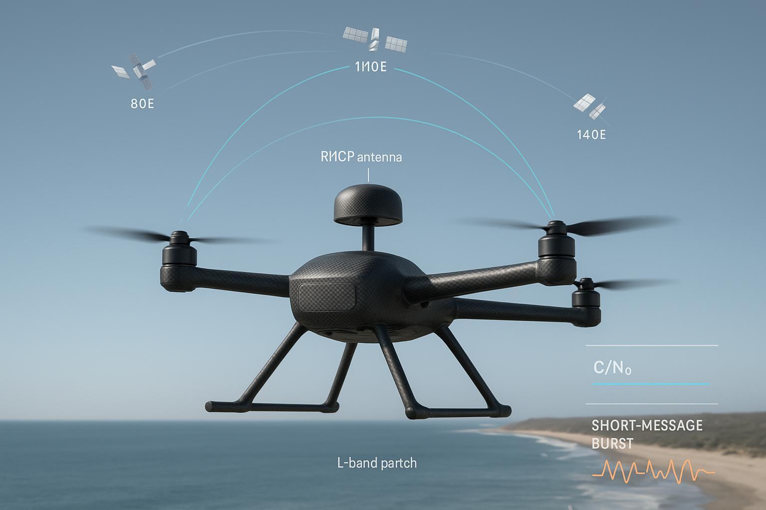
I first ran into the “RDSS vs RNSS” confusion on a customer build where the procurement team insisted on a BeiDou module with RDSS support, assuming it would improve RTK accuracy. In flight tests, the rover still struggled to hold a fixed solution under light masking. The problem wasn’t the receiver brand or the correction feed—it was that RDSS isn’t part of the carrier‑phase ranging path at all. RNSS carries the navigation signals your RTK stack actually uses; RDSS is a separate two‑way service used for things like short‑message communication. Once we re‑centered the design on RNSS coverage, antenna quality, and integration hygiene, the fix ratio climbed and cycle slips dropped.
RDSS vs RNSS — clear definitions for UAV teams
-
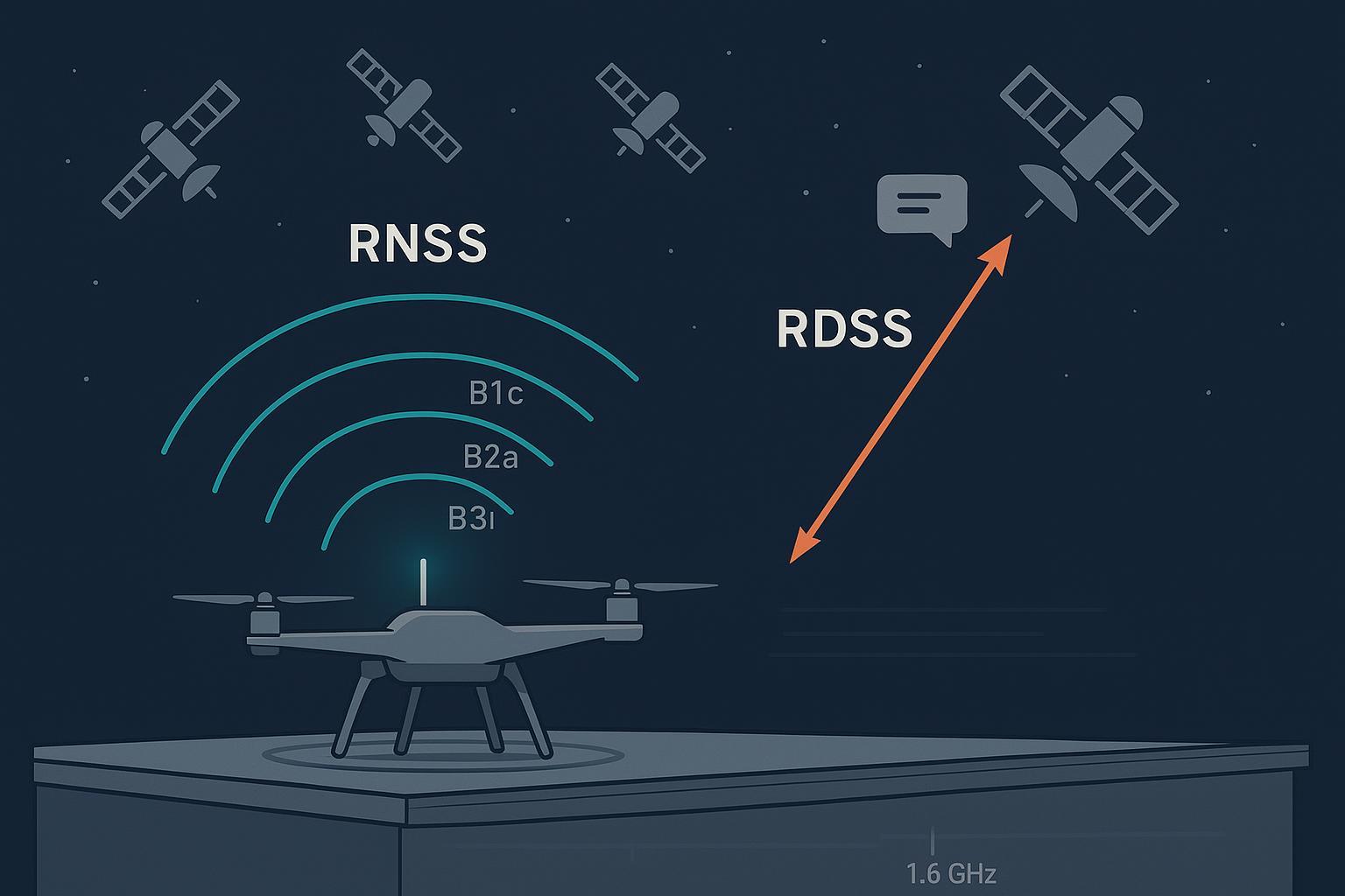
RNSS is BeiDou’s downlink navigation service used by receivers to compute PNT locally. It includes signals like B1C, B2a, B2b, and B3I. See the authoritative mapping in the ESA Navipedia BeiDou Signal Plan.
-
RDSS is a different BeiDou service family: a two‑way radiodetermination and short‑message capability historically linked to GEO satellites. It’s not the path your rover uses for carrier‑phase RTK. This distinction is documented in ESA Navipedia’s BeiDou Future and Evolutions.
Think of it this way: RNSS is the one‑way broadcast you measure precisely for RTK; RDSS is a back‑and‑forth link you might use for messaging if your requirements call for it.
BeiDou RNSS signals and frequencies
Below are common BeiDou RNSS signals and center frequencies relevant to UAV RTK. Frequency coverage depends on the receiver and antenna you select.
Signal | Center frequency (MHz) | Notes |
|---|---|---|
B1C | 1575.42 | Open‑service signal used in BDS‑3; widely supported by modern multi‑band receivers |
B2a | 1176.45 | BDS‑3 open‑service signal; valuable for multi‑frequency RTK diversity |
B2b | 1207.14 | BDS‑3 open‑service signal; support varies by receiver firmware |
B3I | 1268.52 | Broadcast across multiple orbit types; adds robustness where supported |
Sources summarized from the ESA Navipedia BeiDou Signal Plan.
What actually affects RTK on drones
Carrier‑phase RTK lives and dies on signal quality and geometric diversity. Multi‑constellation, multi‑frequency tracking (e.g., BeiDou B1C/B2a/B3I alongside GPS L1/L2 and Galileo E1/E5) accelerates ambiguity resolution and sustains a fix through brief masking or interference.
Two antenna traits consistently move the needle:
-
Phase center behavior: phase center offset (PCO) and phase center variation (PCV) stability. For high‑precision work, I aim for low PCV—single‑digit millimeters is ideal; survey‑grade designs can be tighter. Many integration manuals target PCV on the order of ≤10 mm and emphasize consistency over temperature and mounting pressure; see guidance in the u‑blox ZED‑F9P Integration Manual.
-
Axial ratio: a low axial ratio at zenith (≈ ≤2 dB is a common target in vendor guidance) improves rejection of reflected, wrong‑handed energy and helps de‑emphasize multipath in the carrier solution.
Ground plane and surroundings matter as much as the element itself. A larger, symmetric ground plane can reduce back lobes and stabilize the phase center; cramped or asymmetrical metalwork and nearby carbon fiber often inflate multipath and PCV. For a concise study of ground‑plane impact, see the peer‑reviewed analysis in ARS on added ground planes and RTK performance.
Antenna choices and mounting that move the needle
On airframes that spend time near buildings or towers, I’ve had better fix continuity with multi‑band patches that keep PCV tight across B1/B2/B3 and their GPS/Galileo counterparts. Helical antennas can shine when the sky is obstructed or you need taller, cleaner patterns above a cluttered deck, but check SWaP and mechanical resonances. If you’re operating in known interference corridors and have the budget, controlled‑reception antennas or adaptive arrays can add margin—but they’re not a free lunch and require careful integration and calibration.
Mounting specifics that consistently help:
-
Top‑center placement with an unobstructed view; keep at least one antenna diameter away from conductive structures.
-
Use an adequate ground plane under patches; avoid “tiny coaster” grounds that detune the element and boost back lobes.
-
Maintain consistent fastener torque on stacked patch assemblies so compression stays constant across the dielectric stack.
-
Weather sealing without detuning: avoid high‑dielectric covers pressed close to the radiating surface.
In one of our comparative builds, the higher‑spec antenna was a multi‑band patch from GNSource mounted on a slightly enlarged ground plane with cleaner cable routing. The goal wasn’t to advertise anything—just to keep PCV stable and axial ratio low across the bands we cared about. The change, plus integration cleanup, improved fix availability in semi‑urban flights.
If your program is weighing a step up to adaptive arrays for contested RF routes, we’ve documented when that trade actually pays off in our guide on CRPA vs single‑element antennas for UAV RTK.
Receiver and firmware settings that stabilize fixes
Receivers differ, but a few settings recur in reliable integrations:
-
Elevation mask: around 10° is a common starting point; raising it reduces low‑elevation multipath at the cost of satellites in view.
-
CN0 thresholds: track your bands’ C/N0 distributions; avoid aggressive masks that drop otherwise usable signals. Many integration guides cite ~40 dB‑Hz as a healthy mid‑elevation target, but tune to your environment.
-
Multi‑signal tracking: enable all supported BeiDou RNSS signals you can (B1C, B2a, B3I where available) alongside GPS and Galileo. The diversity helps ambiguity resolution and reduces cycle‑slip sensitivity.
-
Correction flow: keep RTCM message sets complete and correction latency/jitter low. Intermittent corrections punish fix continuity more than most people expect.
Integration hygiene: cables, phase, EMI, and filters
Cabling and layout have ended more of my test days than firmware bugs.
-
Coax choice and length: compute your insertion loss from datasheet dB/100 m at your frequency and size the cable accordingly. Very thin coax over long runs can quietly shave several dB off C/N0.
-
Phase stability: for heading‑RTK or dual‑antenna setups, phase‑match cables to within a few electrical degrees across the band and re‑verify after rework or temperature swings. For background on low‑drift dielectrics and temperature behavior, see Times Microwave’s note on phase‑stable coax design.
-
Routing and shielding: keep coax clear of high‑current ESCs, switchers, and video transmitters; add localized shielding or RF absorber near known emitters. Ferrites can help on power lines feeding noisy modules.
-
Filters: if you confirm persistent in‑band interference, consider a narrow SAW or notch filter, balancing added insertion loss against the interference reduction.
For deeper methods to quantify interference risk and jamming margin on drones, I recommend our measurement workflow in Anti‑jamming performance measurement for RTK drones.
A realistic A/B flight test: how RNSS choices paid off
We flew two otherwise identical quadrotors over three 30‑minute sorties each in a semi‑urban corridor with intermittent L‑band noise.
-
Build A used a compact dual‑band patch focused on B1C plus GPS L1 and Galileo E1, with a minimal ground plane and off‑the‑shelf coax.
-
Build B used a higher‑spec multi‑band patch covering B1C/B2a/B3I plus GPS L1/L2 and Galileo E1/E5b, on a larger, cleaner ground plane with lower‑loss coax and better routing.
Metrics we logged included time‑to‑first‑fixed, fix ratio, cycle‑slips per minute, C/N0 distributions by band, baseline residual RMS, and a simple sweep‑based jamming‑margin estimate. The tendencies were consistent with expectations:
-
Build B reached fixed sooner and stayed fixed longer, particularly near glass façades where multipath is common.
-
Cycle‑slip rates dropped on Build B thanks to multi‑frequency diversity and improved multipath rejection from the ground‑plane change.
-
C/N0 medians by band crept up a few dB, enough to keep satellites above thresholds during brief interference bursts.
-
RDSS played no role in any of these metrics because it is not part of the RTK ranging path.
If you replicate this test, keep a change log tied to KPIs. A small mechanical change—like torqueing a patch stack differently—can move PCV enough to show up in residuals.
Common mistakes I still see
-
Buying RDSS‑capable hardware expecting better RTK. RNSS drives the ranging; RDSS is for short‑message or two‑way services.
-
Under‑sized or asymmetric ground planes under patches, often right over carbon fiber, causing detuning, back lobes, and higher PCV.
-
Ignoring cable loss and phase stability; mixing lengths or dielectrics, then skipping re‑validation after rework.
-
Running coax alongside high‑current ESC leads or under video TX modules; EMI dominates your C/N0 losses.
-
Setting aggressive CN0 or elevation masks without looking at distributions; you end up dropping good signals.
-
Skipping acceptance tests; no static roof session, no baseline residual checks, no cycle‑slip audits.
Practical RTK integration checklist
-
Antenna: multi‑band RNSS coverage across BeiDou B1C/B2a/B3I plus GPS/Galileo; verify datasheet PCV and axial ratio; choose patch or helical based on sky view.
-
Ground plane and mounting: provide adequate diameter; maintain ≥1× antenna diameter clearance to conductors; apply consistent fastener torque; weather‑seal without detuning.
-
Cabling: compute insertion loss for your run; use low‑loss coax; for dual antennas, phase‑match within a few degrees; strain‑relieve connectors.
-
EMI control: route coax away from switchers, ESCs, and video TX; add shielding or absorber as needed; validate with spectrum scans where possible.
-
Firmware: set elevation mask around 10° then tune; monitor CN0 distributions; enable all supported RNSS signals; minimize correction latency/jitter.
-
Validation: perform a roof static session and three flight logs; track TTFF‑to‑fix, fix ratio, cycle‑slips/min, C/N0 by band, residual RMS; document every change.
Key takeaways
-
RDSS vs RNSS are different services; only RNSS feeds your carrier‑phase RTK.
-
Prioritize multi‑constellation, multi‑frequency RNSS coverage and a high‑quality antenna with stable PCV and low axial ratio.
-
Ground‑plane sizing and clean surroundings can matter as much as the element choice.
-
Cable loss, phase stability, and routing are silent fix‑killers; verify after every rework.
-
Tune receiver masks to your environment and keep correction latency low.
-
Consider CRPA or adaptive arrays only when interference resilience is a hard requirement and SWaP allows it.
FAQ
Q: Does RDSS help my RTK accuracy or fix stability?
A: No. RDSS is a two‑way service used for functions like short‑message communication. Carrier‑phase RTK relies on RNSS downlink signals. See the distinction in the ESA Navipedia BeiDou Future and Evolutions page.
Q: Which BeiDou signals should my antenna and receiver support for RTK?
A: At minimum, B1C alongside GPS L1 and Galileo E1. For better availability and faster fixes, add B2a and, where supported, B3I or B2b. Frequencies are summarized in the ESA Navipedia BeiDou Signal Plan.
Q: When do I need CRPA on a UAV?
A: When your route or mission profile demands resilience against jamming/spoofing beyond what a single‑element antenna and clean integration can provide. For trade‑offs and when it actually pays off, see CRPA vs single‑element antennas for UAV RTK.
Q: Any quick way to sanity‑check my cable choice?
A: Use the manufacturer’s attenuation at your RNSS frequency to compute expected dB loss for your run. If you’re phase‑sensitive (dual antennas), consider phase‑stable coax families and verify over temperature; Times Microwave’s phase‑stable coax overview is a useful primer.
Q: What acceptance tests should I run before releasing a build?
A: At least one hour of static logging and three representative flights, tracking TTFF‑to‑fix, fix ratio, cycle‑slips/min, CN0 distributions by band, and baseline residual RMS. Keep a change log tied to those KPIs.
References and further reading
-
Definitions and signal mapping are documented by ESA Navipedia: the BeiDou Signal Plan and the BeiDou Future and Evolutions pages.
-
Antenna integration targets such as axial ratio at zenith and practical receiver settings appear in vendor integration manuals like the u‑blox ZED‑F9P Integration Manual.
-
Ground‑plane effects on RTK are discussed in ARS’s study on added ground planes.
-
For cable phase stability background, see Times Microwave’s phase‑stable coax design overview.
-
For UAV‑specific interference testing methods, review our write‑up on anti‑jamming performance measurement for RTK drones.