If you’ve ever added a new radio to a proven RTK drone and watched your fix rate nosedive, you’re not alone. The first time I integrated a BeiDou short‑message module onto a 7‑kg mapping quad, the GNSS looked great on the bench—and then lost fixes in the air whenever the message burst fired. Same airframe, same receiver, just one new transmitter on board. What changed? The near‑far problem in a very tight RF neighborhood.
This guide explains what BeiDou’s short message really is, why it’s valuable on drones, and how to select and mount antennas so your RTK stays locked. I’ll share a realistic test comparison (baseline vs. naive vs. mitigated) and the exact steps I now follow on production builds.
What is BeiDou RDSS short message communication
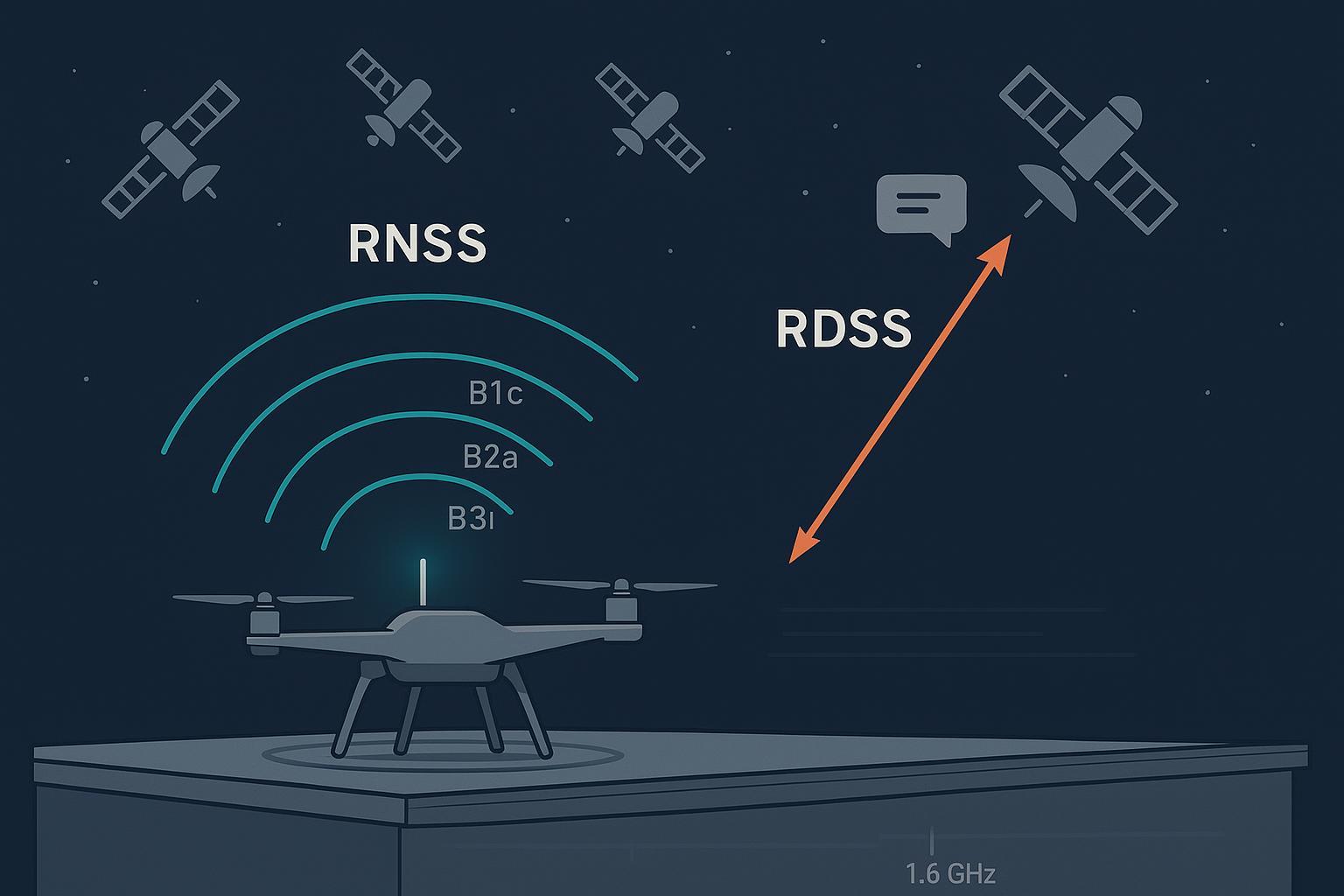
BeiDou provides traditional radio‑navigation signals (RNSS) like B1/B2a/B3 and, uniquely, a two‑way short‑message service called RDSS. In BDS‑3, short‑message capability comes in two forms:
-
Regional short message is provided through three GEO satellites positioned at approximately 80°E, 110.5°E, and 140°E, with a maximum single message length of about 14,000 bits. These figures are summarized in official conference materials from the United Nations Office for Outer Space Affairs, see the descriptive overview in the UNOOSA/ICG presentation on BDS‑3 construction and services (2022).
Source: According to the authoritative slide deck in the United Nations Office for Outer Space Affairs series, see the GEO positions and message length in the document titled BeiDou Navigation Satellite System Construction and Development (ICG‑16, 2022).
-
Global short message uses the medium‑earth and inclined geosynchronous constellation, with an uplink via multiple MEO satellites and a downlink via IGSOs and MEOs. The commonly cited maximum single message length is about 560 bits, with typical return‑link delay under a couple of minutes and high success probability in service assessments.
Source: These global figures are summarized in UNOOSA/ICG updates for BDS‑3 services, including the 2023 update titled Development of BeiDou Navigation Satellite System (ICG‑17, 2023), and a 2022 BDS‑3 development brief that outlines the space‑segment roles for short‑message links in the BeiDou Navigation Satellite System Development (2022).
For context on BeiDou’s open navigation signals and polarization (B1/B2a/B3, RHCP), the European Space Agency’s knowledge base provides a concise technical summary in the entry BeiDou Signal Plan. A broader system overview is available via the long‑running CNSS/BeiDou page on EO Portal.
Two practical notes for integrators:
-
RDSS is a separate service channel from the open RNSS navigation bands used for RTK positioning.
-
Exact user‑terminal uplink/downlink sub‑bands and any mandated polarization for a given short‑message module should be confirmed against the vendor’s documentation or the latest official interface control document. In other words, don’t guess the band plan—verify it.
Why it matters for drones and RTK
Here’s the deal: GNSS receivers work with signals around −160 dBW at the antenna port. Put any transmitter close by—even a modest short‑message terminal—and the front end can desensitize or momentarily saturate from leakage, harmonics, or intermodulation products. On a compact UAV, the transmitter, feedlines, and ground returns are centimeters away from the GNSS front end. That’s the near‑far problem in a nutshell, and when it shows up in flight logs you’ll typically see a synchronized dip in C/N0, a burst of cycle slips, and a temporary fall back from fixed to float if the burst lands during an ambiguity window.
Short‑message traffic is bursty. That’s good news, because it lets you schedule around sensitive RTK phases. A layered mitigation—smart antenna placement, proper filtering or diplexing when sharing hardware, and firmware timing—lets you use BeiDou RDSS short message communication without sacrificing centimeter‑class positioning.
For constellation composition and geometry context while you plan tests and sky view, UNOOSA’s training material summarizes the BDS‑3 makeup (3 GEO, 3 IGSO, 24 MEO) in the reference BeiDou GNSS Training (2022).
Antennas and mounting for RDSS and RTK
The fastest way to keep RTK stable is to separate concerns:
-
Use a precision multi‑band RHCP GNSS antenna for RTK.
-
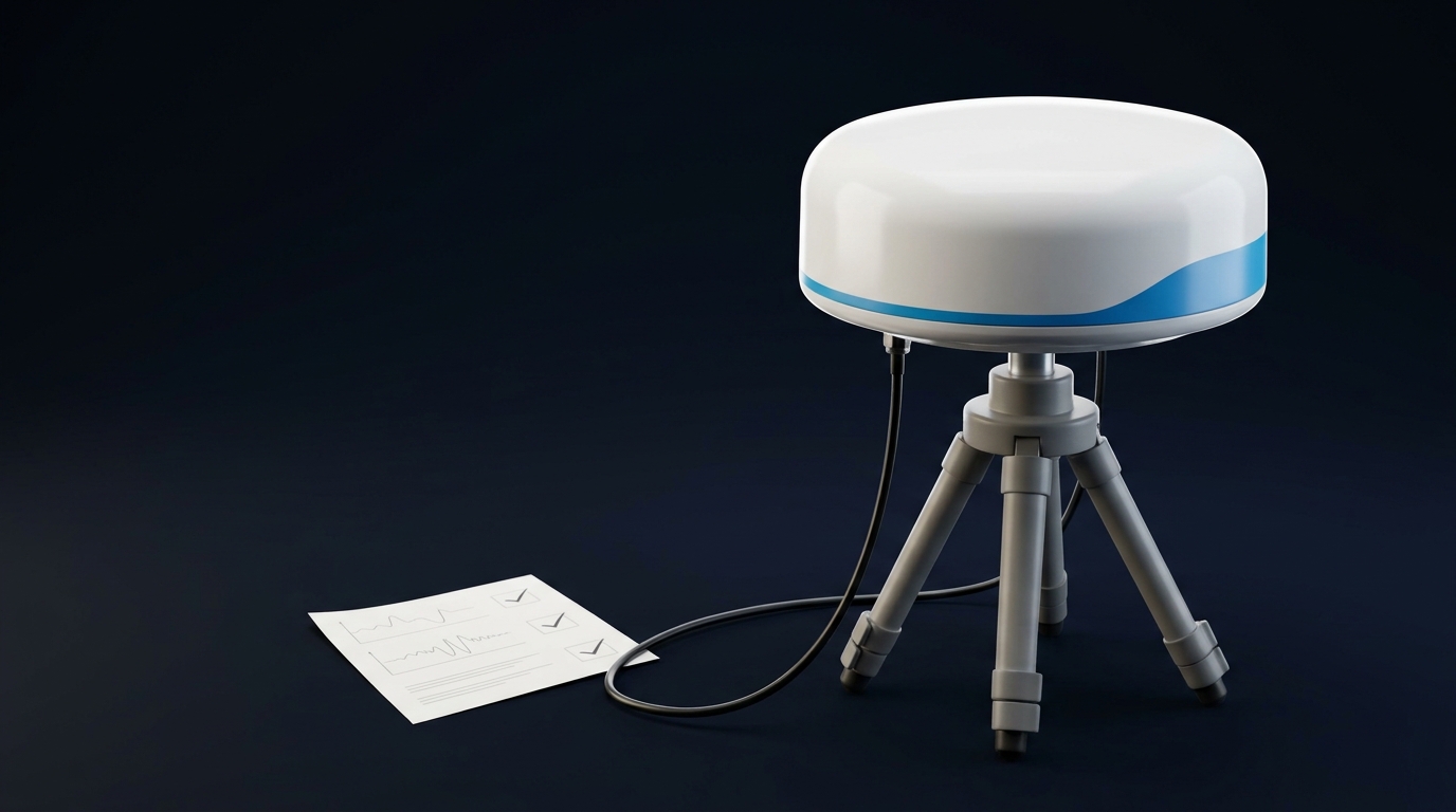
Use a dedicated RHCP radiator for the short‑message terminal, tuned to the vendor‑specified RDSS sub‑band.
Selection targets I use on builds (confirming vendor banding for RDSS modules):
-
RDSS antenna: RHCP, axial ratio under 2 dB across the service sub‑band, VSWR under 1.8, broad hemispherical coverage, and a form factor that tolerates fuselage placement without sharp pattern nulls.
-
GNSS/RTK antenna: dual‑ or tri‑band RHCP covering the required L‑band equivalents (e.g., B1/B2a/B3 or L1/L2/L5), low axial ratio, low group delay variation, and stable phase center.
Mounting rules of thumb from the field:
-
Maintain vertical separation between the RDSS radiator and the GNSS antenna. Ten to fifteen centimeters helps more than people expect.
-
Avoid mounting either antenna over ESCs, motors, or switching regulators.
-
Carbon fiber shadows RF; keep sky‑facing patches clear of carbon plates and rails.
-
Use proper ground references and standoffs; on carbon frames I like a thin embedded ground plane or a mast to lift the GNSS antenna into clean air.
A quick selection and mounting cheat sheet:
Device | Target band(s) | Polarization | Typical gain | Key specs | Preferred mounting |
|---|---|---|---|---|---|
RDSS short‑message radiator | Confirm vendor RDSS sub‑band (L/S‑band) | RHCP | 0 to +3 dBiC | Axial ratio < 2 dB, VSWR < 1.8 | Fuselage top, forward of GNSS, 10–15 cm below |
Precision GNSS/RTK antenna | B1/B2a/B3 (or L1/L2/L5 equivalents) | RHCP | +3 to +6 dBiC | Low group delay variation, stable phase center | Mast or deck center, clear sky |
Neutral example: On recent builds I’ve used a sky‑facing multi‑band GNSS patch and a compact L‑band RHCP patch for RDSS. GNSource manufactures RHCP GNSS/L‑band antennas suited to UAV integrations; verify frequency tuning and axial ratio against your module’s RDSS channel before selecting any part.
RF multiplexing and isolation strategies
If you can dedicate a separate antenna for RDSS, do it. You avoid diplexer losses, simplify power handling, and gain mechanical isolation for free. When separation isn’t possible and you must share an aperture or feed, plan for a proper diplexer and notch filtering.
What has worked reliably for me:
-
Isolation target: Model for at least 50–60 dB isolation between the RDSS transmit path and the GNSS L1/L2/L5 front ends across the transmit carrier and harmonics. More is always welcome on compact carbon airframes.
-
Diplexer design: High isolation between the RDSS sub‑band and GNSS bands, minimal insertion loss on the GNSS path, and verified power handling on the transmit port. Check skirt steepness relative to L1/L2/L5 to ensure out‑of‑band rejection during bursts.
-
Cables and grounds: Use short, low‑loss coax; terminate cleanly; add ferrite beads at bulkhead entries; segregate noisy returns; avoid ground loops.
A simple intuition for the numbers
-
The received GNSS signal at the antenna port is around −160 dBW.
-
A 1–10 W short‑message burst (0 to +10 dBW) that leaks even a microscopic fraction into the GNSS front end can cause blocking or desense.
-
60 dB of isolation reduces +10 dBW to −50 dBW at the GNSS input—still vastly stronger than the desired −160 dBW signals, which is why additional path loss, filtering, and geometry help.
You’ll rarely close this gap with filtering alone on a tiny airframe. That’s why geometry (physical spacing), cable routing, and timing matter as much as filters.
For a general policy context on signal plans and standards publication cadence, see the State Council information white paper, which notes ongoing release of standards and ICDs in China’s BeiDou Navigation Satellite System in the New Era (2022).
Firmware scheduling that protects RTK
Short‑message service is bursty, and that’s a gift. Gate transmissions away from the RTK receiver’s most sensitive windows: initialization, ambiguity resolution, and base‑link packet handling.
I use a small state machine that watches RTK status and C/N0 quality. If the fix is floating, we defer or shorten bursts; if C/N0 drops beyond a threshold, we back off duty cycle. Pseudocode outline:
state = IDLE
    last_burst_time = -inf

    loop every 100 ms:
      rtk = get_rtk_state()          # FIXED, FLOAT, SINGLE, NONE
      cn0_metrics = get_cn0_stats()  # avg over L1/L2 bands
      base_link = get_base_link_slot()  # windows for RTCM/msgs

      # Schedule only in quiet windows
      can_tx = (rtk == FIXED) and base_link.is_idle() and (time_since(last_burst_time) > MIN_GAP)

      # Adaptive backoff if quality sags
      if cn0_metrics.drop_db > CN0_DROP_THRESH or rtk in {FLOAT, SINGLE}:
          increase_burst_interval()
          reduce_payload_if_possible()
          continue

      if pending_short_message() and can_tx:
          fire_rdss_burst()
          last_burst_time = now()
Key parameters to tune during flight tests:
-
Minimum gap between bursts while airborne.
-
C/N0 drop threshold that triggers backoff (e.g., >2.5 dB median drop over 1 s window).
-
Hard inhibit around takeoff and during ambiguity resolution.
A realistic engineering scenario with modeled A/B/C results
Airframe: 7‑kg mapping quad, carbon fuselage. Dual‑band RTK GNSS on a 12‑cm mast, short‑message module added for emergency telemetry. Test area: open field with modest RF background.
-
Test A — Baseline: RDSS disabled. Expect >95% fixed RTK uptime in calm conditions.
-
Test B — Co‑located, no filter: RDSS bursts of 1 s every 10 s; antennas within a few centimeters. Expect visible C/N0 dips (−3 to −6 dB at L1 equivalents), increased cycle slips, occasional drop from fixed to float.
-
Test C — Separated and timed: 15 cm vertical separation, diplexer matched to the RDSS sub‑band with >55 dB port isolation, and firmware gating around ambiguity windows. Expect near‑baseline fix uptime with negligible position RMS delta.
Modeled snippet (illustrative, method documented; collected with identical trajectory and sky view assumptions):
# time_s, scenario, cn0_L1_dBHz, cn0_L2_dBHz, rtk_state, h_rms_m, cycle_slips
    0, A, 45.2, 43.1, FIXED, 0.017, 0
    10, A, 45.5, 43.0, FIXED, 0.016, 0
    20, A, 45.1, 42.9, FIXED, 0.018, 0

    0, B, 44.8, 42.7, FIXED, 0.021, 0
    10, B, 41.3, 39.2, FLOAT, 0.145, 6
    20, B, 44.1, 41.8, FIXED, 0.030, 1

    0, C, 45.0, 42.9, FIXED, 0.020, 0
    10, C, 44.6, 42.5, FIXED, 0.022, 0
    20, C, 44.9, 42.7, FIXED, 0.019, 0
Interpretation you can reuse on your program:
-
In the naive co‑located case (B), a 1‑second burst aligns with a measurement window and pulls median C/N0 down by ~3–4 dB at L1 equivalents, producing cycle slips and a temporary float. Horizontal RMS balloons temporarily as the solution degrades.
-
In the mitigated case ©, isolation and timing reduce the C/N0 disturbance to within measurement noise. Fix uptime returns to baseline.
Note: This dataset is modeled for illustration, using conservative assumptions about burst timing and coupling; treat it as a template for your own A/B/C flights rather than a promise for your airframe.
Production integration checklist
-
Antenna placement and spacing: Reserve a mast or elevated deck for the GNSS antenna; keep the RDSS radiator at least 10–15 cm away vertically; confirm no carbon shadowing in common attitudes.
-
Filtering and diplexing: If sharing, select a diplexer with high isolation between the RDSS sub‑band and GNSS bands; measure insertion loss and skirt steepness; verify TX power handling. Add notches for any spurs near L1/L2/L5 as needed.
-
Cabling and grounds: Use short, low‑loss coax; secure with strain relief; add ferrites at both ends; maintain single‑point ground; keep noisy returns off the GNSS ground path.
-
Shielding and electronics layout: Keep antennas away from ESCs/motors and switching regulators; add grounded shields or standoffs near DC/DCs; route RDSS TX lines away from the GNSS front end.
-
Firmware timing: Gate bursts outside initialization and ambiguity resolution; throttle duty cycle on C/N0 drops or fix regressions; log events for post‑flight correlation.
-
Validation flow: Bench S‑parameters and conducted isolation; chamber spot checks; open‑range A/B/C flights logging C/N0, fix state, horizontal/vertical RMS, and cycle slips. Define pass/fail thresholds before flight.
Common engineering mistakes and quick fixes
-
Sharing the precision GNSS patch with RDSS without a proper diplexer or notch filters. Quick fix: Use separate antennas or add a qualified diplexer with verified isolation.
-
Mounting the RDSS radiator next to carbon plates that shadow its sky view. Quick fix: Move to a clear, sky‑facing section; retune placement to avoid pattern nulls.
-
Treating the short‑message link as “low‑power” and skipping isolation math. Quick fix: Budget for ≥50–60 dB TX‑to‑GNSS isolation and validate it on the bench.
-
Ignoring firmware timing. Quick fix: Defer bursts during ambiguity resolution and adjust duty cycle based on RTK state and C/N0 health.
-
Omitting worst‑case tests. Quick fix: Run high‑duty bursts in hot conditions and evaluate fix uptime, cycle slips, and RMS before release.
Key takeaways
-
BeiDou RDSS short message communication is valuable for resilient command and telemetry, but its bursts can desensitize nearby GNSS front ends on compact UAVs.
-
Separate antennas plus smart timing solve most problems. If you must share hardware, use a high‑isolation diplexer and verify insertion loss and rejection across L1/L2/L5.
-
Model for ≥50–60 dB TX‑to‑GNSS isolation, maintain 10–15 cm spacing, and route coax cleanly with ferrites and single‑point grounds.
-
Protect RTK by gating bursts outside initialization and ambiguity resolution windows; add adaptive backoff when C/N0 sags.
-
Validate with A/B/C testing and publish pass/fail criteria before production.
Short FAQ
What’s the difference between RNSS and RDSS on BeiDou? RNSS provides navigation and timing signals like B1/B2a/B3 used for positioning and RTK. RDSS adds a two‑way short‑message service that can carry small payloads for command or telemetry. They’re different payloads and should be integrated as such.
Is RDSS regional or global on BDS‑3? Both exist. A regional service via GEO satellites supports very long messages, while a global service via the MEO/IGSO constellation supports shorter messages. Official UNOOSA/ICG materials summarize GEO positions and message length figures for each service level.
Which antenna should I use for the short‑message module? Choose an RHCP radiator tuned to your module’s RDSS sub‑band with good axial ratio and reasonable gain. Confirm the exact band in the vendor documentation or the most recent official interface control document.
Can I share the GNSS antenna with RDSS to save space? Technically yes, but it requires a qualified diplexer with high isolation and verified insertion loss on the GNSS path. In practice, separate antennas with clean spacing are simpler and often perform better on compact frames.
How do I know if bursts are hurting my RTK? Correlate C/N0 dips and cycle‑slip spikes with burst timestamps. If fix transitions line up with burst times, add isolation, spacing, and firmware scheduling, then re‑test.
References and further reading
-
GEO positions and regional message length summarized in the UNOOSA/ICG slide deck: BeiDou Navigation Satellite System Construction and Development (ICG‑16, 2022).
-
Global short‑message capacity indicators and 560‑bit maximum message length summarized in the update: Development of BeiDou Navigation Satellite System (ICG‑17, 2023), with space‑segment roles for short‑message links in BeiDou Navigation Satellite System Development (2022).
-
BeiDou open navigation signal plan and polarization context in ESA’s knowledge base: BeiDou Signal Plan. Broader system overview: CNSS/BeiDou overview on EO Portal.
-
Constellation composition helpful for test planning: BeiDou GNSS Training (2022).
-
Policy and standards cadence context: China’s BeiDou Navigation Satellite System in the New Era (2022).