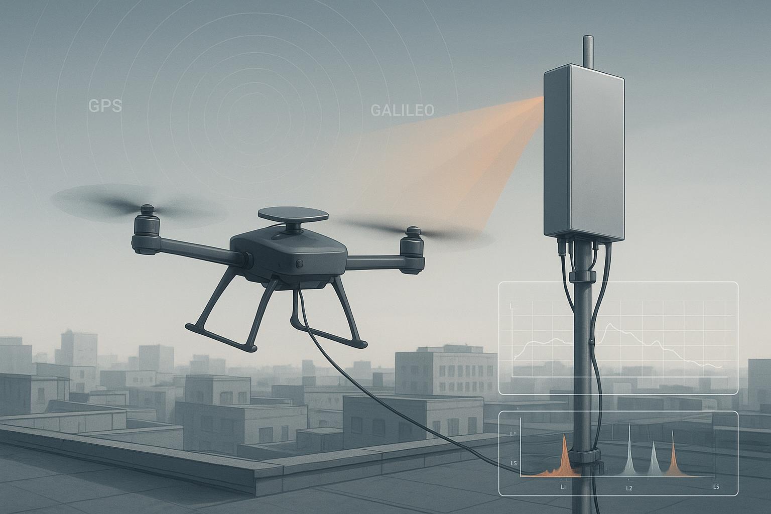
I still remember the first time an inspection drone slipped from fixed RTK to float while we hovered over a telecom yard. C/N0 fell across L1, the AGC yanked the front‑end gain, and our horizontal RMS drifted into decimeter territory. The logs told a simple story: a narrowband uplink spur near L1 spiked the noise floor. The lesson was clearer—resilience isn’t a checkbox; it’s something you measure, tune, and re‑measure.
This article details how I measure anti‑jamming performance for RTK‑capable UAVs — the testing counterpart to our ultimate guide to anti-jamming GNSS antennas — with procedures you can replicate. We’ll define the KPIs that matter, outline lab/chamber and field setups, and share working thresholds that tie directly to RTK behavior.
The concepts that matter for anti-jamming performance measurement
Let’s align on terms we’ll actually use on the bench.
-
J/S (jammer‑to‑signal ratio): J/S (dB) = J(dBm) − S(dBm). It’s the jammer power relative to the desired GNSS signal at the receiver input. System “capability” is the combination of antenna rejection (e.g., CRPA nulling) and receiver processing. For foundational context, see the Rohde & Schwarz testing overview in GPS World’s piece on testing GNSS receivers against jamming and spoofing: Testing GNSS receivers against jamming and spoofing (GPS World, R&S).
-
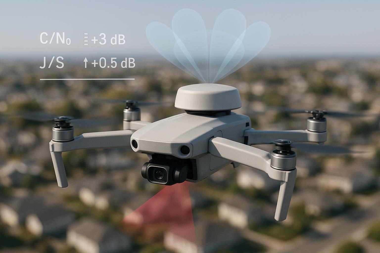
Null depth (CRPA): The attenuation (in dB) achieved in the jammer’s direction when the array steers an adaptive null. Commercial 4‑element systems often show ~20–40 dB in literature and datasheets, while higher‑end 7+ element arrays can exceed that, though specs vary by product and setup. For accurate null measurement, anechoic chamber reflectivity should be low (≈ −30 dB or better) to avoid masking the null; see the NSI‑MI chamber design note: Basic rules for indoor anechoic chamber design (NSI‑MI).
-
C/N0 and AGC behavior: As total input power rises (noise + interference), the receiver’s AGC reduces gain to protect the ADC, which “desenses” satellite channels and depresses estimated C/N0. A sustained C/N0 below the high‑30s dB‑Hz is commonly associated with tracking risk; robust fixed RTK typically benefits from at least one band maintaining ≳40 dB‑Hz, though exact thresholds are receiver‑specific. For a practical overview of RFI impacts on C/N0, see GPS World’s expert advice: The impact of RFI on GNSS receivers (GPS World).
-
Ambiguity resolution and fix state: For RTK, the KPIs that truly matter are fix rate (% of epochs in fixed), time‑to‑fix/re‑fix, and position RMS. Everything else—J/S, C/N0, null depth—explains “why” those RTK KPIs change.
Why these KPIs matter for RTK on UAV platforms
-
Fixed→Float transitions: As J/S climbs, you’ll usually see C/N0 fall and cycle‑slip bursts rise. The receiver often downgrades to float before complete loss‑of‑lock. That transition is the money point: it’s where centimeter‑level positioning gives way to decimeter‑plus drift.
-
Long re‑fix times: After interference subsides or the UAV maneuvers out of the lobe, time‑to‑re‑fix governs operational downtime. If you’re flying automated corridors or hovering near critical assets, 60+ seconds to re‑fix is painful.
-
Navigation jumps and integrity: Even if lock persists, phase tracking stress can create jumps and higher RMS—especially vertically. Mapping KPIs to these effects helps you know whether the antenna/receiver stack is good enough for the mission.
Working KPIs and pragmatic thresholds to log
Treat these as working targets to validate on your own platform; receivers and arrays differ.
-
J/S breakpoints: Identify the J/S at which (1) first float occurs, (2) first loss‑of‑lock occurs, and (3) recovery point after interference. Log them per band. Literature discusses detection in the ~20–30 dB range for certain methods, but platform‑specific loss‑of‑lock points vary considerably.
-
Null depth: For small UAV CRPAs, a baseline acceptance is ≥20–30 dB. Harsher environments benefit from ≥30–40 dB where array geometry/SWaP allows. Measure median and max null depth and note adaptation time.
-
C/N0 guidance: As a pragmatic range, aim to maintain ≥40 dB‑Hz on at least one band for robust fixed RTK, and beware sustained periods in the mid‑30s dB‑Hz where tracking risk rises. Treat this as guidance, not a universal threshold.
-
RTK fix rate and convergence: In mild interference, target >90–95% fixed rate and <30 s re‑fix. Log fix rate versus J/S and time‑to‑re‑fix after disturbances.
-
Positional RMS: Track horizontal and vertical RMS while ramping interference. Annotate when RMS exceeds mission tolerances.
Citations and scaffolding: GPS World testing overview (R&S) and RFI impact explainer (GPS World).
Lab recipe: from clean baseline to controlled interference ramps
Equipment (minimum practical set):
-
Multi‑band GNSS simulator or sky‑sim feed with RTCM corrections for RTK
-
Vector signal generator(s) for interferers (CW, AWGN, chirp)
-
Calibrated RF combiners/couplers, power meters, and attenuators
-
Spectrum analyzer (or receiver IF tap + analysis) to verify injected spectra
-
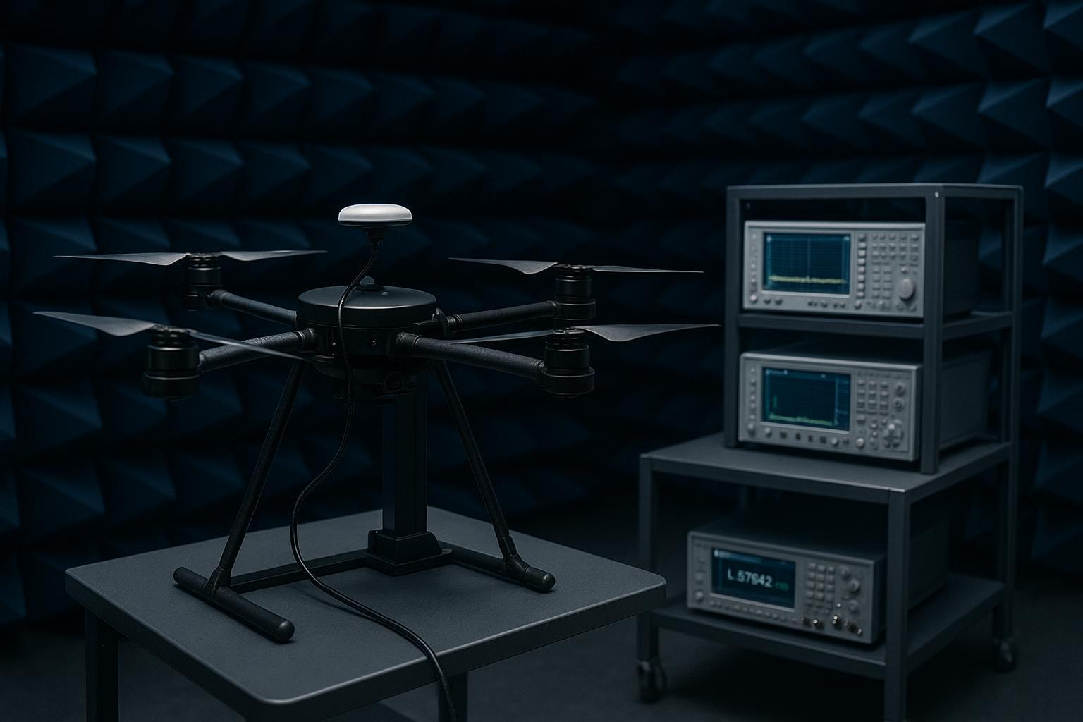
For CRPA/OTA: Anechoic chamber or shielded box with positioner/rotator
-
Data logger to capture per‑epoch: PRN, band, C/N0, AGC, satellites tracked, RTK status, H/V RMS, cycle‑slips; optional IF snapshots
Conducted interference ramp (repeat per band and interferer type):
-
Baseline: Run 10–15 minutes of clean simulation across L1/L2/L5. Achieve fixed RTK with stable C/N0 and low RMS. Record mean/σ for all KPIs.
-
Inject CW near the band center via calibrated combiner. Start low (e.g., −120 dBm at DUT reference plane). Increase in 2 dB steps every 60–120 s. At each step, log: per‑satellite C/N0, AGC, satellites tracked, RTK status, H/V RMS, and cycle‑slips. Mark first float, first significant cycle‑slip burst, and first loss‑of‑lock.
-
Repeat with broadband AWGN and with a swept narrowband interferer to emulate LTE‑like leakage. Document J/S precisely: measure jammer power and desired signal power at the same reference plane.
-
Plot: RTK fixed‑rate vs J/S; C/N0 vs jammer power; AGC vs time; annotate breakpoints. Save raw CSVs.
OTA/chamber null‑depth mapping for CRPA:
-
Mount the array on a low‑reflection fixture at the chamber sweet spot; verify chamber reflectivity (≈ −30 dB or better) per NSI‑MI guidance.
-
Use a standard‑gain or horn antenna driven by the vector signal generator as the “jammer.” Fix EIRP and geometry.
-
With null‑steering active, sweep azimuth 0–360° in 5° steps at one or more elevations (e.g., 15°, 30°, 45°). At each angle, measure received power at the beamformer output or equivalent metric; compute attenuation relative to nominal.
-
Repeat for different interferer types (CW vs swept) and log convergence time for adaptive nulling.
Vendor references for methodology and tooling: Spirent whitepaper on characterizing CRPAs and R&S SMW200A GNSS simulation video.
Data structures to capture (CSV fields): timestamp, PRN, band, C/N0 (dB‑Hz), AGC (dB), satellites tracked, RTK status (fixed/float), H_RMS (m), V_RMS (m), interferer_type, interferer_power_dBm, measured_J_dBm, measured_S_dBm, computed_J_S_dB, note_flags.
Field validation and regulatory safety
Active jamming in the field without authorization is illegal in many jurisdictions and dangerous in all of them. Use shielded boxes or anechoic chambers for most tests. If you must validate outdoors, do it at a licensed, controlled range with RF monitoring and NOTAMs/coordination as appropriate. The aviation community provides clear guidance—see the 2026 FAA resource guide and EUROCONTROL’s testing guide for process, licensing, and containment expectations: FAA GNSS Interference Resource Guide (2026), EUROCONTROL GNSS interference testing guide (2023).
Field checklist (sanitized for legality and safety):
-
Use the minimum effective jammer power; prefer low‑power conducted injection or shielded OTA whenever possible.
-
Coordinate permits, NOTAMs (if applicable), and RF monitoring with spectrum control authorities.
-
Establish ground truth via RTK base/CORS; log rover and base data for post‑processing.
-
Pre‑flight EMI sweep of the test area; ensure no unintended victims in adjacent bands.
-
Scripted flight profiles (hover, orbits, corridors) with repeatable headings relative to the interferer.
-
Real‑time telemetry of KPIs (C/N0, AGC, RTK state) and independent spectrum logging if feasible.
Integration checklist: antenna, mounting, cabling, shielding, firmware
Mounting and geometry
-
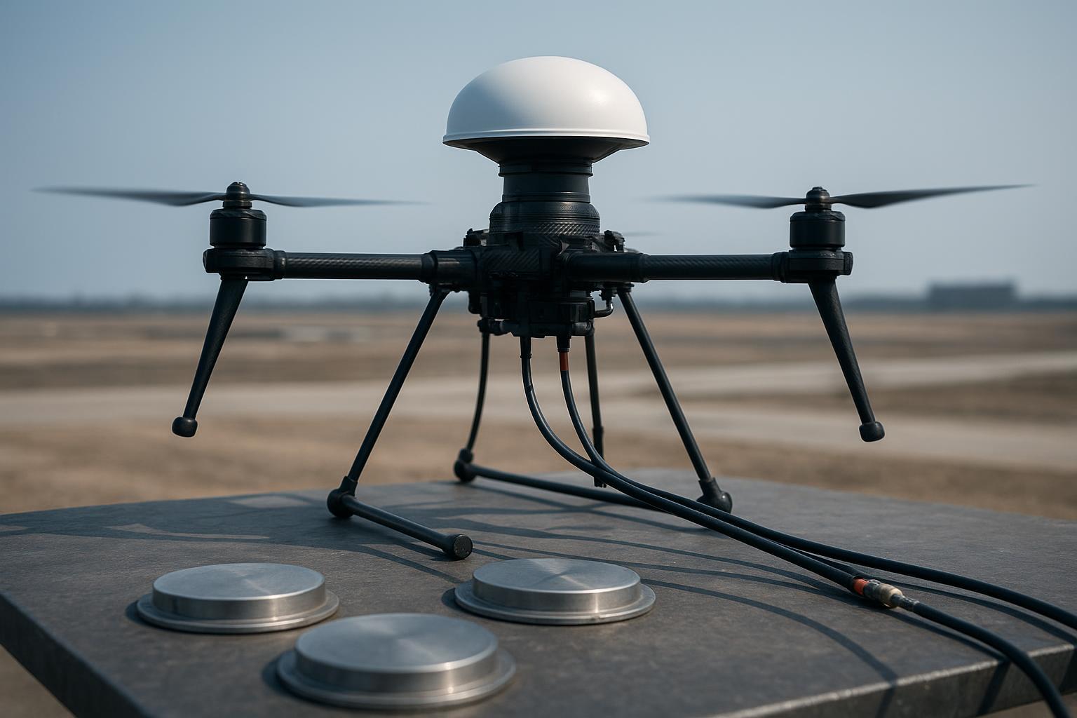
Top‑center mounting with a clear sky view; avoid booms and carbon fiber edges near the antenna or array.
-
For CRPAs, preserve element geometry and spacing; ensure a rigid mount and minimize nearby conductive structures that distort patterns.
-
Ground plane: Add or extend a conductive backplane; treat it as part of the antenna system. Validate its effect in chamber or on a low‑RCS rig.
Cabling and phase consistency
-
Use low‑loss coax with phase stability across temperature and vibration.
-
For multi‑element arrays, length‑match and phase‑match; as a working target, keep phase mismatch ≲1° at L1. Verify with VNA or TDR and document results.
-
Use ferrite chokes and shielding at cable penetrations; seal connectors and strain‑relieve.
Shielding and onboard EMI
-
Gasket enclosure seams; isolate high‑speed digital lines; route switching supplies away from L‑band harnesses.
-
Consider conductive coatings and absorbers inside the fuselage to reduce internal reflections.
Firmware and receiver configuration
-
Log AGC, filter/notch states, and constellation/band weighting; store the exact configuration with each data run.
-
Use notch filters cautiously—overly tight notches can destabilize tracking. Validate any DSP countermeasures against your interference scripts.
Validation and reporting
-
Maintain a clean baseline set, then overlay interference runs for apples‑to‑apples plots.
-
Summarize with graphs: fixed‑rate vs J/S, C/N0 vs jammer power, null‑depth polar plots, and time‑to‑re‑fix distributions.
A realistic scenario you can replicate
We reproduced the telecom‑yard issue by injecting a swept narrowband interferer around L1 while flying a scripted hover/orbit profile in a licensed range and by mirroring it in a chamber. We compared three antennas on the same rover/airframe: a passive reference puck, a compact 4‑element CRPA, and a 7‑element CRPA.
Representative results (your numbers will vary):
-
Passive reference: Fixed→float occurred near J/S ≈ −2 to +2 dB depending on geometry; time‑to‑re‑fix after spur reduction ranged 20–45 s. Vertical RMS expanded to >0.3 m during float.
-
4‑element CRPA: Achieved null depths ~25–32 dB at favorable angles; maintained fixed RTK up to ≈ +12 to +18 dB J/S in those sectors; re‑fix <20 s after spur reduction.
-
7‑element CRPA: Deeper nulls in the test set (~30–38 dB) and broader angular coverage; maintained fixed up to ≈ +22 to +28 dB J/S when the jammer direction aligned for a strong null; re‑fix commonly <10–15 s.
The polar diagram below illustrates how null depth appears in practice and why mounting/geometry matter.
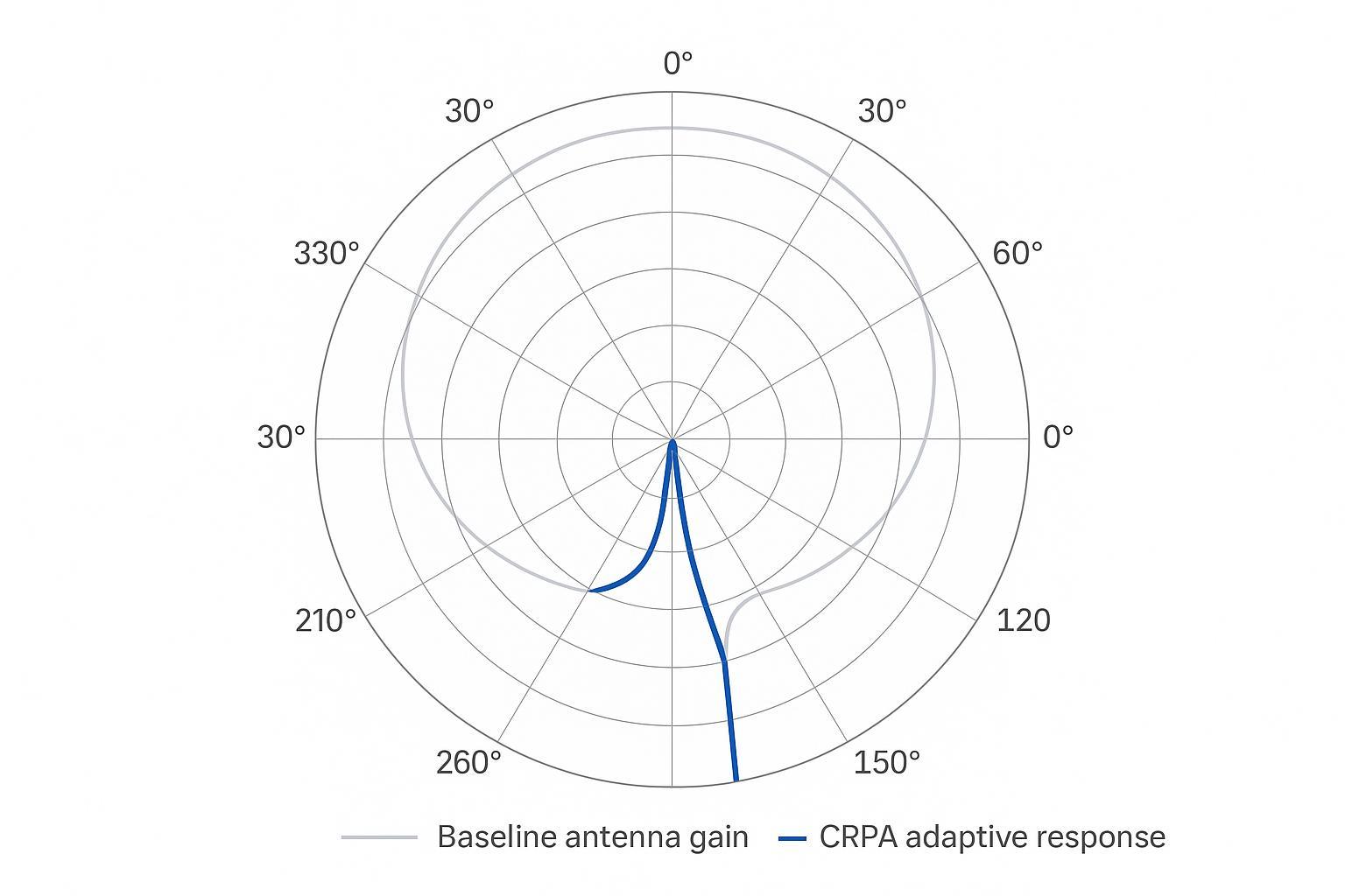
What should you take from this? Not that any one array “wins” universally, but that array geometry, calibration, and mounting can buy you 15–25 dB of additional J/S margin in sectors where the null lands—and that’s often the difference between staying fixed and going float.
Practical improvement checklist
-
Establish a clean baseline (no interference) and lock in fixed RTK before any ramps.
-
Use small, consistent jammer steps (e.g., 2 dB/60–120 s) and repeat each script twice for confidence.
-
Map null depth with 5° azimuth steps at multiple elevations; verify chamber reflectivity.
-
Length‑match and phase‑match multi‑element cables; document VNA results.
-
Add/verify a ground plane and check that mounting doesn’t shadow the sky view.
-
Log AGC, C/N0, filter states, and RTK status per epoch; export IF snapshots around breakpoints.
-
Validate DSP countermeasures (notch, weighting) against both CW and swept narrowband cases.
-
Plan a licensed outdoor sanity check that mirrors the chamber scripts; monitor the spectrum independently.
-
Define pass/fail based on RTK fix‑rate, time‑to‑re‑fix, and RMS, not only C/N0.
-
Archive raw CSVs, plots, and configuration files for reproducibility.
FAQ: short answers to common questions
Q: How many times should the target keyword “anti-jamming performance measurement” appear? A: Use it naturally—title, one H2, and a few body mentions are enough. Avoid stuffing.
Q: Is conducted testing enough, or do I need a chamber? A: Conducted ramps are ideal for precise J/S breakpoints. You need OTA/chamber work to measure null depth and array behavior across angle.
Q: What J/S margin should I expect from a CRPA? A: It depends on element count, calibration, and geometry. Seeing 15–25 dB of additional margin in favorable sectors is realistic in many small‑array setups.
Q: What C/N0 is “good enough” for fixed RTK? A: Treat ≥40 dB‑Hz on at least one band as a working target. Validate on your receiver; some maintain fixed below that with multi‑band diversity.
Q: Are tight notch filters a silver bullet? A: No. They can help for narrowband interferers but may degrade code/carrier tracking if over‑tight. Test them across your interferer set.
Q: Can I do outdoor jamming tests without permits? A: Don’t. Use licensed ranges or shielded environments and follow aviation/spectrum guidance from authorities like the FAA and EUROCONTROL.
Measuring anti‑jamming performance is ultimately about tying lab‑grade RF control to mission‑grade RTK observables. Define your KPIs, script your tests, and let the data guide antenna selection, mounting, and firmware choices. Then re‑test after every integration change—because resilience is engineered, not assumed.