TL;DR (2026): If your fleet routinely flies in high‑threat or dense urban RF where jammers and spoofers show up, a 4–7 element CRPA can preserve RTK availability by spatially nulling interferers—expect indicative 20–40 dB J/S margin gains with well‑calibrated arrays and ~30–50 dB null depths. If you fly mainly rural mapping with tight SWaP and budgets, a well‑mounted single‑element antenna remains the simpler, lighter, cheaper choice. Most teams should at least make their airframes CRPA‑ready (mounting diameter and power) even if they start with a single element.
A field engineer’s setup: urban canyon vs rooftop range
Last fall we ran two back‑to‑back RTK missions to debug intermittent drops in a utility inspection corridor:
-
Airframe A: dual‑band single‑element patch on a 100 mm ground plane, 38 g, coax loss <1.5 dB.
-
Airframe B: 6‑element CRPA (∼220 mm dia, λ/2 spacing at L1), external processor, 9 W typical.
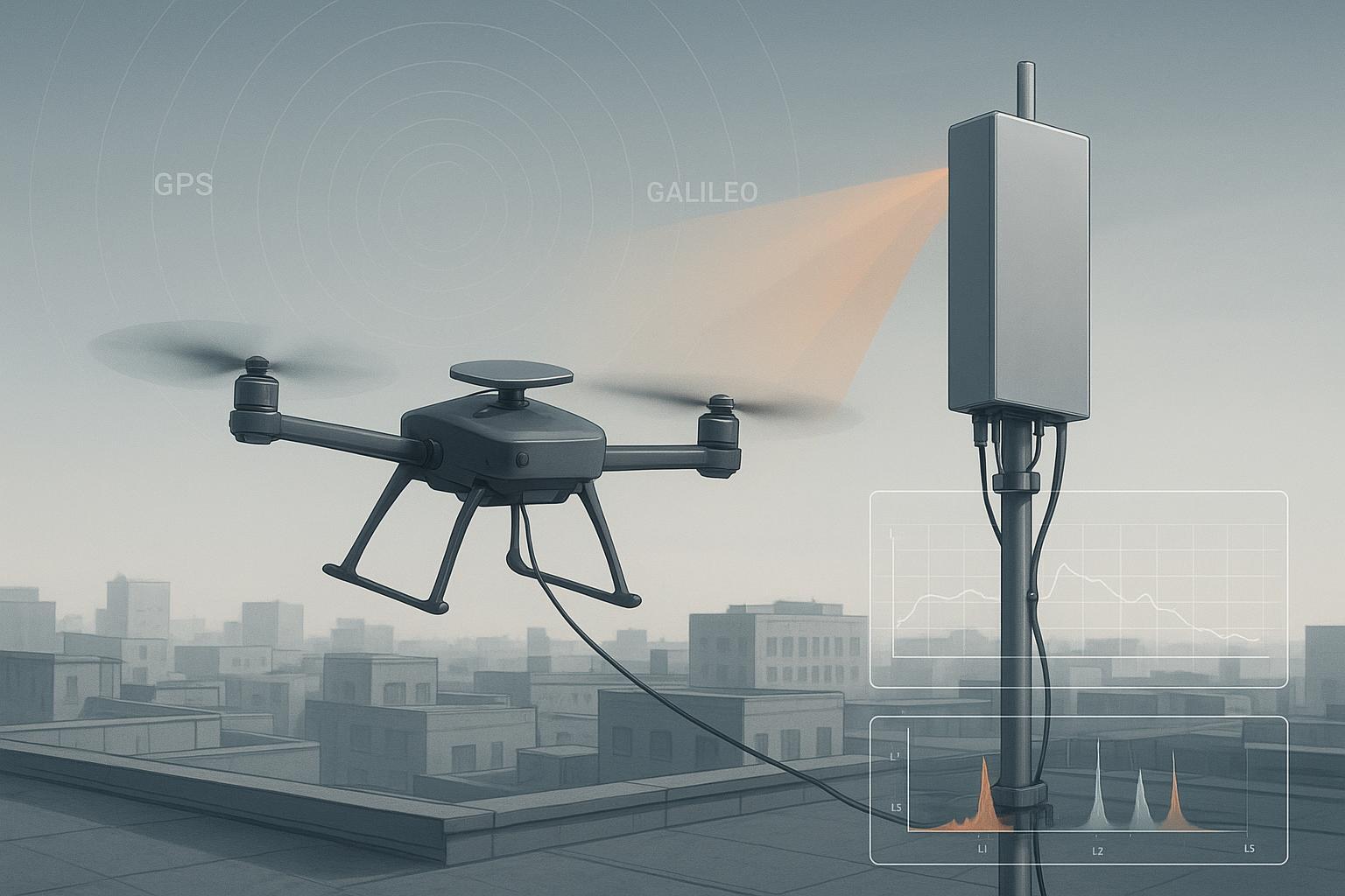
In the urban canyon segment, Airframe A fell from fixed RTK to float three times (C/N0 dips, cycle‑slip bursts) and once lost lock when a narrowband interferer spiked near L1. On the rooftop range with a controlled continuous‑wave source 25–30 dB above thermal, Airframe B held fix while steering a null at the interferer’s angle; integer ambiguities reconverged within ~15–25 s after each scripted maneuver. Same receiver family, same base corrections, different spatial filtering. That contrast is the heart of CRPA vs single‑element antenna trade‑offs for UAV RTK. For the full anti-jam picture behind the array side, see our ultimate guide to anti-jamming GNSS antennas.
Key concepts, fast
-
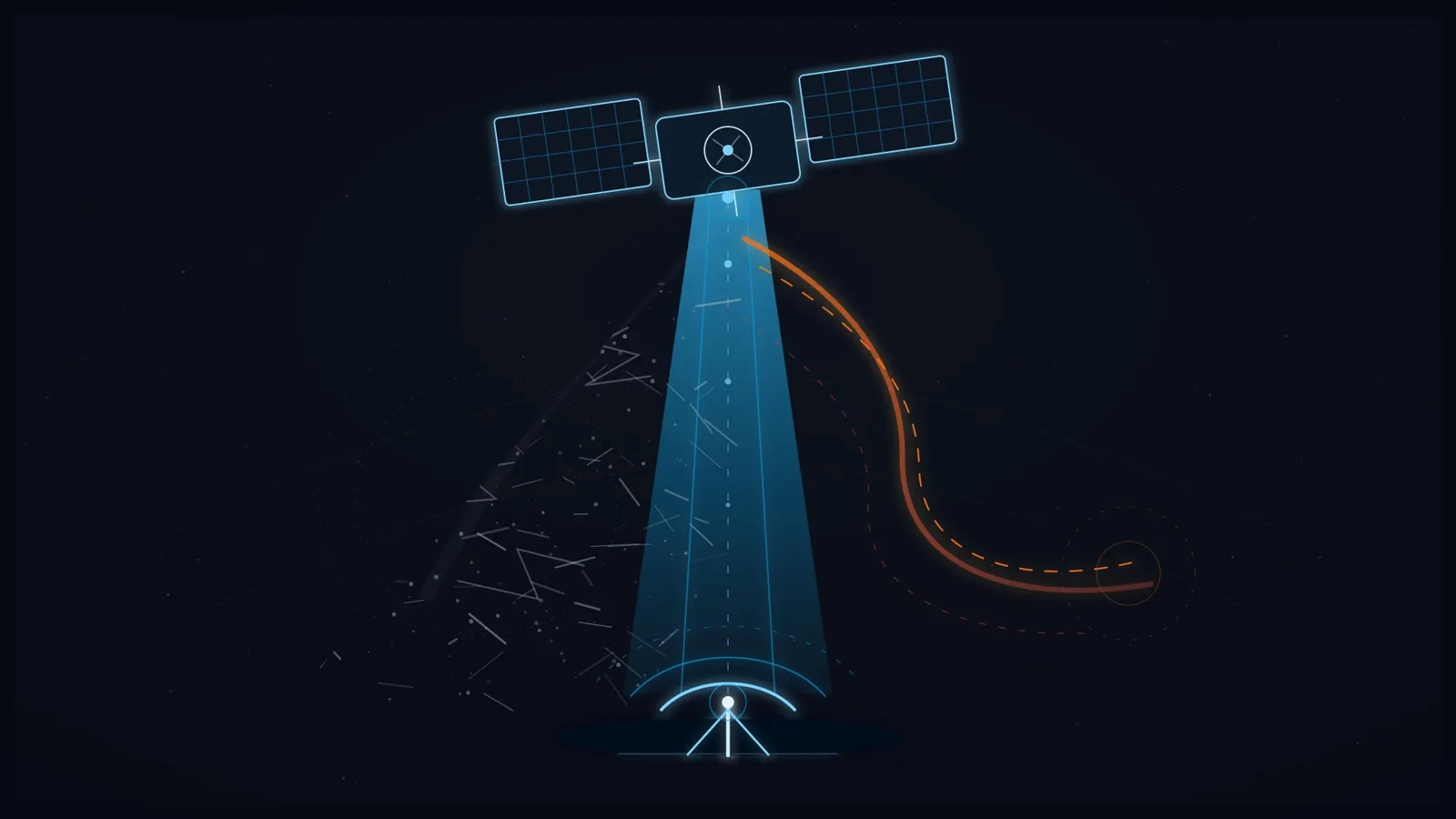
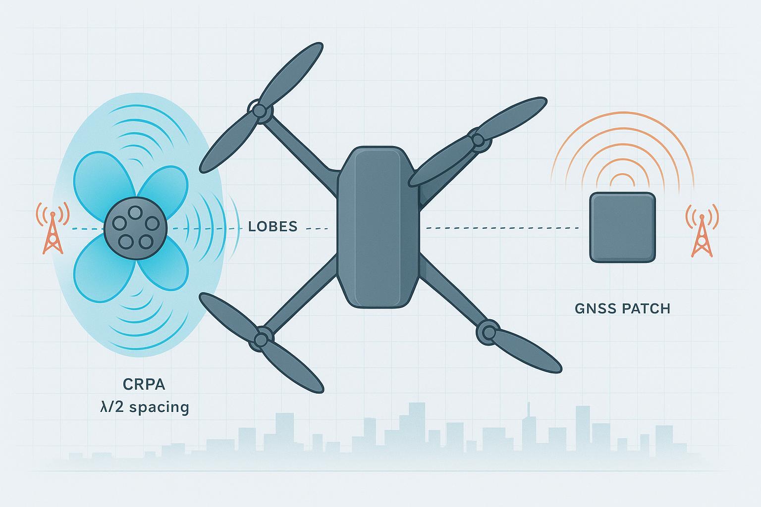
What a CRPA does: Multiple antenna elements feed a beamforming processor to enhance signals from desired directions and place deep nulls toward interferers. With N elements, you typically get about N−1 degrees of freedom for independent interference suppression while maintaining gain toward satellites. A concise overview sits in the encyclopedia entry on the topic: see the Controlled Reception Pattern Antenna article in Wikipedia (2026), which explains beamforming, null‑steering, and multi‑source handling under “CRPA.” The fundamentals and N−1 rule of thumb are documented there: Wikipedia — Controlled Reception Pattern Antenna.
-
Why spacing matters: Arrays sized for UAVs usually target ~λ/2 element spacing (∼20 cm at L1), which drives a practical top‑deck diameter of ~200–250 mm—often the first integration hurdle.
-
Single‑element reality: A single patch/helical/microstrip has no spatial selectivity; resilience depends on good RF hygiene (filters, shielding) and receiver firmware. That’s fine in benign RF, fragile when jammers or spoofers show up.
-
Testing methods you can trust: Zoned chambers and wavefront simulators let you quantify CRPA null depth and RTK behavior repeatably. Methodology and pitfalls are outlined in the engineering articles from test vendors like Spirent—see the 2024–2026 technical blog “CRPA Antennas Explained — choosing and testing anti‑jam solutions,” which describes wavefront testing and evaluation factors: Spirent — CRPA Antennas Explained. Safran’s testing guides also emphasize synchronized jamming and spatial filtering assessment for CRPA validation: Safran Navigation & Timing — An Engineer’s Guide to CRPA Testing.
Why this matters for RTK on UAVs
RTK is unforgiving to lost epochs and cycle slips. In contested or just “messy” RF, two things decide whether you complete the mission:
-
How much interference you can suppress before the receiver loses track of enough satellites to drop from fixed to float or no‑fix.
-
How quickly ambiguities reconverge to fixed after a disturbance.
In lab wavefront sims, our typical script is a three‑threat profile: one CW near L1, one chirp across L1/L2, and a low‑elevation spoofing source. With a high‑grade single element, the fix ratio over a 20‑minute profile fell to ~62–70% depending on cable/EMI quality. A 4‑element CRPA, calibrated, pushed that to ~88–92%. A 7‑element CRPA, properly calibrated and thermally stabilized, cleared ~95%+ with nulls steered at the active interferers. Numbers move around with geometry, power, and calibration—but the pattern holds: spatial filtering buys you margin.
For field context, we correlate RTK fix ratio with C/N0 histograms and residuals. In high‑multipath approaches (steel catwalks near tanks), the CRPA’s shaped pattern shaved down low‑elevation reflections enough to reduce cycle‑slip bursts. A good single element on a proper ground plane was close in calm RF but faltered when a drive‑by jammer spiked.
Head‑to‑head: CRPA vs single‑element antenna (UAV RTK focus)
Below, “indicative” means representative of 2024–2026 UAV‑sized systems when properly integrated and calibrated; verify with your vendors and your testbed.
Dimension | CRPA (4–7 elements) | Single‑element (patch/helical/microstrip) |
|---|---|---|
Anti‑jam effectiveness | J/S improvement ~20–40 dB indicative; multiple simultaneous nulls (DoF≈N−1) when calibrated | No spatial filtering; relies on filtering/firmware; vulnerable to strong narrowband/wideband jammers |
Null depth | ~30–50 dB indicative nulls toward interferers (calibrated, band‑dependent) | N/A (single main lobe; no steerable nulls) |
RTK availability under RFI | 88–95%+ fix ratio typical in scripted lab threats (integration dependent) | 50–80% fix ratio typical under the same threats (high variance) |
Multipath rejection | Beam shaping can attenuate low‑elevation reflections | With a solid ground plane/choke, can be competitive in benign scenes |
SWaP & integration | 300–600 g array + processor; ~200–250 mm dia; ~5–15 W | 15–60 g; small footprint; <<1 W |
Calibration & upkeep | Requires array manifold calibration; re‑checks after mechanical/thermal shocks | Largely set‑and‑forget once mounted and shielded correctly |
Receiver/firmware fit | May need paired processor or multi‑RF inputs; integration path varies | Works with mainstream RTK receivers out of the box |
EMI/grounding & cabling | More cables/connectors; good harnessing essential | Simpler harness; still sensitive to poor grounding or noisy ESCs |
Cost/TCO (indicative 2026) | Often 10×–50× vs single‑element including processor + testing | ~$100–$800 typical per antenna |
Certification/readiness | UAS approvals evolving; no dedicated CRPA MOPS yet per RTCA | Mature for commercial UAVs |
Evidence anchors: degrees of freedom and CRPA basics per Wikipedia — Controlled Reception Pattern Antenna; test methodology per Spirent — CRPA Antennas Explained and Safran — CRPA Testing Guide. For certification outlook, RTCA SC‑159 noted the lack of a specific CRPA MOPS in public 2024–2026 summaries: see RTCA — SC‑159 summaries (2024–2026).
Best‑for scenarios (how to choose)
-
High‑threat or near‑border operations: If your risk model includes multiple jammers/spoofers or frequent RFI incidents, prioritize a 4–7 element CRPA. The N−1 degrees of freedom let you suppress several threats at once while keeping gain to satellites.
-
Industrial RFI corridors and dense urban: If you see intermittent chirps and harmonics from machinery or repeaters, CRPA’s spatial filtering noticeably improves the fix ratio. If budgets are tight, at least design a CRPA‑ready top deck and power path.
-
Benign rural mapping and agriculture: A single‑element antenna on a proper ground plane maximizes flight time and simplicity. Spend effort on clean EMI layout and good coax/connectors.
-
SWaP‑constrained small drones (<250 g payload headroom): Stick with a high‑quality single‑element and stack software mitigations (advanced notch filters, multi‑band tracking, INS aiding). You can still pre‑provision for future CRPA with a removable top plate and spare power lead.
-
Retrofit pilots: When you’re unsure, flight‑test both on the same airframe. Keep the mounting template sized for ~220–250 mm so a CRPA can drop in later without re‑CFD of the fuselage.
Common engineering mistakes that tank RTK in tough RF
-
Mounting the antenna off‑center or too close to carbon structures, then blaming the receiver. Even a few centimeters of shadowing at low elevation angles raises cycle‑slip rates.
-
Skipping a proper ground plane (single‑element) or compressing array diameter below ~λ/2 (CRPA), which cripples pattern control.
-
Treating CRPA as plug‑and‑play: no manifold calibration, no thermal soak, no post‑mount validation flights.
-
Routing GNSS coax alongside high‑current ESC leads or telemetry radios, creating conducted and radiated self‑noise that looks like “mystery RFI.”
-
Ignoring receiver firmware release notes on anti‑jam/spoofing features and RTK filter behavior during null‑steering events.
Practical improvement checklist you can implement this week
-
Selection: If you expect two or more concurrent interferers above ~20 dB J/S, shortlist a CRPA (4–7 elements). Otherwise, choose a dual‑/tri‑band single‑element with documented PCO/PCV and low axial ratio.
-
Mounting template: Reserve a circular keep‑out of 200–250 mm on the top deck for future CRPA; for single‑element, provide ≥λ/4 ground plane (≈9–10 cm at L1) in metal or metallized composite.
-
Shielding and grounding: Star‑ground architecture; bond the ground plane to the airframe reference; use ferrites near radios; isolate noisy DC‑DC converters.
-
Cabling: Use low‑loss coax with known insertion loss; route away from power harnesses; torque SMA/MMCX to spec; strain‑relief every 10–15 cm.
-
Firmware and receiver settings: Enable anti‑jam features (adaptive notch, interference monitors); log fix status, C/N0, residuals, and ambiguity states at ≥5 Hz during trials.
-
Validation: Run a repeatable flight script and a rooftop test with a legal, controlled interferer or a chamber session; collect fix‑ratio vs time, convergence times, and cycle‑slip counts for before/after comparisons.
Pricing and procurement notes (indicative, 2026)
Plan budgets, not guesses. High‑quality single‑element UAV antennas typically land in the ~$100–$800 band depending on frequency coverage and grade. CRPA solutions—array plus processing—often total 10×–50× that on a TCO basis once you include calibration, validation testing, and any airworthiness paperwork. Prices move with export rules and options, so get current quotes. For UAV‑suitable SWaP examples and integration considerations, vendors like Hexagon/NovAtel describe airborne anti‑jam units (e.g., GAJT series) with form‑factor and latency notes that matter for integration. Some compact solutions aimed at drones discuss maintaining lock under strong interference in marketing explainers; treat such claims as scenario‑specific and verify in your testbed, e.g., Infinidome — What is a CRPA Anti‑Jamming Antenna?.
On approvals, the standards community has acknowledged gaps. RTCA SC‑159 meeting notes in 2024–2026 mention there’s no dedicated CRPA MOPS yet for aviation use; plan for additional documentation and program risk if you’re pursuing formal approvals. Reference: RTCA — SC‑159 summaries (2024–2026).
Key takeaways
-
CRPA vs single‑element antenna isn’t about “better,” it’s about margin under interference. If your routes see real jammers/spoofers, spatial nulling is often the only way to keep RTK fix reliably.
-
SWaP and integration are real: λ/2 spacing pushes you to ~20+ cm diameters and 5–15 W power budgets. Design CRPA‑ready even if you don’t buy it on day one.
-
A single‑element, well‑mounted with clean EMI practice, still wins for benign airspace and small craft. Don’t shortchange the ground plane and harnessing.
-
Validate with wavefront/chamber methods and repeatable field scripts; don’t ship based on a single sunny‑day flight.
FAQ
How many interferers can a UAV‑sized CRPA handle?
As a rule of thumb, an N‑element array provides about N−1 degrees of freedom for independent nulls while maintaining gain to satellites. A 6‑element array can typically form up to five deep nulls, subject to calibration and geometry. See the concept summary in Wikipedia’s Controlled Reception Pattern Antenna article for the underlying beamforming principle.
How much anti‑jam improvement should I expect over a single element?
Treat 20–40 dB J/S improvement and ~30–50 dB null depths as indicative ranges for calibrated 4–7 element arrays. Actual performance depends on array geometry, calibration quality, thermal stability, and the interference profile. Verify in a wavefront simulator or zoned chamber such as those discussed by test vendors (e.g., Spirent’s CRPA testing overview).
How long does CRPA calibration take, and how often is it needed?
Plan a few hours for initial manifold calibration and post‑mount validation, plus additional time after significant mechanical changes or thermal/vibration events. Many teams schedule a quick self‑check at each major maintenance interval and a full calibration if any structural changes occur. Method guidance appears in Safran’s CRPA testing resources.
Can small drones (<250 g extra payload) use CRPA effectively?
It’s challenging. Arrays sized for λ/2 spacing at L1 push you toward ~200 mm diameters and hundreds of grams plus several watts. For micro‑UAVs, a single‑element with meticulous EMI control and software mitigations (adaptive notch, multi‑band, INS aiding) is usually the pragmatic path—while designing the fuselage to accept a larger top plate on future variants.
What’s the cleanest retrofit path if I start single‑element now?
Make the platform CRPA‑ready: reserve a 200–250 mm circular keep‑out on the top deck; leave a spare 28 V (or vendor‑required) power line with 15 W headroom; route an Ethernet/USB line to the avionics bay; and pick a receiver that can accept either a combined RF feed from a CRPA processor or multiple RF inputs. Run baseline flight scripts now so you have apples‑to‑apples data after the upgrade.
Methods and further reading: CRPA fundamentals and DoF are summarized in Wikipedia — Controlled Reception Pattern Antenna. For test and evaluation practices, see Spirent — CRPA Antennas Explained and Safran Navigation & Timing — CRPA testing guide. Regulatory outlook and MOPS status are discussed in RTCA — SC‑159 public summaries, 2024–2026.