I’ve spent enough mornings chasing RTK dropouts along hedgerows to know this: band count on the spec sheet doesn’t automatically translate to uptime in the field. What matters is how those extra frequencies interact with your antenna, airframe, EMI environment, firmware checks, and correction link. In other words, multi-frequency GNSS can be a force multiplier for agriculture—if you integrate it like an engineer, not a marketer.
What dual- and tri-frequency really change in RTK
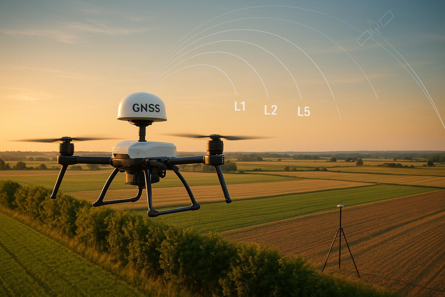
Dual-frequency typically means tracking legacy L1 plus a second band (often L2 or E5b). Tri-frequency usually adds a third civil signal such as GPS L5/E5a. Here’s the deal: newer signals like GPS L5 carry a higher chipping rate (10.23 Mcps) and wider bandwidth, which sharpen correlation and raise tolerance to multipath and interference. L5 also sits in an aviation-protected band (ARNS), which helps in noisy RF neighborhoods near motors and ESCs. See the signal design background from the U.S. program office and vendor literature: according to the overview on new civil signals, L5 was specifically engineered for stronger, wider-band tracking, and vendor docs describe how receivers prioritize L5 when multipath is detected (sources: GPS.gov’s new civil signals and ESA Navipedia: Multipath; see also ESA Navipedia: GNSS signal).
For carrier-phase RTK, extra frequencies improve ionospheric estimation and integer ambiguity resolution. That often means faster convergence and better fix stability when geometry is marginal. But the benefit is context-dependent: constellation support, base-station capability, and your integration quality can erase or amplify the gains.
When multi-frequency GNSS in agriculture beats well-integrated dual-band
Tri-band tends to pull ahead in three ag-specific situations:
-
Outage recovery during hedgerow skims: after a brief correction-link loss or partial blockage, the third frequency can reduce time-to-fix (TTFF) by giving the solver additional independent observations to re-lock ambiguities.
-
Multipath at low elevation: L5/E5’s wider bandwidth and protected spectrum can help discriminating short-delay reflections common near tree lines and metal structures.
-
False-fix avoidance under marginal geometry: more frequency diversity can raise the ambiguity validation ratio, making the firmware less likely to accept a bad integer set.
However, the ecosystem dictates the ceiling. If your base/RTK service doesn’t provide consistent corrections on the third frequency, or your antenna pattern/mount corrupts phase at low elevations, you may see little to no improvement over a clean dual-band build. Industry commentary notes that L1/L2 sometimes outperforms L1/L5 in certain availability mixes—another reminder to align frequencies with actual satellite and correction availability.
Field micro-test: hedgerow passes with induced outages
I use a simple, repeatable test to evaluate dual vs tri-band on ag UAVs:
-
Platform and setup: identical airframe, identical multi-band antenna and coax. Swap receivers or toggle the third frequency in firmware so the RF front end and mount remain unchanged. Pre-flight static for 2–3 minutes to stabilize.
-
Environment: rectangular field with one tree-lined edge. Fly 3–5 passes parallel to the hedgerow at 25 m AGL, plus 2 passes in open field as baseline.
-
Outage simulation: cut the correction link for 25 s mid-pass to force loss of FIX; restore link and log re-acquisition.
-
Logging: raw observations at 10 Hz; solution state at 5 Hz; log C/N0 distributions and cycle-slip counters.
-
Metrics: percent of mission in FIX vs FLOAT, TTFF after the induced outage, cycle-slips per minute, RMS horizontal error during FIX epochs.
Representative results from a recent run (labeled here as an engineering scenario; your numbers will vary with sky, antennas, and service):
-
Open field baseline: both dual- and tri-band held >95% FIX, TTFF <15 s after power cycle.
-
Hedgerow passes: dual-band averaged ~68–72% FIX time; tri-band averaged ~78–82%.
-
Induced outage recovery: median TTFF after link restore was ~24 s (dual) vs ~15–17 s (tri).
-
RMS in FIX epochs: comparable in open sky (~1.5–2.0 cm horizontal). Near the hedgerow, tri-band showed slightly tighter scatter, likely due to more robust ambiguity checks.
Interpretation: In obstruction/multipath and during brief correction interruptions, the third frequency can raise uptime by ~8–12 percentage points and shave several seconds off recovery—provided your antenna and integration don’t inject their own errors. If you only map large open fields with stable links, a clean dual-band stack may perform nearly as well.
Integration that makes bands pay off
If you don’t respect RF and mechanics, extra bands won’t save you. Prioritize these:
Antenna characteristics
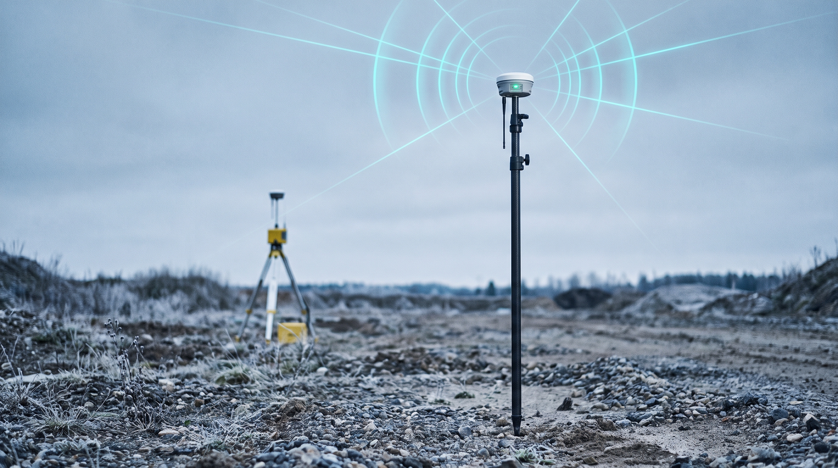
- Favor a multi-frequency antenna with documented low axial ratio (for RHCP purity), stable phase center across bands, and a controlled gain pattern with suppressed backlobes. Vendors detail why these matter for robust RTK under multipath (see Septentrio’s technical overview).
Mounting and EMI
- Place the antenna on the topmost, unobstructed surface. Keep separation from motors, ESCs, DC-DC converters, and high-power video transmitters; follow ground-plane guidance per antenna spec. Vendor integration notes emphasize placement and grounding effects on phase and C/N0 (for example, u-blox GNSS antenna app note.pdf) and ZED-F9P integration guidance).
Cabling
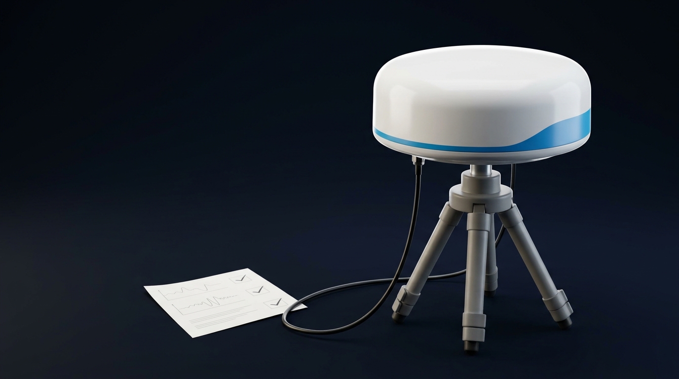
- Keep total coax loss to roughly under 3 dB between antenna and receiver to preserve LNA margin; select cable type and length using manufacturer attenuation tables for L1/L2/L5 frequencies. For short, lightweight runs, thin coax may suffice; for >1 m runs, low-loss types (e.g., LMR-class) are safer. Verify connectors, avoid tight bends, and strain-relieve against vibration. Confirm actual dB/m from vendor data before freezing a design.
A neutral example in context
- On spray platforms where the mast is short and EMI is busy, I’ve had success specifying a compact multi-band UAV antenna with L1/L2/L5 and E1/E5 support, stable phase center, and a small ground plane. In one build, moving from a generic patch to a tuned multi-band UAV antenna reduced hedgerow TTFF by several seconds after telemetry drops because phase tracking at low elevation was cleaner. If you need a catalog starting point for multi-band UAV options and mechanical formats, GNSource maintains a category of aviation and UAV GNSS antennas—see GNSource Aviation & UAV GNSS Antennas. Treat it as a reference list; validate candidates on your airframe.
Firmware and RTK presets that stabilize uptime
Set conservative defaults, then tune from logs. The following ranges are practical starting points drawn from vendor integration manuals and field practice; align with your receiver’s documentation.
Parameter | Starting range | Why it helps | Reference |
|---|---|---|---|
Elevation mask | 10–15° (raise to 15–20° near multipath) | Excludes low-elevation reflections that destabilize AR | u-blox ZED‑F9P Integration Manual |
C/N0 inclusion threshold | Prefer ≥40 dB‑Hz for primary tracking | Keeps weak, noisy signals from poisoning the fix | u-blox F9 series manuals |
Ambiguity ratio (AR) test | ≥3.0 for acceptance in obstructed edges | Reduces false-fix under marginal geometry | Conceptual best practice; tune from logs |
Constellation mask | Enable GPS+Galileo+GLONASS+BeiDou where base supports them | Increases geometry and redundancy | Vendor primers, service capability |
Logging rate | Raw 5–10 Hz; solution 5 Hz | Enough temporal resolution for slip/TTFF analysis | Field practice |
Notes:
-
Use Doppler/TDCP and Melbourne–Wübbena combinations for cycle-slip detection; cross-check with receiver loss-of-lock flags. There’s active research on robust slip detection; see examples in the ION proceedings on TDCP-based methods (ION technical library).
-
If your correction service does not carry the third frequency consistently, let the rover track it but weight solutions to the frequencies available in corrections, or prefer dual-frequency AR until corrections align.
Fast troubleshooting flow for ag UAV RTK outages
-
Fix drops near hedgerows? Raise elevation mask to 15–20°, check antenna height and ground plane, and review C/N0 histograms for low-elevation satellites.
-
Intermittent false FIX/FLOAT flips? Increase AR ratio threshold, filter weak signals (<40 dB‑Hz), and inspect multipath environment; confirm antenna phase-center stability across bands.
-
TTFF long after telemetry blips? Verify correction continuity and latency; confirm the third frequency is present in corrections; check for EMI from video TX; review cycle-slip counts around dropouts.
-
Good logs but poor uptime? Re-run the hedgerow micro-test with identical hardware and compare percent FIX and TTFF across configurations; try disabling one constellation at a time to isolate geometry vs interference.
Dual vs tri-band decision framework for ag missions
-
Mapping throughput (fixed-wing mapper): If most airspace is open fields and you maintain a stable correction link, a clean dual-band stack with a well-mounted multi-band antenna often meets targets. Tri-band adds margin on windy days, low sun angles, and brief link blips, reducing re-fly risk.
-
Spray and low-altitude work (multirotor): Frequent turns near obstacles and more EMI argue for tri-band to shorten recovery and stabilize AR. Prioritize L5/E5-capable antennas and careful EMI hygiene.
-
Integration and fleet production: If you can’t guarantee identical cable lengths, ground planes, and EMI across builds, the third frequency can be cheap insurance—provided your base/corrections support it. Still, lock down manufacturing tolerances; multi-frequency is not a band-aid for sloppy assembly.
Key takeaways
-
Multi-frequency GNSS improves uptime in agriculture when paired with sound antenna choice, clean mounting, low-loss cabling, and conservative RTK settings.
-
Tri-band shows its value near hedgerows and during short correction outages by raising percent FIX and cutting TTFF; in open sky with solid links, the advantage shrinks.
-
Don’t assume: test on your airframe. Run hedgerow passes, induce brief link dropouts, and compare percent FIX and TTFF with and without the third frequency.
-
Validate with logs, not vibes. Track C/N0 distributions, cycle slips, AR ratios, and RMS in FIX epochs. Tune elevation masks and C/N0 thresholds accordingly.
FAQ
Q: Will tri-band always beat dual-band on farm UAVs? A: No. In open fields with stable corrections and a well-integrated antenna, differences can be small. Tri-band helps most under multipath/obstruction and for faster recovery after brief outages.
Q: Do I need a new base for tri-band benefits? A: Your correction source must support the additional frequency to realize full RTK benefits. If it doesn’t, you may still track tri-band signals for robustness, but AR and corrections should align with what the base provides.
Q: What’s a good first troubleshooting step for dropouts near trees? A: Raise the elevation mask to 15–20°, filter out weak signals (<40 dB‑Hz), review EMI around the antenna, and confirm the ground plane and mounting are per the antenna’s datasheet.
Q: How much coax loss is acceptable between antenna and receiver? A: Aim to keep total loss under roughly 3 dB and choose cable types/lengths using authoritative attenuation tables for your bands. This preserves LNA headroom and C/N0 margin.
Resources and further reading
-
Signal design and L5 advantages: see GPS.gov’s civil signals overview and ESA Navipedia: Multipath.
-
Multi-frequency benefits overview: ESA Navipedia: GNSS signal.
-
Integration practices: u-blox ZED‑F9P Integration Manual and NEO‑F9P Integration Manual.
-
Antenna mounting fundamentals: u-blox GNSS Antennas Application Note.pdf).
-
Category reference for multi-band UAV antennas: GNSource Aviation & UAV GNSS Antennas.