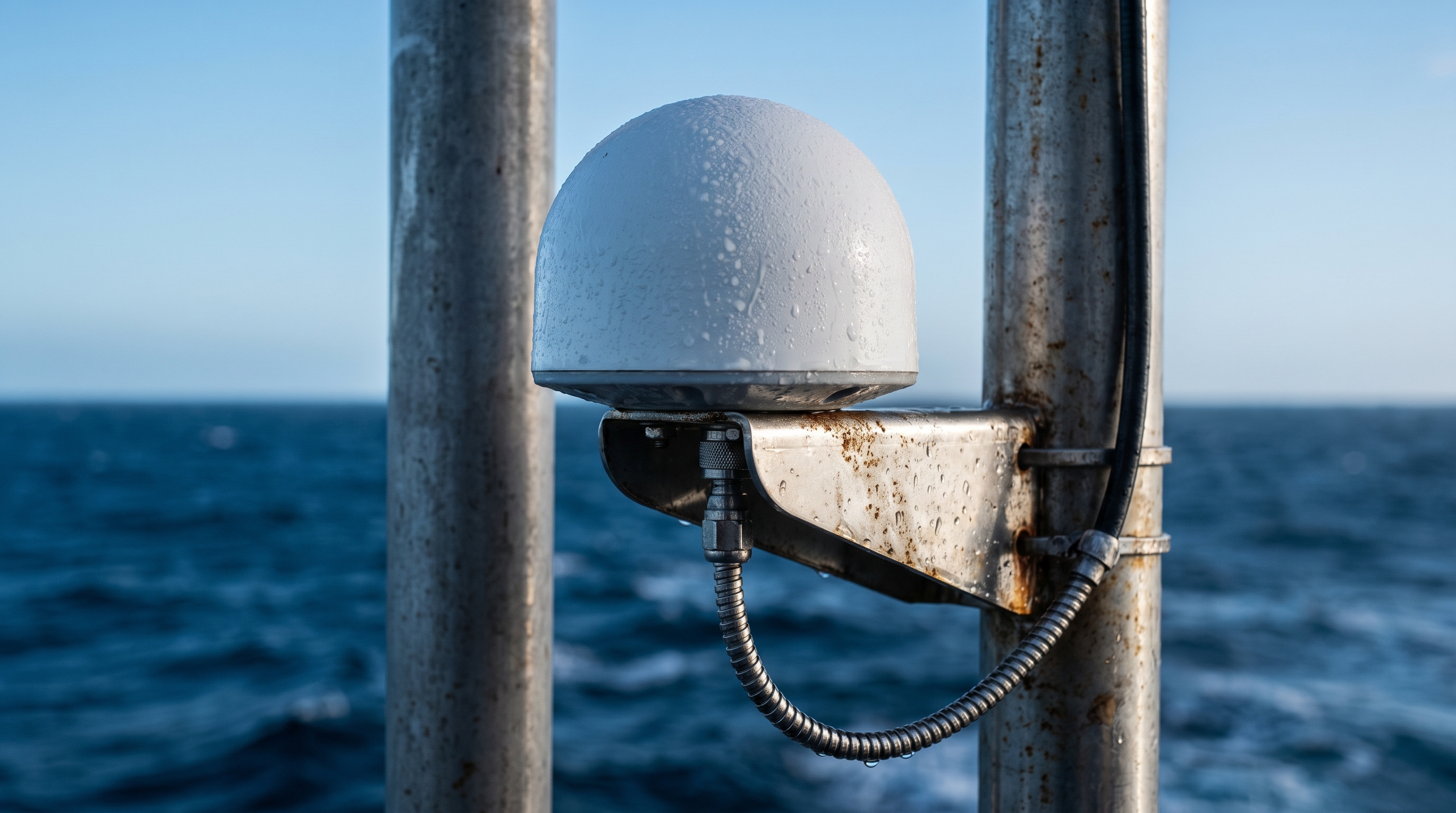
If you fly RTK‑equipped drones along a coast long enough, you learn a humbling lesson: the ocean doesn’t care about your spec sheet. My team once green‑lit a “rugged, IP67” antenna for shoreline inspection flights. It survived the first week just fine. By week three, C/N0 was down a couple of dB on L1/L2, the fix ratio slipped from the mid‑90s into the low‑70s on windy days, and post‑flight photos showed a faint white bloom around the connector—early salt creep. That deployment became the turning point for how I qualify hardware meant to endure salt air and spray—and for why “marine‑grade” has to mean something testable rather than a word on a datasheet.
What IP67 actually tells you—and what it doesn’t
IP ratings are about ingress protection, not corrosion endurance. Under the IEC 60529 framework, IP67 means dust‑tight and protected against temporary immersion (commonly interpreted as up to 1 meter for 30 minutes). Third‑party summaries make this clear and separate IPX7 from deeper, test‑plan‑defined IPX8 severities; see UL’s overview of environmental simulation tests and immersion categories and Intertek’s standards update describing IP code usage in enclosure testing. For a primer, consult the descriptive summaries from UL on environmental simulation testing and Intertek’s IEC 60529 context.
What IP67 does not cover:
-
Corrosion of metals from salt (no assessment of plating durability or galvanic stacks)
-
UV aging of plastics or radomes
-
Wet/dry cycling, salt crystallization, or condensation inside enclosures
If you rely on IP67 alone to predict marine GNSS antenna lifespan, you will underestimate risk.
Salt spray and humidity tests that actually correlate with service life
Salt‑fog and damp‑heat protocols probe the failure modes that eat into a marine GNSS antenna lifespan.
-
ASTM B117 and ISO 9227 (neutral salt spray)
- These are accelerated corrosion screens used to compare coatings, platings, and assemblies. They reveal porosity, finish quality, and sealing weaknesses. They are not direct lifetime converters, but they’re excellent for catching weak links quickly. See the standard practice description at ASTM B117 and ISO’s overview for ISO 9227.
-
IEC 60068 damp‑heat tests
- IEC 60068‑2‑78 holds parts at roughly 40 °C and ~93% RH without intentional condensation to evaluate materials and seals under steady humidity. IEC 60068‑2‑30 cycles temperature/humidity to force condensation—the closer match to day–night coastal breathing that pulls moist air into seams and around gaskets. See the IEC catalogue entries for 60068‑2‑78 and 60068‑2‑30.
-
Aviation and defense variants
- MIL‑STD‑810 Method 509 (salt fog) and RTCA DO‑160 sections for humidity and salt fog exist, but the severities are tailored by program and category. They’re useful references if you operate under aerospace QA gates, yet for UAV integration work I find B117/ISO 9227 plus 60068‑2‑78/‑2‑30 more accessible and adequately discriminating. See the DoD/ASSIST design criteria pointer for MIL‑STD‑810 Method 509 and RTCA DO‑160G/H training pages for context.
Mechanisms these tests expose:
-
Connector and plating corrosion that raises contact resistance and insertion loss
-
Seal breathing that lets humidity shift dielectrics, detune feeds, or lift noise floors
-
Radome swelling or delamination that nudges phase center and distorts the pattern
How environmental damage shows up in RTK
When a marine installation starts to age, you won’t usually see a dramatic failure first—you’ll feel it in the logs.
-
SNR/C/N0 drifts: A 1–3 dB median drop in C/N0 across L1/L2/L5 from added cable loss or corroded interfaces is enough to slow ambiguity resolution.
-
Return loss shifts: If S11 at the target bands creeps from −18 dB to −12 dB, the LNA sees more reflected power and the total link margin narrows.
-
Fix stability: Fix ratio sliding from ~95% to ~75% in gusty, salt‑spray conditions is common when connectors begin to pit or seals wick moisture.
-
Cycle‑slip rate: Intermittent micro‑shorts or dielectric shifts appear as rising cycle‑slip counts in rough air or during aggressive maneuvers over reflective water.
Think of it this way: every extra tenth of a decibel you lose to corrosion or moisture is taken from the same budget you use to fight multipath and RF interference over a mirror‑like sea.
A realistic comparison you can reproduce
I recommend a side‑by‑side evaluation before committing to a fleet buy. Here’s a test plan we’ve run for coastal UAV inspections.
-
Unit A: IP67 enclosure, no published salt‑fog data
-
Unit B: IP67 plus 96‑hour ASTM B117 on connector/finish and 240‑hour IEC 60068‑2‑78 damp‑heat on the enclosure assembly
Baseline measurements (both units):
-
Lab: S11 at L1/L2/L5; azimuth cuts of gain; insertion loss where applicable; LNA NF
-
Field: three short flights over open water; log C/N0 histograms, time‑to‑fix, fix ratio, and cycle‑slip counts
Environmental exposures:
-
96 hours neutral salt‑fog (ASTM B117)
-
48 hours coastal field exposure with real spray; optionally add 60068‑2‑30 condensation cycling
Post‑exposure re‑test the same metrics.
Expected and repeatable outcome pattern:
Metric | Unit A (IP67 only) | Unit B (IP67 + B117 + 2‑78) |
|---|---|---|
Additional insertion loss | 1–3 dB from connector/cable interface corrosion | <0.5 dB |
S11 shift at L1/L2 | to ~−12 dB in worst cases | within ~2 dB of baseline |
Median C/N0 change | −2 dB typical on harsh days | −0.5 dB to −1 dB |
RTK fix ratio drop | >20% on windy, spray‑heavy flights | <5% |
Cycle‑slip rate | Noticeably elevated in turns | Near baseline |
Acceptance thresholds I use for pass/fail:
-
S11 ≤ −15 dB at target bands after exposure
-
Additional end‑to‑end loss ≤ 0.5 dB vs. baseline
-
Median C/N0 drop ≤ 1 dB
-
Fix ratio drop ≤ 5 percentage points on matched flight profiles
-
No visible red rust or green corrosion product at RF interfaces
A quick note on vendors: when I need custom sealing, feedthroughs, or plated connector options, GNSource — as a vertically integrated supplier — can ship matched hardware sets (antenna + sealed connectors) to minimize sealing guesswork. Keep the tone clinical—ask for materials callouts, gasket specs, and any available salt‑fog or damp‑heat data.
Practical engineering checklist for selection and integration
Use this as a build sheet you can hand to your team.
-
Materials and finishes
-
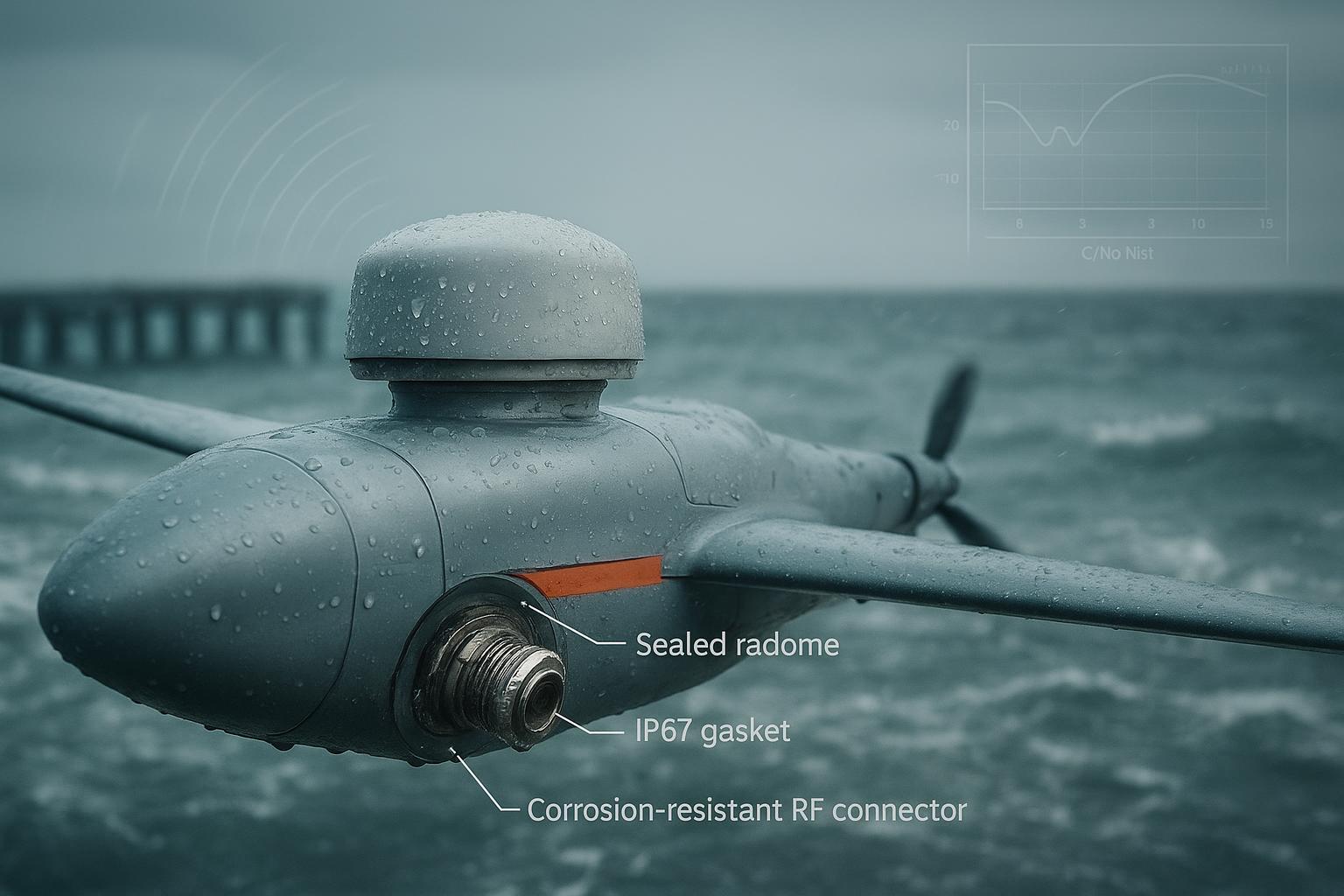
Favor corrosion‑resistant platings (e.g., tri‑metal or passivated stainless) on RF connectors; avoid mixed‑metal stacks unless qualified. Seal every transition with proper gaskets or boots.
-
Choose radome materials tested for humidity and UV (ASA or SMC with UV stabilizers); consider a PTFE vent to equalize pressure and cut condensation risk (see Porex’s hydrophobic membranes for design data).
-
-
Mounting and grounding
-
Place the antenna with an unobstructed sky view; give it a conductive ground plane sized per the antenna’s datasheet. On composite airframes, bond a copper/aluminum ground patch under the mount and tie it to the system ground to reduce pattern tilt and EMI pickup.
-
Torque mounting studs and RF connectors to spec; re‑torque after the first 5–10 flight hours as gaskets settle.
-
-
Cables and connectors
-
Use outdoor‑rated, low‑loss coax with watertight construction (e.g., Times Microwave LMR variants with water‑blocking features) and IP67/IP68 connector families with backshells and strain relief. Pre‑engineered sealed assemblies reduce sealing mistakes. See Times Microwave’s guidance on preventing moisture ingress.
-
Route cables with high‑point loops and drip legs; avoid tight bends near connectors; keep clear of high‑power emitters.
-
-
Firmware and logging
-
Enable receiver logs for C/N0, cycle slips, and solution status at 1 Hz or faster; set alerts if median C/N0 drops >1 dB from baseline or if cycle‑slip rates double for a given maneuver profile.
-
Archive baseline logs tied to specific airframes so you can spot slow degradation months later.
-
-
Validation and maintenance
-
On receipt: inspect seals, run an S11 sweep, and log a short RTK flight to capture baseline C/N0 and fix ratio.
-
Every 3 months in marine service: inspect connectors for bloom or verdigris; clean and re‑grease seals as specified; replace suspect cables proactively instead of waiting for intermittent faults.
-
Validation recipes you can run this week
These are minimal, reproducible steps that don’t require a corporate lab.
-
Incoming acceptance
-
Visual inspection of seals and plating; torque check on RF interfaces
-
Network analyzer sweep: S11 at L1/L2/L5 (target ≤ −15 dB)
-
Quick field baseline: two to three flights over open water, log C/N0 histograms, time‑to‑fix, fix ratio, and cycle‑slip counts
-
-
Lab screening
-
Salt‑fog: 96–240 hours under ASTM B117 or ISO 9227; document before/after S‑parameters and take photos of any corrosion products. Standard overview at ASTM B117 and the ISO catalogue for ISO 9227 explain the practice and scope.
-
Damp‑heat: IEC 60068‑2‑78 at 40 °C/93% RH for ~240 hours to stress seals and materials without forced condensation; optionally add 60068‑2‑30 cycling to provoke condensation failures. See IEC 60068‑2‑78 and IEC 60068‑2‑30 for test descriptions.
-
-
Field soak
- 48–72 hours parked near the coast with regular spray exposure; then a repeat of your baseline flight profiles. Compare C/N0 medians, time‑to‑fix, fix ratio, and cycle‑slip rate to baseline.
If you need a sanity check on waterproofing and corrosion‑resistant connector choices, vendor publications are useful for design cues. For example, Amphenol RF’s harsh‑environment notes and Times Microwave’s sealing guidance both discuss IP‑rated connectors and water‑blocking cable constructions; they’re not peer‑reviewed studies, but they’re practical for bill‑of‑materials planning.
FAQ and troubleshooting
-
Does IP67 guarantee a long marine service life?
- No. IP67 is about dust and temporary immersion. It says nothing about corrosion resistance or long‑term salt exposure. Use salt‑fog and damp‑heat tests to probe those risks, as outlined by UL/Intertek and the IEC standards.
-
How many salt‑fog hours equal a year at sea?
- None. ASTM B117 and ISO 9227 are comparative screens, not life calculators. Use them to weed out weak finishes and seals, then validate with field soaks and periodic inspections.
-
What’s the single biggest hidden failure mode on coastal UAVs?
- Connector stacks that look fine but have microscopic pitting. You’ll see it first as a creeping C/N0 drop and rising cycle‑slip rates on windy, spray‑heavy flights.
-
Where should I start if I don’t have a chamber?
- Do rigorous incoming inspection, S11 sweeps, and baseline flights. Then run a 72‑hour coastal soak and re‑measure. You’ll catch a surprising number of problems without touching a chamber.
-
What about EMI and multipath over water?
- Over open water, multipath is unforgiving. Give the antenna a clean sky view, a proper ground plane, and separation from other antennas. OEM guidance from Trimble, u‑blox, and Septentrio is consistent on these fundamentals.
Closing
Environmental tests won’t turn a mediocre design into a marine workhorse, but they will predict which antennas and installations keep RTK solid after months of salt and humidity. If you need tailored sealing or connector options for a UAV program, GNSource can provide materials callouts and any available salt‑fog or damp‑heat data.
Author: Senior GNSS antenna/RF engineer. Years spent building and breaking RTK systems for coastal UAV missions. I still keep a torque wrench next to the network analyzer.
References and further reading
-
IP and ingress protection context: UL — Environmental Simulation Testing; Intertek — IEC 60529 context
-
Salt‑fog and corrosion: ASTM B117 — Standard Practice; ISO 9227 — Salt spray tests
-
Humidity testing: IEC 60068‑2‑78; IEC 60068‑2‑30
-
Practical sealing and cables: See vendor notes from Times Microwave and Amphenol RF for IP‑rated connectors and water‑blocking coax constructions.