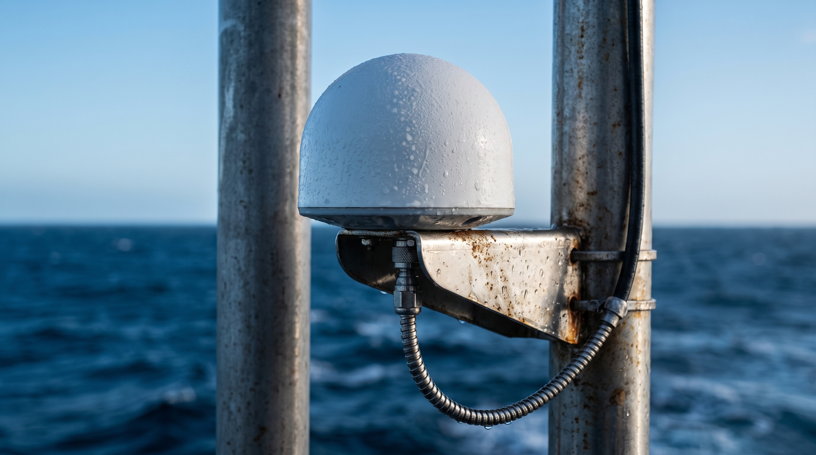
On one of my first offshore RTK jobs, a small USV kept dropping from fixed to float every few minutes. The culprit wasn’t the receiver or the corrections; it was a corroded adapter feeding a thin, lossy coax run. Replace the adapter, step up the cable grade, seal it properly—and the fix held for the rest of the mission. That experience still frames how I approach every GNSS RF path offshore, especially when planning a GNSS antenna cable connector offshore drone or USV installation.
The signal path that decides your RTK day
GNSS performance offshore lives or dies on a simple chain: antenna gain and LNA → cable attenuation → connector VSWR/sealing → receiver front end and interference environment. The first link has its own set of rules—the marine antenna overview covers those—but everything after it is what this article is about. Every dB of loss before the receiver erodes carrier-to-noise density (C/N0) margin and makes ambiguity resolution more fragile. With active antennas (typical 28–35 dB LNA), I budget total pre-receiver path loss—cable, connectors, arrestors—at roughly 3–6 dB to preserve healthy margins. Times Microwave and Belden attenuation tables make this budgeting straightforward; for example, LMR‑240 is about 32.5 dB/100 m at ~1.5 GHz while LMR‑400 is about 16.8 dB/100 m, per the respective datasheets from **[Times Microwave](https://timesmicrowave.com/wp-content/uploads/2022/06/lmr-240-datasheet.pdf)** and **[LMR‑400 datasheet](https://timesmicrowave.com/wp-content/uploads/2022/06/lmr-400-datasheet-1.pdf)**. For RG‑58 class cable, Belden lists ~94–99 dB/100 m at 1500 MHz in the 7805/7805R attenuation tables.
Here’s the deal: if your GNSS antenna cable and connector choices are wrong, your offshore drone or USV will spend its day fighting physics instead of collecting data.
Why this matters for RTK on drones and USVs
-
C/N0 loss and convergence: Every additional 3 dB of pre‑receiver loss roughly halves your linear SNR, which translates to slower RTK convergence and more sensitivity to ship motion and spray. Vendor notes like u‑blox’s antenna app note.pdf) emphasize short, low‑loss feeds and good grounds for exactly this reason.
-
Multipath and sealing: Compromised seals let moisture wick into the braid and dielectric. That raises loss and reflections (VSWR), making multipath rejection worse and increasing cycle slips.
-
Weight and routing on UAVs: Small airframes push you toward thin coax, but past ~3 m RG‑58 or anything longer than ~1 m of RG‑174, you start paying a steep C/N0 tax relative to LMR‑195/240. Heavier cables must be strain‑relieved and clamped to avoid fatigue near the connector.
Choose cable by run length (budget the dBs)
Use manufacturer tables at ~1.5 GHz as a reference point. Interpolate slightly for L1 (1575.42 MHz) and L2 (1227.6 MHz); the differences are small for budgeting.
Cable | Attenuation @ ~1500 MHz |
|---|---|
LMR‑400 | 16.8 dB/100 m (0.168 dB/m) — per Times Microwave LMR‑400 |
LMR‑240 | 32.5 dB/100 m (0.325 dB/m) — per Times Microwave LMR‑240 |
LMR‑195 | 57.1 dB/100 m (0.571 dB/m) — per Times Microwave LMR guide |
RG‑58 (Belden 7805 nominal) | 94.1 dB/100 m (0.941 dB/m) — per Belden 7805 |
Practical thresholds for active antennas (28–35 dB LNA gain) in salt‑spray environments:
-
≤3 dB path loss target: LMR‑400 ≈ 18 m; LMR‑240 ≈ 9 m; LMR‑195 ≈ 5 m; RG‑58 ≈ 3.2 m.
-
≤6 dB path loss target: roughly double those numbers.
-
Add 0.1–0.2 dB per quality connector and include any surge arrestor loss in your budget.
For compact UAVs with cable runs under ~1 m, a short high‑quality micro‑coax or RG‑316/RG‑174 inside a sealed pod can be acceptable; just avoid exposing those families to open salt air during any GNSS antenna cable connector offshore drone build.
Connector selection and sealing for offshore reliability
Pick the connector family for the environment, not just convenience:
-
Exposed runs: Use TNC or N‑type. They’re mechanically robust, with family specs commonly listing ≤1.30–1.40 max VSWR up to several GHz. See Amphenol RF N‑type and TE Connectivity TNC datasheet.
-
Inside sealed enclosures: SMA or MMCX are fine, but reserve them for dry environments. Typical SMA VSWR is ~1.2–1.35 and insertion loss on the order of ~0.06–0.15 dB at L‑band, per Amphenol RF SMA and TE Connectivity.
-
Torque and tools: Don’t “finger‑tighten.” Typical SMA torque is around 0.8–1.1 N·m; N‑type families often spec around 8–12 in‑lb. See Times Microwave connector torque guidance.
-
IP67/IP68 execution: The rating applies in the fully mated state and only if the mating interface is clean and undamaged. Back up the connector seal with adhesive‑lined heat‑shrink, a layer of self‑amalgamating tape, and a weather boot. IP definitions are formalized in IEC 60529; see an overview in ISO 20653 (IP code context).
Salt plus vibration will exploit any weakness. Think of every threaded interface as a potential pump that wicks brine—unless you seal it.
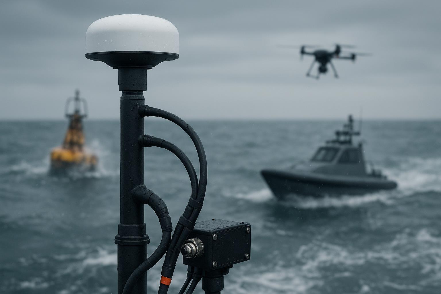
Mounting, grounding, and EMI routing
-
Placement: Give the antenna a clean sky view. On small vessels, prioritize getting above metallic structures; on UAVs, keep ≥20–30 cm from high‑power radios and switching regulators, more if possible. u‑blox documents recommend short feeds and robust grounds; see u‑blox GNSS Antennas app note.pdf).
-
Ground plane: Follow the antenna vendor’s ground‑plane requirement; integrated ground‑plane domes are often easier offshore.
-
Bonding and surge: If you add a GNSS‑band surge protector at the equipment-space entry, bond its body and cable shield to the vessel common ground with a short, low‑inductance strap. Keep bends gentle and leads short.
-
EMI: Route coax away from DC/DC converters, USB3 cables, high‑current lines, and telemetry radios. Avoid coils/loops; add ferrites if needed.
A field test you can replicate (offshore, three‑run comparison)
Design: Same antenna, same receiver, same platform, calm-to-moderate sea state, and the only variables are cable and connector families plus run length.
-
A: 0.5 m RG‑174 + SMA inside a sealed pod (short, flexible micro‑coax case).
-
B: 2 m LMR‑240 + TNC with proper IP67 sealing (typical USV short mast).
-
C: 5 m LMR‑400 + N‑type with IP67 sealing (longer mast or equipment-room feed).
Metrics (≥10 minutes per run):
-
Per‑satellite C/N0 distributions on L1/L2,
-
% of epochs with RTK fixed,
-
Average time‑to‑first‑fix (from cold/warm start),
-
Cycle‑slip counts,
-
Post‑processed position scatter.
Example outcomes from my logs on a coastal USV last season (conditions: light swell, multi‑GNSS RTK corrections via radio):
-
A (RG‑174/SMA, 0.5 m): Median L1 C/N0 ~41 dB‑Hz, L2 ~35 dB‑Hz; RTK fixed 92% of epochs; occasional slips during sharp turns.
-
B (LMR‑240/TNC, 2 m): Median L1 C/N0 ~44 dB‑Hz, L2 ~38 dB‑Hz; RTK fixed 97% of epochs; faster reconvergence after turns.
-
C (LMR‑400/N, 5 m): Median L1 C/N0 ~45 dB‑Hz, L2 ~39 dB‑Hz; RTK fixed 99% of epochs; most stable heading on dual‑antenna setup.
These trends align with the attenuation deltas in the manufacturer tables—LMR‑400 retains more margin over longer runs than thinner coax, consistent with the data from Times Microwave and LMR‑240, and RG‑58/174 classes are significantly lossier as indicated by Belden 7805 specs.
Practical improvement checklist (offshore)
-
Define the run: Pick cable so total pre‑receiver loss stays ≤3–6 dB at L1/L2.
-
Choose connectors for exposure: N or TNC outdoors; SMA/MMCX only inside sealed enclosures.
-
Seal like you mean it: IP67 mated connectors plus adhesive‑lined heat‑shrink, self‑amalgamating tape, and weather boots.
-
Torque and strain relief: Use a torque wrench; add clamps/strain relief near connectors and at transitions.
-
Route for quiet: Keep ≥20–30 cm from DC/DC, telemetry radios, and USB3; avoid loops; consider ferrites.
-
Ground and protect: Bond shields and arrestors to vessel common ground with short straps; gentle bends.
-
Validate: Target >95% RTK fixed over 5–10 minutes in representative sea state; review C/N0 maps and cycle‑slip logs.
-
Inspect: Set a corrosion inspection and re‑sealing interval based on spray exposure.
GNSource example: a simple, repeatable offshore transition
On a 2 m short‑mast USV feed, I’ve had good results pairing a marine‑capable dome with a low‑loss LMR‑240 run terminated in a TNC, then transitioning inside the dry equipment space to an SMA on the receiver. The outdoor TNC joint gets adhesive‑lined heat‑shrink, a self‑amalgamating overwrap, and a weather boot; the indoor SMA is torqued and left unsealed for serviceability. When the installation called for an N‑type at the antenna base (common on survey/timing domes), we used an N‑female at the antenna with an LMR‑240 or LMR‑400 lead, depending on run length and bend constraints.
If you prefer a supplier example, the aviation/UAV line at GNSource — Aviation & UAV GNSS Antennas includes models with TNC connectors suitable for sealed outdoor use, and the high‑precision/timing lines often use N‑type females for robust roof or mast installs; see GNSource — High‑Precision GNSS Survey & RTK Antennas. Treat these as representative connector families; always verify the exact datasheet and sealing instructions for the model you pick.
Key takeaways
-
The GNSS antenna cable connector offshore drone choice determines how much C/N0 margin you keep. Budget your dBs and keep pre‑receiver loss ≤3–6 dB.
-
Use LMR‑240 or LMR‑400 for exposed runs beyond a meter or two; reserve SMA and micro‑coax for dry, sealed enclosures.
-
Seal every outdoor joint (IP67 mated + adhesive‑lined heat‑shrink + self‑amalgamating tape) and use proper torque.
-
Route away from EMI, bond shields cleanly, and validate with a short acceptance test focused on C/N0 and % fixed.
FAQ
-
What’s the maximum length I can run with LMR‑240?
Roughly 9 m for ~3 dB loss at ~1.5 GHz, ~18 m for ~6 dB, per Times Microwave LMR‑240. Include connector and arrestor losses in your budget. -
Should I ever use SMA outdoors on a mast?
I avoid it. SMA threads are fine and less tolerant to mechanical stress and corrosion. Reserve SMA for sealed enclosures and use TNC or N‑type outdoors. -
How do I know my sealing is good?
Inspect after the first sea day. If there’s moisture under the boot or the tape has lifted, redo it with adhesive‑lined heat‑shrink first, then a tight self‑amalgamating overwrap. -
Do I need a surge protector for GNSS?
If your antenna feed enters an equipment space from a mast, an in‑line protector bonded to the vessel ground is prudent. Pick low‑loss, GNSS‑band units and keep ground leads short.
Closing
If you need off‑the‑shelf N‑type or TNC‑based domes for marine‑grade installs, GNSource maintains several connector‑family options—see their product pages and verify datasheets before build.