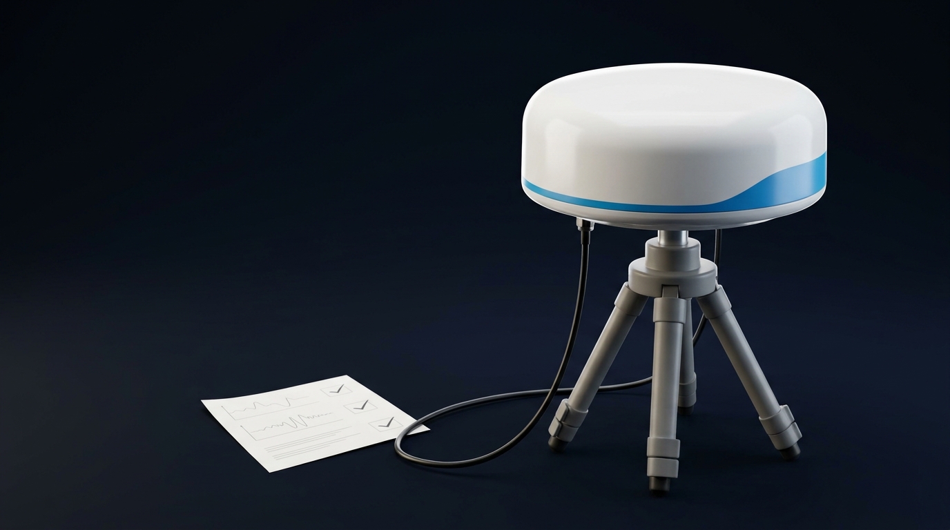
If you’ve ever watched a solid RTK lock fall apart mid‑mission for no obvious reason, you know the feeling: logs full of cycle slips, a receiver bouncing between float and fix, and a pilot asking why the same route worked yesterday. On one 3–5 kg mapping UAV we supported, the culprit wasn’t the antenna or the sky—it was the connector chain: a hand‑tight SMA at the mast bulkhead, a long run of RG‑174, and a stressed micro‑coax tail inside the fuselage. After a torque wrench, a shorter RG‑316 pigtail, and proper strain relief, CN0 ticked up across bands and re‑fix events dropped. Small mechanics, big consequences. The connector chain is only one link; choosing the antenna it feeds starts with our guide to choosing a high-precision GNSS antenna.
The GNSS antenna RF connector fundamentals that actually affect RTK
GNSS links are weak by nature. Your antenna, pigtail, connectors, and receiver form a single 50 Ω system. When any piece drifts from that target, you pay in return loss, extra insertion loss, and phase instability that shows up as worse tracking.
-
Impedance and return loss: 50 Ω continuity minimizes reflections. Reflections raise VSWR and reduce the effective signal power into the LNA. In plain terms: a bad mate or poorly matched assembly robs your link budget.
-
Insertion loss at L1/L2/L5: Coax and connectors aren’t free. Every dB lost between the antenna and the receiver is a dB you don’t have in C/N0 at the front end. As a rule of thumb, 1–2 dB additional path loss often shows up as approximately 1–2 dB‑Hz lower CN0 per satellite at the input—enough to nudge an RTK engine into more frequent re‑fixes under vibration or partial blockage. This is standard RF link budgeting; keep it conservative.
-
Mechanics and repeatability: Threaded interfaces like SMA and TNC are designed for consistency when assembled to spec. Hand‑tight “good enough” is rarely repeatable. Torque wrenches matter.
-
Vibration and mating cycles: Threaded connectors tolerate vibration better. Snap‑on micro connectors (I‑PEX/U.FL/MHF class) are intended for protected internal use and very limited mating cycles.
For primary specs and definitions, see the manufacturer pages: Amphenol RF’s overviews for SMA connectors and TNC connectors, and I‑PEX/Hirose for micro interconnects: I‑PEX MHF series and Hirose U.FL.
How connector and cable choices show up in your flight logs
If you want a quick litmus test, look at your CN0 distribution and fix convergence after a connector change. Here’s how choices propagate into data:
-
CN0 margin drops when you add coax loss or high‑VSWR interfaces. Fewer satellites cross your RTK quality thresholds simultaneously; you’ll see longer time‑to‑fix and more fix→float transitions during aggressive maneuvers.
-
Phase stability suffers when the connector isn’t fully seated or is carrying side‑loads. Vibration can modulate contact pressure microscopically, which shows up as noisier carrier residuals and more cycle slips.
-
EMI coupling increases when you route thin micro‑coax near ESCs or motor phases. Weak GNSS signals don’t forgive sloppy routing.
For a concise integration primer oriented to navigation sensors (and applicable to GNSS feeds), the VectorNav RF hardware primer is a helpful reference point.
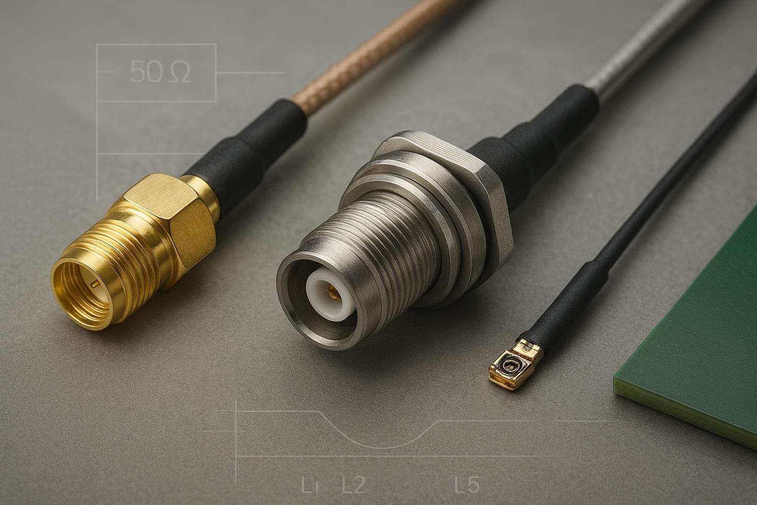
SMA, TNC, and I‑PEX/U.FL in practice on UAVs
SMA — the compact external default for most UAV builds
What matters day‑to‑day:
-
Electrical: 50 Ω; broad frequency capability in series context (into tens of GHz when specified by the manufacturer). Amphenol RF documents the family and typical characteristics here: SMA connector overview. Many SMA jacks are specified to DC–26.5 GHz; precision variants extend higher when paired correctly.
-
Mechanics: Threaded coupling. Typical torque guidance: brass SMA plugs around 3–5 in‑lb (0.3–0.6 N·m); stainless 7–10 in‑lb (0.8–1.1 N·m). Durability is commonly rated at 500 mating cycles on manufacturer datasheets. See Amphenol’s portfolio notes and datasheets for specifics, e.g., the Anti‑Torque SMA series datasheet.
-
Where it shines: External bulkheads and short pigtails on UAV masts or enclosures when size and weight matter but you still need a repeatable, torqueable interface.
-
Cable pairing: For 10–30 cm runs, prefer RG‑316 when temperature and attenuation margins matter; use RG‑174 only when strictly needed for flexibility and validate the loss budget. Times Microwave lists RG‑316 at roughly 14.5 dB/100 ft at ~1.5 GHz in its M17/RG cable datasheet. Keep runs as short as packaging allows.
-
Assembly tips: Use a panel‑mount SMA bulkhead with an O‑ring and add strain relief (heat‑shrink boot or overmold). Route the pigtail so the connector never carries cable side‑load.
TNC — choose it when mechanical abuse and service access dominate
What matters day‑to‑day:
-
Electrical: 50 Ω; commonly rated DC–11 GHz with variants extending to ~18 GHz. Typical VSWR around 1.3 across the rated band on standard models. See Amphenol RF’s family pages: RP‑TNC connectors (mechanical/electrical envelope reference) and the RF connectors overview.
-
Mechanics: Threaded coupling with a larger body than SMA, more forgiving under side‑loads. Typical mating torque guidance is ~4–6 in‑lb (0.51–0.67 N·m). Many series specify 500 minimum mating cycles.
-
Where it shines: Airframes that see frequent antenna swaps, ground handling, or cable abuse. If you need the most robust external interface and can spare a bit of weight and diameter, TNC is a solid choice.
-
Cable pairing: Same guidance as SMA, but the larger body makes strain relief and sealing simpler. IP‑rated bulkheads and protective boots are readily available. Validate VSWR after assembly.
I‑PEX/MHF/U.FL — internal‑only micro interconnects
What matters day‑to‑day:
-
Electrical: 50 Ω snap‑on micro connectors used for internal board‑to‑antenna routing. Frequency capability depends on series: I‑PEX lists MHF I and MHF 4 at up to ~9 GHz, MHF 4L and MHF 5 up to ~12 GHz, and MHF 7S up to ~15 GHz. See the I‑PEX MHF series overview and specific pages: MHF I, MHF 4, MHF 4L, MHF 5, MHF 7S. Hirose’s U.FL series covers a broad set of GHz‑class use cases as well.
-
Mechanics: Low‑profile snap‑fit designed for minimal mating cycles. Baseline Hirose U.FL is commonly documented around 30 mating cycles; higher‑cycle variants exist, but the baseline guidance is “don’t service‑mate repeatedly.” For vibration, I‑PEX offers locking variants such as MHF I LK and MHF 4L LK with higher retention.
-
Where it shines: Protected internal connections between a GNSS module and an internal patch antenna or a short micro‑coax jumper to a bulkhead. Don’t expose these to the environment. Keep micro‑coax lengths short (often 5–15 cm) and well‑strain‑relieved.
-
Cable pairing: 1.13 mm or 1.37 mm micro‑coax. Molex lists attenuation around ~2.0–2.5 dB/m for 1.37 mm and ~4.0–4.5 dB/m for 1.13 mm at ~1.5 GHz by interpolation; see the Molex micro‑coax attenuation table.
The most common integration mistakes (and what to do instead)
-
Hand‑tightening SMA/TNC and calling it done. Use a calibrated torque wrench. Brass SMA plugs are typically tightened around 3–5 in‑lb; stainless variants 7–10 in‑lb; TNC around 4–6 in‑lb. Confirm your specific part datasheet.
-
Treating micro connectors like field‑service interfaces. U.FL/MHF parts are not meant for repeated mate/de‑mate cycles or external exposure. If you must convert to an external connector, terminate to an SMA/TNC bulkhead inside a sealed enclosure.
-
Over‑long, thin coax runs. Extra length on RG‑174 or 1.13 mm micro‑coax costs precious CN0. Keep them short and consider RG‑316 for pigtails that see temperature or require lower loss.
-
Letting connectors carry cable side‑loads. Always add strain relief and clamps; the connector body should not be a lever arm.
-
Skipping VNA checks. Validate each assembled pigtail for S11/S21 before it goes into a flight article. A 5‑minute measurement can save a field failure.
-
Poor routing near noise sources. Keep GNSS coax away from ESCs, high‑current motor leads, and switching regulators; cross at right angles and add shielding where practical.
Practical improvement checklist for production and field service
-
Maintain a 50 Ω chain end‑to‑end; verify return loss on the final assembly.
-
Choose the right interface:
-
TNC when robustness and frequent servicing outweigh size.
-
SMA as the compact, torqueable default for external UAV bulkheads.
-
I‑PEX/U.FL/MHF only for protected internal links; consider locking variants for vibration.
-
-
Keep coax short and appropriate:
-
Prefer RG‑316 over RG‑174 for short external pigtails when you need better thermal stability and lower loss.
-
Keep 1.13/1.37 mm micro‑coax very short and well‑anchored.
-
-
Apply correct torque with a calibrated wrench; never rely on “feel.”
-
Add strain relief so connectors don’t carry bending moments; boot or overmold bulkheads and use panel gaskets to meet your IP target.
-
Validate every pigtail: VNA S11/S21, visual inspection, continuity pin check, and a gentle pull‑test.
-
Flight‑test what you build: log CN0 and fix state in static, hover, and dynamic profiles; compare A/B assemblies on the same airframe.
A realistic test comparison: three builds, one UAV
Platform and setup: 3–5 kg mapping UAV with a multiband GNSS antenna on a composite mast. We compared three connector/cable chains to the same receiver:
-
A) SMA bulkhead + 20 cm RG‑174.
-
B) SMA bulkhead + 20 cm RG‑316.
-
C) Internal MHF4 from module + 12 cm 1.37 mm micro‑coax to an internal patch (no external bulkhead).
Method snapshot:
-
Measured each pigtail assembly on a VNA for S11/S21 at L1/L2/L5.
-
Logged CN0 per satellite and RTK fix status in static, hover, and dynamic flight with the same route and environment on a calm day.
-
Induced rotor‑borne vibration by aggressive climbs and descents to expose any contact sensitivity.
Scenario‑specific observations (not universal guarantees):
-
The RG‑316 build (B) consistently showed ~1 dB‑Hz higher median CN0 vs the RG‑174 build (A) at L1/L2 on warm days, aligning with its lower loss spec near 1.5 GHz as listed by Times Microwave’s M17/RG cables datasheet.
-
Torque‑controlled SMA mates reduced intermittent cycle slips seen in the hand‑tight baselines. Once torqued to spec, re‑fix events during vibration maneuvers dropped noticeably in the logs.
-
The internal micro‑coax build © performed well in static tests but was more sensitive to routing near power distribution; moving the run away from ESC leads recovered ~0.5–1 dB‑Hz of CN0 on a subset of satellites. Short, well‑routed micro‑coax is viable, but it’s unforgiving of EMI.
Interpretation for RTK reliability: A seemingly small 1 dB‑Hz CN0 gain across a majority of tracked satellites often shifts the fix/float balance during marginal moments—tight turns, brief masking, or turbulence. You’ll see shorter convergence tails and fewer “mystery” re‑fixes. Think of it this way: you’re buying margin with mechanics and millimeters of coax.
FAQ — quick answers for busy integrators
-
When should I pick TNC over SMA on a drone?
- When the connector will see handling abuse, frequent servicing, or side‑loads—and you can afford the extra size/weight. TNC’s larger threaded body and available IP bulkheads make it the more rugged choice.
-
Is it OK to run U.FL/MHF directly to an external antenna?
- No. Treat these as internal connectors only. Terminate to an SMA/TNC bulkhead inside a sealed enclosure if you need an external interface.
-
How short is “short” for micro‑coax?
- As short as packaging allows—often 5–15 cm. Use 1.37 mm over 1.13 mm when bending and attenuation budgets allow, and anchor both ends to prevent motion.
-
Do I really need a torque wrench for SMA/TNC?
- Yes, if you want repeatable RF performance and fewer intermittent issues. Follow the part‑specific datasheet, but expect ranges like 3–5 in‑lb for brass SMA, 7–10 in‑lb for stainless SMA, and 4–6 in‑lb for TNC as typical guidance from Amphenol RF family data.
-
Will 1–2 dB of extra cable loss actually affect RTK?
- Often, yes. GNSS is a game of margins. Extra path loss generally reduces CN0 by a similar amount at the receiver input, which can lengthen time‑to‑fix and increase fix→float transitions under stress. Keep the path short and low‑loss.
-
How do I verify my connector chain before flight?
- Measure S11/S21 on a VNA for the exact assembly, inspect and pull‑test, then run a short log to compare CN0 and fix behavior against your known‑good build.
Next steps
If you’re standardizing on rugged, external multiband antennas that pair cleanly with SMA or TNC bulkheads for UAV builds, see GNSource for an overview of aviation/UAV GNSS antenna options. Then lock in your connector strategy, torque tools, and VNA checks so your RF chain stops being the hidden variable.
References and further reading
-
Amphenol RF — SMA Connectors (family characteristics including torque ranges and durability)
-
Amphenol RF — RP‑TNC Connectors and RF connectors overview (frequency, VSWR context for TNC family)
-
I‑PEX — MHF series overview; models: MHF I, MHF 4, MHF 4L, MHF 5, MHF 7S
-
Hirose — U.FL series (baseline mating cycles and handling)
-
Times Microwave — M17/RG Cables Datasheet (RG‑316 attenuation at ~1.5 GHz)
-
Molex — Micro‑coax attenuation (1.13 mm and 1.37 mm attenuation references)
-
VectorNav — RF hardware primer (integration practices and EMI awareness)
-
Taoglas — External Antenna FAQs (sealing, mounting, and strain‑relief considerations)