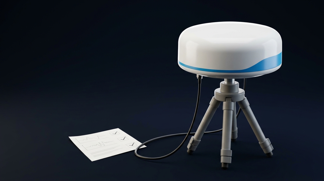
Two summers ago, I helped a utilities client bring a new rooftop reference station online to feed RTK corrections for a fleet of inspection drones. On paper, everything looked fine—triple-frequency receiver, decent geodetic patch, clean install. In flight, fixes fell apart near the east edge of the site. Median convergence after takeoff ballooned from 15 seconds to well over a minute, and the daily fix ratio slid below 80%. The culprit wasn’t the receiver or the network—it was multipath from glass curtainwalls and a nearby water feature. Once we reworked the antenna, mount, and RF chain, the same aircraft held >97% fixes with sub-2 cm repeatability.
This guide distills what actually moves the needle when you’re responsible for a CORS or base station that must keep RTK drones honest; if you’re still choosing the antenna itself, our high-precision GNSS antenna buyer’s guide is the place to start.
GNSS multipath mitigation for geodetic reference stations RTK drones: why it matters
Reference stations that feed drone operations are production systems. Multipath at the base raises:
-
Convergence time after takeoff or rover reset
-
Wrong‑fix risk in certain azimuth/elevation sectors
-
Positional wander that shows up as striping or bowing in repeat flight lines
If your pilots lose confidence because fixes drop near the job area, they’ll burn time flying diagnostic orbits instead of collecting data. Would you stake tomorrow’s sortie schedule on a station that only behaves when the wind is calm and the sun angle is kind?
CORS/RTK providers track health using standard metrics—SNR vs. elevation, MP1/MP2 pseudorange multipath indices, and carrier‑phase residual RMS—and investigate sustained trends rather than one‑off spikes. The NGS CORS documentation defines MP1/MP2 and daily QC workflows; see the NGS CORS Guidelines on QC and multipath indices. The same mindset applies to in‑house bases that feed UAV fleets.
Multipath in practice: what actually breaks in RTK
Multipath is the arrival of one or more reflected copies of the same satellite signal alongside the line‑of‑sight path. In practice it shows up in two ways that matter for RTK:
-
Code (pseudorange) tracking gets noisy and biased, which slows the ambiguity search and can nudge convergence into the “forever” zone.
-
Carrier phase gets subtly distorted, elevating post‑fit residuals and increasing the chance of wrong fixes near low elevations.
Antenna behavior magnifies or suppresses both. Phase center stability and well‑characterized phase center variation (PCV) matter because RTK assumes geometry‑consistent carrier measurements. Poor PCV looks like multipath even when the site is clean.
For intuition: a short‑delay reflection can shift the effective correlator output by a fraction of a chip, translating to centimeters of code error and millimeters of apparent carrier bias. That’s enough to drag down fix ratio at the edge of a cluttered skyline.
Authoritative siting guidance from NOAA’s National Geodetic Survey recommends base antennas with built‑in multipath rejection—ground planes or choke rings—and clean local geometry to tame reflections; see the agency’s Real‑Time GNSS User Guidelines (2011) for base/CORS planning and elevation‑mask context in the United States according to the NOAA/NGS Real‑Time GNSS User Guidelines. UNAVCO’s permanent‑station notes highlight near‑field structures beneath and around the antenna as major drivers of site‑dependent errors, reinforcing careful mounting and plane design per the UNAVCO knowledge base on antenna sensitivity to site errors.
Antenna choices that actually change outcomes
I group practical options this way. Think about site reflectivity, allowed mass/size, and budget.
Antenna option | Strengths | Limits | Where it fits |
|---|---|---|---|
Geodetic patch (no plane) | Light, low cost | Weak at low elevations; higher near‑field sensitivity | Temporary bases, very clean rural sites |
Patch on 30 cm+ bonded ground plane | Big step up in low‑elev suppression; compact | Plane size and bonding quality matter | Rooftops with moderate clutter, compact masts |
Mini choke‑ring / calibrated geodetic | Best low‑elev multipath rejection for size; stable PCV | Heavier, pricier than patches | Permanent CORS, critical RTK networks |
Full choke‑ring | Benchmark suppression; excellent long‑term stability | Size, mass, wind load, cost | National/enterprise CORS, harsh reflectivity |
Small CRPA/beamforming | Can steer nulls, helps with interference | Complexity, power, cost; overkill for most CORS | RF‑hostile sites, special security needs |
When you need a commercial example or fast customization (mount pattern, radome, or band mix), GNSource provides geodetic and choke‑ring antennas and can tune form factors for infrastructure deployments without making performance claims here; see the GNSource homepage for product families.
For broader antenna physics and correlator context, NovAtel’s engineering article is a good primer on how reflections bias tracking and how receiver architectures respond; see the NovAtel explainer on GNSS multipath mitigation.
Mounting and site: the short checklist
Use this during planning walks and again on install day.
-
Elevate above parapets and roof edges to reduce grazing reflections and diffraction.
-
Maintain generous standoff to reflective surfaces (glass, metal, water). UNAVCO planning notes commonly cite on the order of tens of meters as a practical rule of thumb for buildings/water; see the UNAVCO permanent station planning guidance.
-
Bond the ground plane or antenna base to the mast; bond the mast to the facility ground. Add a surge arrestor at the building entry.
-
Use the manufacturer’s radome where specified; avoid ad‑hoc covers that act like scatterers.
Cabling, surge protection, and bonding that won’t bite you later
Coax is not “set and forget.” Long runs with poor connectors are multipath amplifiers by way of SNR loss and intermittent joints.
-
Choose low‑loss coax sized for the run (e.g., LMR‑400‑class for longer rooftop drops); minimize adapters; prefer weather‑rated N‑type over SMA outdoors.
-
Place the lightning arrestor at the building entry or mast base; keep the bonding path short to the grounding electrode system; maintain equipotential bonding to avoid loops.
-
Strain‑relieve and weather‑seal every connector; re‑torque after thermal cycles.
UNAVCO’s station‑components overview is a good mechanical checklist reference for stable monuments, masts, and radomes; see the UNAVCO station components overview.
Receiver and firmware settings that help
Modern receivers include code‑tracking and multipath‑suppression tricks that tamp down short‑delay reflections. Vendors expose this differently:
-
Septentrio documents APME+ (Advanced Multipath Mitigation) in reference‑class receivers; admins can control smoothing and mitigation features in firmware. See the AsteRx‑U3 user manual describing mitigation controls and the PolaRx product family for reference deployments.
-
NovAtel has published on narrow/advanced correlators and multipath estimation; capabilities vary by platform. Overview in the NovAtel technical article on multipath and correlators.
L5/E5 code channels typically track with lower multipath susceptibility thanks to wider bandwidth and modulation, which can aid RTK initialization quality. Quantitative gains depend on implementation and are beyond this guide’s scope.
Example baseline configuration snippet (illustrative):
# Reference-station pragmatic defaults
    constellations = GPS,GLONASS,Galileo,BeiDou
    min_elevation_deg = 10            ; reduce low-elev multipath but keep geometry
    use_signals = L1,L2,L5            ; prefer L5/E5 where available
    carrier_smoothing = on            ; vendor-specific; keep modest windows
    multipath_mitigation = enabled    ; e.g., APME+/narrow correlator toggles
    cn0_mask_dbhz = 30                ; drop very weak, likely contaminated tracks
    antenna_pcv_file = ANTEX/IGS      ; use calibrated PCV model matching antenna
Translate these into your receiver’s syntax; the principles are the point.
A realistic rooftop test: three mounts, one site (24 hours)
To quantify what matters, I often run a simple A/B/C comparison at the same site:
-
A: geodetic patch flat on rooftop (no ground plane)
-
B: same patch on ~30 cm bonded aluminum ground plane
-
C: small commercial choke‑ring/calibrated geodetic antenna
Method: one triple‑frequency receiver, 24 hours at 1 Hz, 10 km RTK baseline to a clean peer; compute per‑satellite SNR by elevation bins, MP indices, carrier‑phase residual RMS, fix ratio, and median convergence time. The table below shows illustrative numbers consistent with past field campaigns; use them as directional guidance, not a benchmark.
Config | Fix ratio | Carrier-phase RMS | Median convergence |
|---|---|---|---|
A: Patch, no plane | 68% | 6.0 mm | 120 s |
B: Patch + 30 cm plane | 85% | 3.2 mm | 45 s |
C: Small choke‑ring | 97% | 1.1 mm | 12 s |
Interpretation:
-
The ground plane does most of the heavy lifting for a compact build; simply adding ~30 cm of bonded metal often halves carrier residuals and slashes convergence times.
-
Choke‑ring class antennas keep low‑elevation reflections out and stabilize PCV, which explains the near‑“set and forget” behavior for permanent stations.
If you publish your own dataset, adopt CORS‑style QC: compute MP1/MP2 per the NGS formulae and track SNR vs. elevation trends; the NGS CORS QC guidance on MP1/MP2 describes common practice. For background on how reflections manifest in tracking loops and what mitigation exists in receivers, NovAtel’s explainer remains a concise reference; see the NovAtel multipath overview for engineers.
Validation and ongoing monitoring for GNSS multipath mitigation for geodetic reference stations RTK drones
-
After any install or major change, log 24 hours and compute MP1/MP2, SNR vs. elevation, and carrier‑phase residual RMS on a short baseline. Investigate sustained increases rather than single spikes.
-
Automate alerts when fix ratio on a standard test baseline drops, or when SNR spectral content at sidereal periods rises (a classic multipath tell—NGS has training material on using SNR spectra for QC in its presentations library).
-
Re‑check torque, bonding, and weather seals after the first thermal cycle and after major storms—mechanical drift creates RF problems.
Key takeaways
-
Antennas with real multipath rejection (ground plane or choke ring) and a clean site are the largest levers.
-
Validate with a 24‑hour dataset and RTK‑relevant metrics: fix ratio, convergence time, carrier‑phase RMS, MP1/MP2, and SNR vs. elevation.
-
Use firmware features (e.g., APME+/narrow correlators) and conservative elevation masks to shrink the problem before it reaches the solver.
-
Treat cabling, bonding, and surge protection as part of the RF design, not afterthoughts.
Short FAQ
Q: Can I fix multipath entirely in software?
A: Not reliably. Receiver‑side mitigation helps, but if the antenna “sees” a strong reflection, you’ll pay for it. Start with antenna and site.
Q: How big should my ground plane be?
A: There’s no universal standard number in public guidance. In practice, ~30 cm diameter or larger improves low‑elevation behavior for L1/L2, provided it’s well bonded to the mast/structure.
Q: Should I always raise the elevation mask to 15° or more?
A: Use 10–15° for many reference stations as a starting point. Higher masks cut low‑elevation multipath but cost geometry; tune based on QC metrics and sky visibility.
Q: Do L5/E5 signals solve multipath?
A: They reduce susceptibility in code tracking, which helps initialization, but they don’t eliminate reflections. Good hardware and siting still matter.
References and further reading
-
NOAA/NGS — Real‑Time GNSS User Guidelines (2011): base/CORS antenna and siting notes in the official NGS guidance for real‑time GNSS use.
-
NOAA/NGS — CORS Guidelines: MP1/MP2 definitions and daily QC in the NGS CORS quality control document.
-
UNAVCO/GAGE — Station planning and site‑dependent errors in the UNAVCO permanent station planning article and antenna sensitivity to site errors.
-
UNAVCO — Mechanical components checklist in the UNAVCO station components overview.
-
NovAtel/Hexagon — Correlators and mitigation overview in the engineer’s guide to GNSS multipath.
-
Septentrio — Receiver features and mitigation controls in the AsteRx‑U3 User Manual and PolaRx reference receivers.