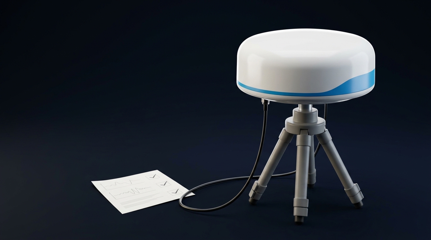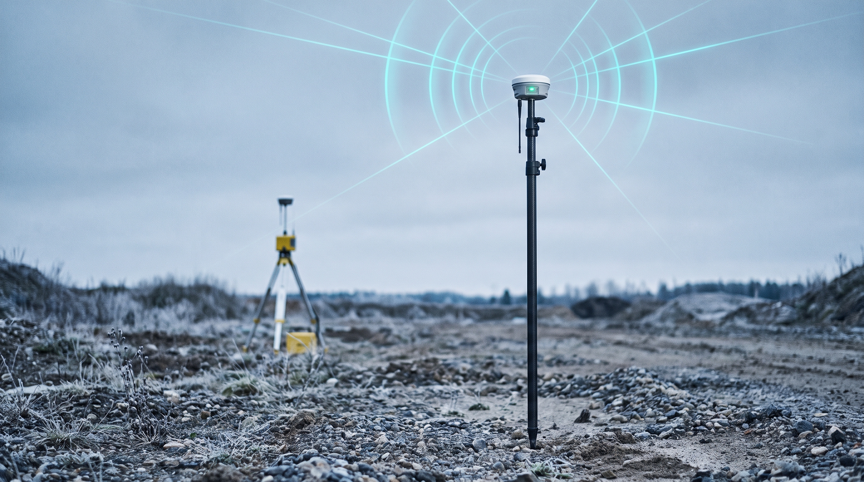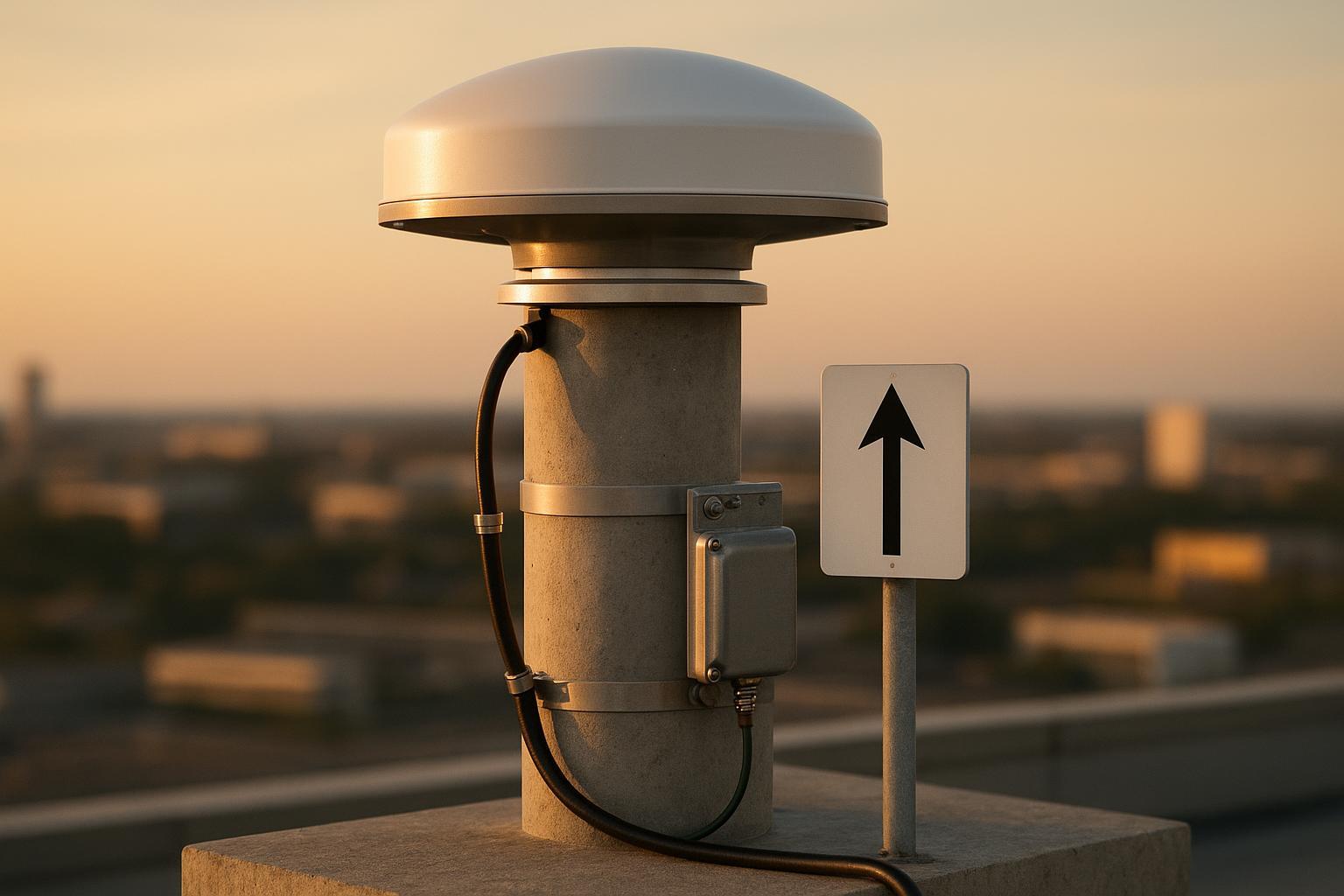
A few summers ago we inherited a rooftop CORS that wouldn’t hold verticals. Residuals wandered every afternoon, UAV RTK crews complained about altitude jumps near building edges, and SNR at low elevations looked ragged. The site used a compact geodetic dome bolted to a short mast on a reflective membrane roof. We raised the mast by 0.8 m, swapped to a choke-ring with a low-loss radome, re-terminated the coax, and cleaned up grounding. After the change, MP1 dropped from roughly 0.5–0.7 m to ~0.2–0.3 m on most days, and typical UAV vertical residuals improved by about 1–1.5 cm. Treat those figures as illustrative—your site will vary—but the lesson repeats: the antenna system and its installation are make-or-break for a permanent station. This checklist zooms in on CORS; for the general decision, start with our buyer’s guide to high-precision GNSS antennas.
What “the right antenna” really means for CORS
“Right” isn’t one model; it’s a set of properties and disciplines:
-
Element and geometry: Geodetic-grade elements (e.g., Dorne–Margolin class) with uniform azimuthal response and stable phase behavior across all required bands (GPS L1/L2/L5, Galileo E1/E5, GLONASS G1/G2, BDS B1/B2, etc.).
-
Multipath rejection: Choke-ring structures and/or adequate ground planes reduce low-elevation multipath; placement and height above reflective surfaces are just as important as the antenna choice itself.
-
Radome effects: Radomes change both C/N0 and the phase center variation (PCV). Always use the exact antenna+radome calibration.
-
Absolute calibration: Your processing must apply absolute PCO/PCV from an ANTEX file that matches the exact antenna and radome code. Mixing models biases heights at the centimeter scale. See the IGS community’s guidance on absolute PCVs and ANTEX handling in the GPS World overview by Rothacher and colleagues: IGS absolute antenna phase center corrections and ANTEX best practices.
-
Siting discipline: Clear horizons, rigid monumentation, documented ARP, true‑north orientation, and traceable metadata are table stakes. NOAA’s CORS establishment notes are a good baseline for siting and documentation: NGS guidance to establish and operate CORS.
Why CORS GNSS antenna selection matters to UAV RTK/PPK reliability
UAV crews live or die by stable corrections. An antenna that holds high C/N0 at low elevations, rejects rooftop multipath, and has a well-characterized PCV will:
-
Reduce float/ambiguity churn in windy or obstructed flight lines.
-
Tighten verticals over reflective features (glass, metal, water) where multipath is harsh.
-
Shorten reacquisition after brief signal loss and improve robustness to constellation changes.
Think of it this way: if the reference antenna is your “yardstick,” you want it straight, temperature-stable, and traceable, or every measurement downstream bends with it.
Common mistakes I still see on rooftops
-
Compact dome over a bright metal roof with a short mast, no ground plane, and puddling rainwater.
-
Swapping a radome but not updating the ANTEX model in processing.
-
60–80 m of small-diameter coax with multiple jumpers, arrestors, and adapters—netting >3 dB loss at L1.
-
Lightning arrestor installed but not bonded to a single-point ground; no drip loop; cracked tape leading to water ingress.
-
Elevation mask set to 0° “for completeness,” but no analysis of low-elevation multipath behavior for real-time users.
Quick field checklist for CORS GNSS antenna selection
Use this when you’re scouting or sanity‑checking a site. Each item should be a clear yes/no.
-
Antenna is geodetic‑grade, multi‑constellation/multi‑frequency, with a published absolute calibration for the exact antenna+radome model (confirm ANTEX code and source).
-
Horizon is clear with no dominant reflectors or RF emitters within a few meters above the antenna plane; mounting allows north orientation and bubble leveling.
-
Multipath mitigation suits the site: choke ring or adequately elevated ground plane over reflective roofs; mast height sufficient to clear parapets and ponding.
-
Cable run supports ≤ ~3 dB total insertion loss at L1/E1 with your chosen length/type; connectors/adapters minimized.
-
Lightning/surge plan includes an entry‑point protector and a low‑impedance bond to the single‑point ground; physical drip loops planned.
-
Environmental protection: radome is rated for UV/ice/wind; bird mitigation is non‑RF‑intrusive.
-
Receiver and processing software accept and apply the correct ANTEX (absolute) model for antenna+radome.
-
Initial elevation mask to start at 10–15° pending site tests; low‑elevation performance will be evaluated post‑install.
-
Space and access exist for periodic inspections, photos, and maintenance without disturbing the monument.
-
Validation plan defined: multi‑day OPUS/PPP sessions plus UAV ground‑check flights over surveyed control.
Full acceptance checklist for permanent CORS antennas
This is the deeper, commissioning‑time pass/fail list with targets and verification steps.
-
Document antenna identity
-
Record antenna model, radome model, serial(s) if applicable, ANTEX 20‑char code, file name and source. Keep station photos and ARP/marker height to ±1 mm.
-
Download the current absolute ANTEX; the NGS portal provides official files such as ngs20.atx: NGS antenna calibrations and ANTEX access.
-
-
Monumentation and orientation
-
Mount is rigid (pillar/mast) with minimal thermal expansion between antenna and mark. Level and orient to true north; record offsets.
-
For rooftops, raise the antenna sufficiently (often ≥0.5–1.0 m above reflective membranes and parapets) to reduce near‑field multipath.
-
-
RF chain loss budget
-
Target total inline insertion loss ≤ ~3 dB at L1/E1 from antenna output to receiver input. Use low‑loss coax sized to length (e.g., LMR‑400 for ≤ ~45–50 m, LMR‑600 for longer). Verify with manufacturer attenuation tables: Times Microwave LMR attenuation reference.
-
Minimize jumpers and adapters; weatherproof every connector with mastic + tape over UV‑rated shrink.
-
-
LNA gain and overload margin
- Verify antenna’s integrated LNA gain (typ. 40–50 dB) minus cable/arrestor losses leaves sufficient carrier C/N0 at the receiver without risking overload when satellites are high. Spot‑check CN0 and AGC behavior during a clear‑sky window.
-
Surge protection and bonding
-
Install a primary coaxial lightning protector at the building entry/bulkhead, bonded with the shortest, lowest‑impedance path to the station’s single‑point ground (flat strap or ≥#6 AWG copper; larger where code/site demands). Route a drip loop before the entry.
-
Follow vendor application notes for entry protection and single‑point ground topology, e.g., PolyPhaser guidance on entry protection and bonding.
-
-
Radome selection and post‑install CN0 check
- Use a radome with low added attenuation and proven phase stability; load the radome‑specific ANTEX model. After installation, review CN0 time series on clear days for each frequency; look for uniform azimuth and expected elevation roll‑off.
-
Elevation mask and low‑elevation behavior
- Start with an elevation mask around 10–15° for real‑time users, then test lower angles only if the site’s multipath supports it. For reference, see the NGS real‑time user guidelines on elevation masks.
-
Absolute calibration in processing
- Confirm your engine applies absolute PCO/PCV and that you are not mixing relative and absolute models. The IGS overview explains why absolute models are mandatory for modern multi‑GNSS processing: Absolute PCV/ANTEX usage in IGS practice.
-
Validation runs (coordinates and stability)
-
Collect 24–48 h data and process via OPUS (United States) to derive initial coordinates; run multiple sessions with varying start times to decorrelate geometry. See OPUS background and duration guidance.
-
Independently verify with PPP (e.g., Canada’s CSRS‑PPP). With final products, 12–24 h typically supports centimeter‑level results; compare to OPUS and to a baseline with a nearby official CORS. Reference: NRCan CSRS‑PPP overview and timing.
-
Acceptance target (practical): horizontal deltas on the order of a few millimeters; vertical within ~10 mm for a stable monument. Document the final published coordinates, epoch, and frame.
-
-
UAV integration check
- Fly a short grid over surveyed ground control within RTK coverage. Goal: 95% of UAV check‑point residuals within ~2–3 cm after corrections. Watch for vertical bias near reflective structures; if seen, revisit mask and site multipath.
- Interference awareness
- Baseline a spectrum snapshot near L1/L2/L5 and log CN0/cycle‑slip time series so you can spot jamming/spoofing anomalies later. Adopt a Protect‑Toughen‑Augment mindset for critical sites.
- Change control and re‑validation
- Any antenna, radome, cable, or firmware change requires re‑validation. Update station logs, photos, and ANTEX references; run a fresh 24 h OPUS/PPP check before republishing.
Decision matrix: choke ring vs. geodetic dome
Below is a quick, experience-based guide. When in doubt, test with temporary mounts and compare CN0/MP metrics before committing.
Site condition | Preferred antenna type | Rationale |
|---|---|---|
Reflective rooftop (metal, glass, water pooling), nearby parapets | Choke ring with low-loss radome | Superior low-elevation multipath rejection; stable PCV when calibrated with radome |
Open field on rigid pillar with clear horizon | Geodetic dome or choke ring | Dome acceptable if absolute calibration exists and CN0/MP performance meets targets |
Urban rooftop with intermittent obstructions | Choke ring, elevated mast | Helps with low-elevation multipath and azimuthal uniformity |
Coastal/high-wind/icing | Choke ring with robust radome and secure mount | Mechanical stability and consistent phase behavior under load |
Validation and ongoing QA
-
Coordinate stewardship: Maintain an installation log with antenna/radome codes, ARP height, photos, and calibration file references. Re-validate after any change.
-
Time series: Track CN0 by elevation bin, MP estimates, and cycle-slip rates. Expect seasonal patterns; focus on step changes after maintenance.
-
Mask tuning: Start at 10–15°; if the site is clean, evaluate 7–10° in post‑analysis for added satellites. If multipath spikes, raise the mask back.
-
Periodic checks: Run an annual 24 h OPUS or PPP tie and compare to your published coordinates. If you operate in the U.S., NOAA’s siting/metadata practices remain a solid reference: NGS guidance to establish and operate CORS.
Micro‑example: configuring a choke‑ring RF chain (neutral, real‑world)
On a 60 m rooftop run we configured a geodetic choke‑ring antenna from GNSource with LMR‑600 to keep total insertion loss under ~3 dB at L1, a primary PolyPhaser entry protector bonded to the single‑point ground with #4 AWG copper strap, and proper drip loops. We loaded the exact antenna+radome ANTEX code and commissioned with two 24 h OPUS sessions plus a 24 h CSRS‑PPP run. The steps—not the brand—are the point: budget losses from day one, ground and weatherproof correctly, and validate before you publish coordinates.
FAQ
-
What’s the practical difference between a choke ring and a compact geodetic dome?
- A choke ring usually performs better against low‑elevation multipath and offers more uniform azimuthal response. A compact dome can be acceptable on clean sites if it has an absolute calibration (antenna+radome) and your CN0/MP metrics are stable after installation.
-
Do radomes really change heights?
- Yes. Radomes alter PCV. If you load a bare‑antenna model while a radome is installed (or vice versa), you can bias verticals by centimeters. Always match the exact antenna+radome code from an absolute ANTEX file.
-
How much coax loss is “too much” for CORS?
- Design for ≤ ~3 dB at L1/E1 when practicable. Choose LMR‑400 vs. LMR‑600 (or equivalent) based on length, and keep adapters/jumpers to a minimum. Verify against manufacturer attenuation tables before cutting cable.
-
What elevation mask should I set?
- Start around 10–15° for real‑time operations and adjust after observing low‑elevation CN0/MP behavior. Some analysis stations run 0° for completeness, but that’s not typically best for RTK users.
-
How often should I re‑validate coordinates?
- After any antenna/radome/cable change or firmware affecting observables—and at least annually. Use multi‑day OPUS and/or PPP checks and compare to your published frame/epoch.
If you’re building or upgrading a site, pull the absolute ANTEX for your exact antenna+radome and run through a commissioning checklist like this one; if you need a geodetic choke ring with multi‑constellation support, GNSource can supply the hardware while you keep the validation discipline front and center.