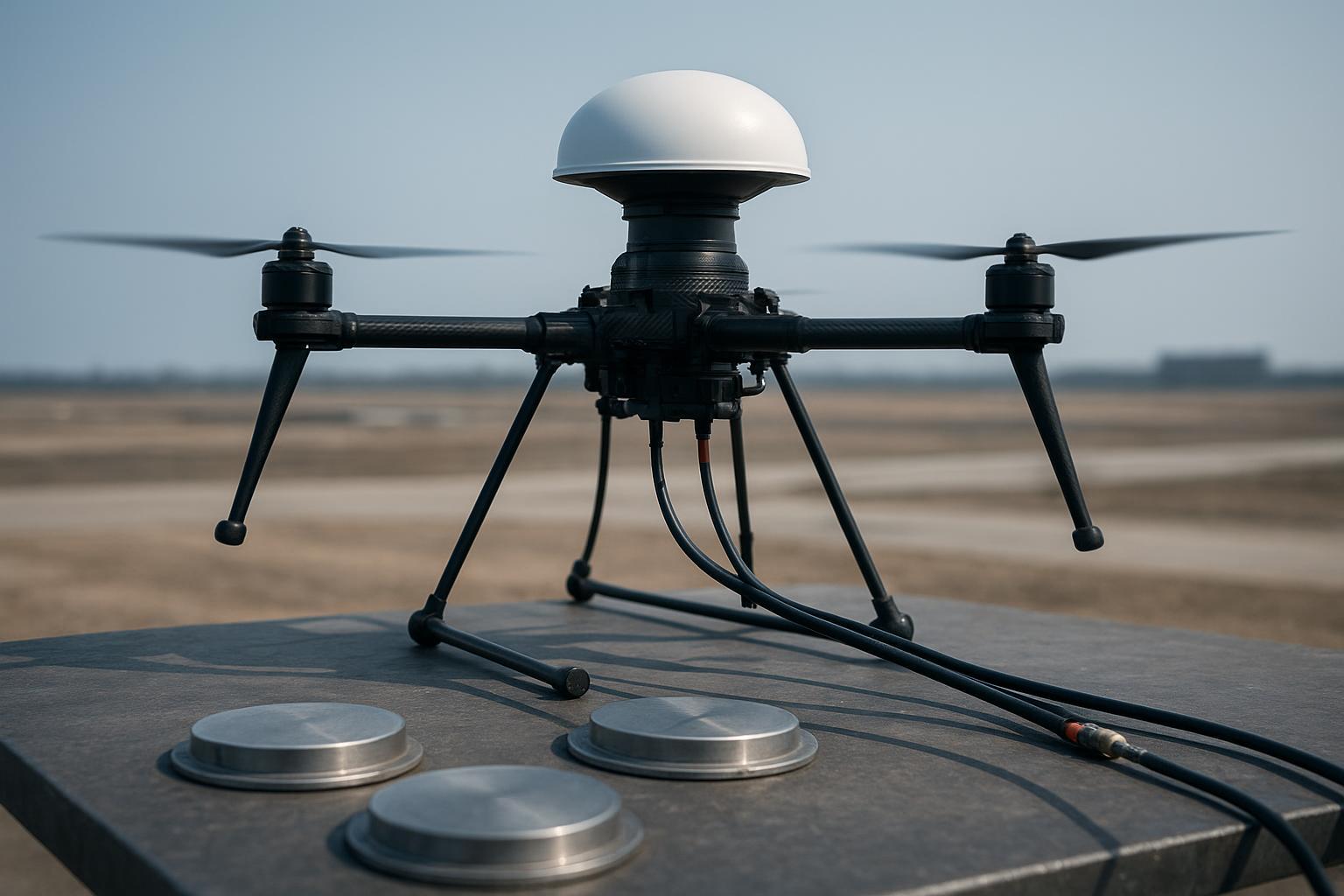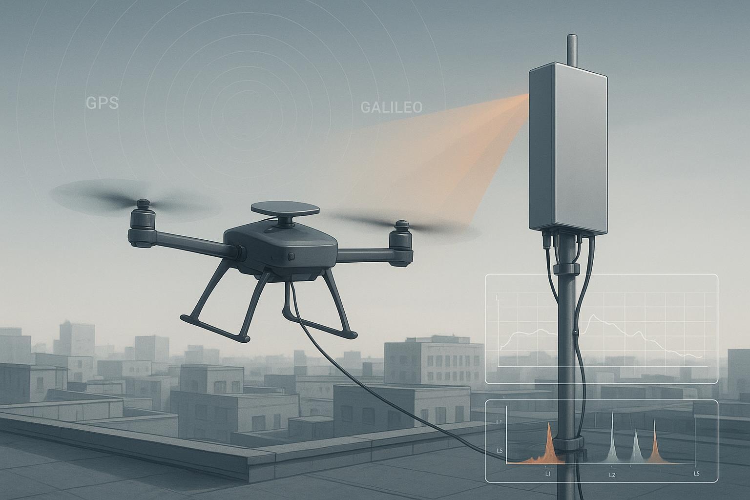
If you’ve ever watched a rock‑solid RTK link turn skittish the moment you lift off near a downtown macro site, you’re not alone. On a recent rooftop commissioning, our rover looked clean during warm‑up, then bled C/N0 by a few dB and fell into float each time the bird yawed toward a 5G sector panel across the alley. No sirens, no obvious tones—just a raised noise floor, more cycle slips, and a fix that wouldn’t stick.
Here’s the deal: most “5G problems” we encounter in cities aren’t classic on‑band jammers. They’re coexistence issues—receiver desensitization, intermodulation by strong out‑of‑band energy, and geometry‑driven multipath—that quietly erode RTK margins. This post distills what’s worked for us: how to detect the fingerprints of interference quickly, which mitigations move the needle — including the CRPA options in our anti-jamming GNSS antenna guide — and how to validate improvements so you can fly with confidence.
What 5G does to GNSS (without the myths)
When a UAV flies near a 5G macro or small cell, strong adjacent‑band or out‑of‑band energy can push parts of the GNSS front end toward compression. That triggers three practical effects:
-
Blocking/desensitization: the effective noise floor rises, so satellites appear weaker and tracking loops falter.
-
Intermodulation products: nonlinear stages generate spurs that can fold into L1/L2/L5, creating loss of lock or jittery carrier phases.
-
Multipath emphasis: urban structures and antenna side‑lobes feed more reflections, confusing code/carrier estimators.
Regulators and engineering bodies have been explicit that immunity hinges on receiver design (filtering, linearity, AGC strategy) and must be characterized across frequency and power, not by a single figure. See the National Telecommunications and Information Administration’s 2025 guidance on receiver blocking and immunity characterizations in its Receiver Interference Immunity report and best‑practices companion, which push for better front‑end robustness and AGC behavior under strong adjacent signals. For background, consult the descriptions in the NTIA’s Receiver Interference Immunity Issues and Recommendations (2025) and its Best Practices for Interference‑Resilient RF Receiving Systems (2025).
-
According to the NTIA’s Receiver Interference Immunity report (2025), improving blocking performance and measuring desensitization versus frequency is central to urban coexistence challenges: see the sections on adjacent‑band effects and immunity characterization: NTIA Receiver Interference Immunity report (PDF)
-
NTIA’s Best Practices (2025) also highlight how AGC and nonlinearity shape resilience, recommending conservative loop and gain strategies under RFI: NTIA Best Practices for interference-resilient receivers (PDF)
In short: expect variability across receivers and sites. Plan to measure, classify, and mitigate rather than assume a universal penalty.
Why urban 5G hurts RTK specifically
RTK lives or dies on clean, continuous carrier phase. When the noise floor lifts or spurs pop into band, you’ll see:
-
Longer time‑to‑fixed (especially after yaw maneuvers and turns toward the emitter)
-
Higher float ratio and frequent re‑convergence cycles
-
Increased cycle‑slip counts and ambiguity resets
-
Drifting horizontal error tails during low‑elevation satellite passages
Peer‑reviewed urban work emphasizes that multipath and obstruction alone can crater fix availability; interference stacks on top of that. For a sense of scale (different city, different setup), a 2024 study on modified RTK methods in dense Tokyo reported fix‑availability gains versus baseline approaches in difficult urban geometry—underscoring how fragile carrier‑phase continuity becomes in city canyons. See Modified RTK‑GNSS for Challenging Environments (2024) for urban RTK availability context: https://pmc.ncbi.nlm.nih.gov/articles/PMC11086102/
A fast, field‑ready detection workflow
I use two complementary toolchains: what the receiver already knows about its RF world, and what a spectrum view shows.
- Receiver telemetry and logs
-
Watch C/N0 trends and lock stability across constellations. Sudden multi‑sat dips without clouds are a flag.
-
Track AGC if exposed. Rising AGC with stable sky geometry hints at front‑end overload.
-
Note RTK state transitions, integer ambiguity flags, and cycle‑slip counters.
-
If your receiver offers interference widgets (spectrum windows, notch/WBI), baseline them in a clean area first.
For integrated tools and mitigation modes (narrowband notch, wideband interference suppression), Septentrio’s AIM+ documentation provides a clear reference model for how modern receivers expose and treat interference within the UI and logs.
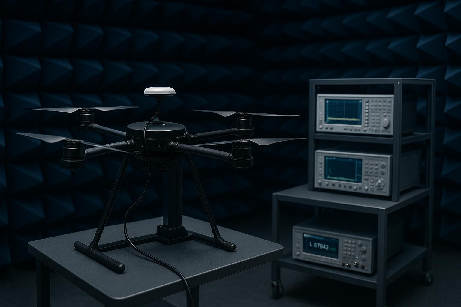
- Spectrum survey (bench or field)
-
Start with the receiver’s built‑in spectrum window across L1/L2/L5 if available.
-
For ambiguous cases, use a portable real‑time spectrum analyzer with a GNSS preselector or low‑noise front‑end to catch intermittent spikes—Rohde & Schwarz’s FSW class is a typical reference point for the required dynamic range and real‑time analysis: Rohde & Schwarz FSW signal and spectrum analyzer
-
Classify the pattern: narrow tones (try notch), broadband elevation (use wideband mitigation), intermittent pulses (time‑correlate with 5G TDD or your own telemetry links).
- Correlate events
-
Time‑sync spectrum captures with rover logs.
-
Mark headings/yaw angles: interference often spikes when the antenna side‑lobe faces the emitter.
-
Replay flights and overlay RTK state, C/N0, AGC, and interference events per minute.
Common mistakes I still see
-
Mounting the GNSS antenna low, shadowed by carbon fiber or payloads
-
Ignoring ground plane size for patches, or assuming a helical doesn’t need separation
-
Long, lossy RF cable runs with mediocre shields and multiple adapters
-
No targeted filtering; relying solely on the receiver’s built‑in rejection
-
Leaving firmware at defaults; not enabling interference monitors or logs
-
Flying acceptance missions without a repeatable RF test plan
Mitigation playbook that actually moves the needle
Antenna selection and mounting
-
Prefer RHCP antennas with low axial ratio and good out‑of‑band (OOB) rejection. If the airframe can host a proper ground plane, a multiband patch on a larger plate improves multipath rejection; when ground plane area is constrained, quality helical designs can maintain performance without a chassis ground.
-
Mount high and sky‑facing. Keep separation from your own radios (telemetry, Wi‑Fi, LTE/5G hotspots) and from ESCs/power harnesses.
-
For patches, u‑blox guidance shows benefits from larger ground planes; even 50×50 to 70×70 mm plates help on small airframes. For helicals, vendors like Tallysman document models that do not require a ground plane, which can simplify UAV integration.
Helpful references:
-
u‑blox GNSS Antennas Application Note (ground plane and placement specifics).
-
Tallysman HC885XF helical datasheet (no ground plane requirement example).
Front‑end filtering and linearity
-
Use low‑loss band‑pass filters sized to your bands (L1/L2/L5) and add a targeted notch if a specific blocker dominates. Keep total passband insertion loss low (on the order of 1–2 dB per stage—confirm from the vendor datasheet for your exact part) and ensure sufficient stopband rejection around 3.3–3.8 GHz and, if needed, 4.9–6 GHz.
-
Keep pre‑LNA losses to a minimum. Choose LNAs with enough P1dB/IP3 headroom so that nearby 5G downlink levels don’t push you into compression. NTIA’s 2025 best‑practices paper underlines how AGC and linearity set your immunity envelope.
Cabling and connectors
-
Short, well‑shielded RF runs with controlled impedance. Avoid long RG‑174 at L1/L2 unless the loss budget proves it’s acceptable; RG‑316 or semi‑rigid can buy margin. Always pull the datasheet loss in dB/m at your frequency and compute the total.
-
Minimize adapters and ensure 360° shield terminations. Add ferrites on noisy harnesses to reduce common‑mode coupling.
Receiver/firmware settings
-
Enable interference monitoring features. For narrowband tones, engage manual/auto notch; for broadband elevation, enable wideband interference mitigation (WBI) if your receiver supports it. Septentrio’s AIM+ materials provide a clear reference for how these modes work in practice.
-
Tune tracking loops conservatively under RFI. Avoid loop bandwidth expansions that chase noise. If exposed, monitor AGC and keep it from pegging high during urban fly‑bys.
Fallback logic and ops
- Define mission rules for degraded RTK: switch to PPP/DFRTK if available, widen protection levels from INS fusion, or pause the mission if fix cannot be sustained across critical segments.
Two realistic scenarios and what we measured
These examples illustrate the process and kinds of gains we’ve seen. Values are provided as realistic, illustrative numbers, not universal promises—expect differences by receiver, airframe, and site.
Scenario A — Rooftop static near a macro 5G sector
-
Setup: dual‑band L1/L2 rover on a carbon‑frame UAV, initial mount 8 cm above deck with small patch and 60 mm ground plate; 5G sector panel ~40 m away across the alley. Logged 60 minutes per condition.
-
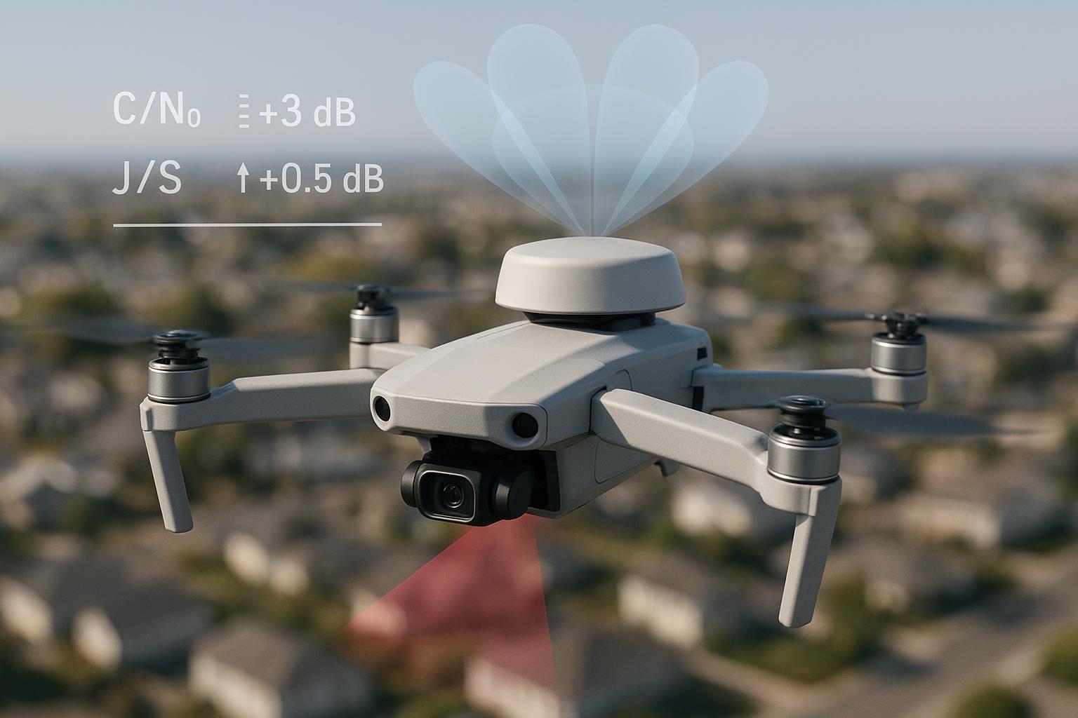
Baseline symptoms: C/N0 dips of 2–3 dB‑Hz when the airframe yawed toward the sector; intermittent float after minor yaw, increased cycle slips.
-
Mitigations applied: moved antenna to a mast +15 cm higher with a 100×100 mm ground plate; added a low‑loss L1/L2 band‑pass and a narrow notch targeting the identified blocker; shortened RF run by 25 cm with RG‑316; enabled receiver’s wideband mitigation.
Illustrative KPIs (example)
Metric | Baseline | Mitigated |
|---|---|---|
Fix rate (% of time) | 68% | 88% |
Time‑to‑fixed (median / P90) | 41 s / 95 s | 24 s / 52 s |
Float ratio (%) | 32% | 12% |
H95 horizontal error (m) | 0.42 | 0.28 |
Median C/N0 (L1, dB‑Hz) | 37.5 | 39.2 |
Cycle slips (#/hr) | 21 | 9 |
Interference events/hr (spectrum) | 14 | 6 |
Scenario B — Street‑canyon fly‑through with onboard telemetry radio
-
Setup: repeatable 600 m path between mid‑rise buildings; telemetry at 900 MHz colocated near the GNSS pod; occasional turns align the antenna side‑lobe with a small cell on a lamp post.
-
Baseline symptoms: fix drops during tight turns and near small‑cell clusters; telemetry bursts correlate with brief C/N0 dips.
-
Mitigations applied: moved GNSS antenna to a top‑hat location; added ferrites on telemetry harness; inserted a wider band‑pass and improved shielding on the RF run; enabled notch for a narrow spur seen in L2.
Illustrative KPIs (example)
Metric | Baseline | Mitigated |
|---|---|---|
Fix rate (% of path) | 61% | 81% |
Re‑fix after slip (P90) | 7.2 s | 3.6 s |
Worst‑case horiz. error (m) | 0.92 | 0.54 |
Median C/N0 (L2, dB‑Hz) | 33.1 | 35.0 |
Cable loss mini‑table (example—fill with your datasheet values)
Cable type | Length (m) | Loss at ~1.575 GHz (dB/m) | Total loss (dB) | Notes |
|---|---|---|---|---|
RG‑174 | 0.45 | 2.3 | 1.04 | Avoid long runs |
RG‑316 | 0.30 | 1.4 | 0.42 | Better shield |
0.085″ semi‑rigid | 0.25 | 0.8 | 0.20 | Best margin |
Note: Replace the dB/m figures with your vendor’s datasheets (Times Microwave, Amphenol, etc.). They vary by construction.
Micro‑example: integrating a high‑rejection UAV antenna from GNSource
On a mid‑size inspection UAV with a tight ground‑plane budget, we swapped a generic patch for a lightweight RHCP helical option with stronger out‑of‑band rejection sourced from GNSource. Mounted on a short mast above carbon structure, we routed a shorter RG‑316 feed and added a compact L1/L2 band‑pass up front. The changes cut pre‑LNA loss, improved sky view, and reduced side‑lobe pickup toward nearby small cells. In A/B flights, the mitigated build showed fewer cycle slips and faster re‑fix after turns. For similar options and form‑factor variants, see GNSource’s Aviation & UAV GNSS Antennas: https://gnssource.com/products/aviation-uav
What to log and how to validate improvements
-
Log raw observables, C/N0 per signal, ambiguity status, cycle slips, AGC, and RTK state at ≥1 Hz. Keep spectrum snapshots or real‑time captures for event correlation.
-
Compute KPIs: fix‑rate, median/P90 time‑to‑fixed, float ratio, H95 error, median C/N0 per band, and interference events per hour.
-
Make tests repeatable: same route, time of day (satellite geometry), and environmental conditions whenever possible. Yaw‑sweep on a rooftop is a fast way to expose angle‑dependent susceptibility.
-
Acceptance heuristic: look for clear directional improvements—e.g., +1–3 dB‑Hz median C/N0 on vulnerable bands, fewer slips, shorter re‑fix, and ≥10–20% absolute fix‑rate gain versus your baseline. Treat these as site‑ and receiver‑specific targets, not universal guarantees.
Key takeaways
-
Most urban “5G issues” are coexistence problems that lift the noise floor and stress tracking, not just obvious on‑band jammers.
-
RTK margins erode first: time‑to‑fixed stretches, float time grows, and cycle slips multiply—plan to measure these directly.
-
Detect fast with receiver telemetry and a quick spectrum look, then classify: narrowband, broadband, or intermittent.
-
Mitigate where it matters: better antenna placement/grounding, low‑loss cabling, targeted filtering, and sane firmware settings.
-
Validate with repeatable KPIs and keep raw logs; improvements that don’t show up in fix‑rate or re‑fix time aren’t real.
FAQ
Q: Will a single band‑pass filter fix GNSS interference near 5G sites? A: Sometimes it’s enough, but many urban cases need a combination: better placement, a larger ground plane or helical swap, short low‑loss cabling, and—when a specific blocker is present—a notch or tighter preselection.
Q: How close is “too close” to a 5G macro site for reliable RTK? A: There’s no universal distance. Susceptibility depends on your front‑end design, filtering, and angles of exposure. Do a rooftop yaw‑sweep test and measure fix‑rate, re‑fix time, and C/N0 to set your operating envelope.
Q: Can the UAV’s own radios be the bigger problem? A: Yes. Telemetry bursts, Wi‑Fi, or an onboard 4G/5G modem can raise the local noise floor or inject spurs. Separate antennas, add ferrites, and consider scheduling or power limits during critical RTK segments.
Q: Are wideband interference modes safe to leave on permanently? A: Generally yes if your receiver supports it, but verify tracking margins in clean environments—some modes trade small amounts of sensitivity for robustness.
Further reading and references
-
Septentrio’s overview of interference mechanisms and mitigation (AIM+, WBI).
-
NTIA’s 2025 Best Practices for interference‑resilient receivers
-
Rohde & Schwarz FSW analyzer for real‑time capture of intermittent interferers
-
Urban RTK availability context: Modified RTK‑GNSS for Challenging Environments (2024): https://pmc.ncbi.nlm.nih.gov/articles/PMC11086102/
Next steps: If you need a lightweight RHCP option with stronger out‑of‑band rejection or a custom form factor for a tight airframe, explore GNSource’s Aviation & UAV GNSS Antennas: https://gnssource.com/products/aviation-uav