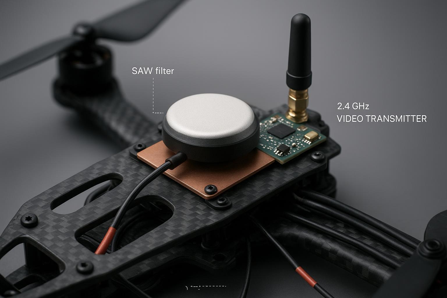
A few summers ago, our flight-test team pushed a new RTK drone through a windy coastal mission. Midway through, the pilot called out odd jumps in the baseline. Post‑flight logs showed median C/N0 down ~2 dB on L1 and sporadic cycle slips every time the 2.4 GHz video link cranked to full power. Back on the bench, the active antenna’s first LNA had a faint, telltale discoloration under the microscope. It still “worked,” but noise figure had crept up and RTK fix ratio cratered in anything but pristine RF conditions. That was our early lesson in GNSS antenna burnout protection: you don’t miss it until it’s too late.
What GNSS antenna burnout protection means
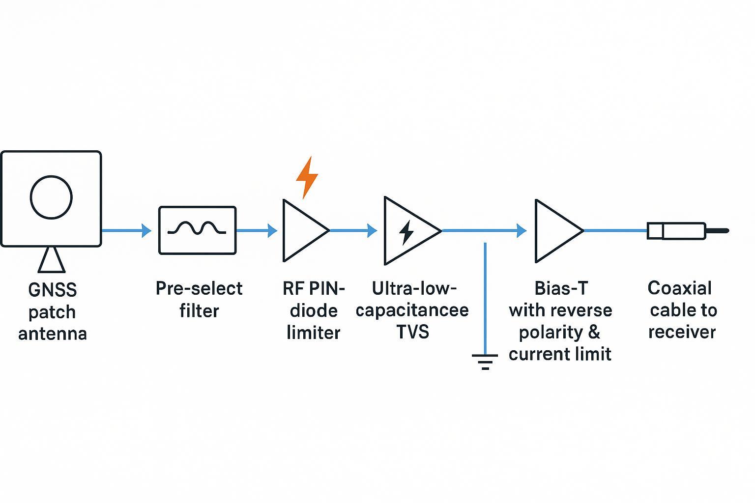
In practical terms, GNSS antenna burnout protection is the set of RF and transient safeguards placed before the first LNA stage and along the DC bias path so that out‑of‑band transmitters, ESD, lightning‑induced surges, or wiring faults can’t permanently damage or silently de‑tune the front end — the hardware-survival companion to the active interference rejection in our anti-jamming GNSS antenna guide. A robust stack typically includes a pre‑select bandpass filter, an RF limiter, ultra‑low‑capacitance TVS to chassis, optional GDT for high‑energy events, and DC protections such as reverse‑polarity and current limiting.
Two quick reference points help frame expectations:
-
Pre‑LNA filtering trades a small insertion loss for much higher overload resilience. The u‑blox GNSS antenna application note explains that placing the LNA after a SAW filter reduces sensitivity by roughly a dB but raises the maximum tolerable input power significantly, which is often the right trade in co‑sited RF environments common on drones. See the discussion in the u‑blox document under antenna front‑end topologies in the u‑blox GNSS Antennas application note.pdf).
-
Aviation installations sometimes reference explicit survivability language. A mirrored excerpt of ARINC 743A mentions that preamplifier burnout protection should withstand a continuous‑wave carrier of 30 dBm without damage. Treat that mirror as informative guidance and consult official ARINC publications for certification decisions. Source: ARINC 743A‑4 mirrored excerpt.
Why protection matters to RTK on drones
From an RTK perspective, burnout and near‑burnout behavior surface as elevated noise figure, clipping in the first stages, or both. The results are visible on your charts: lower C/N0, delayed time to first fix, more frequent cycle slips, and a jitterier baseline. In plain terms, the autopilot sees a shakier ruler for position and heading. How big a hit is that in the air? Think of a consistent 0.6–1.0 dB C/N0 loss across your tracked satellites. On a good day you might still resolve; on a marginal day near urban backscatter or a shipborne radar sweep, your fix ratio falls off a cliff.
When you validate in the lab, the pattern is repeatable. Interferer sweeps raise AGC, squeeze tracking loops, and you start losing carrier phase lock at powers you previously tolerated. A useful primer on structuring GNSS interference tests, from simulators to analyzers, is the compact Rohde & Schwarz satellite navigation pocket guide, which outlines measurement setups and receiver vulnerabilities relevant to these checks.
Common engineering mistakes that cause burnout or hidden desense
Most of the root causes I see in UAV integrations are avoidable. Teams place the GNSS puck too close to a high‑power video or telemetry transmitter on carbon‑fiber without a proper bonded ground plane; they choose a low‑cost active patch with no pre‑LNA SAW or limiter; they provide no clear surge return to chassis at the antenna or bulkhead; they power the antenna from a noisy rail without current limiting or reverse‑polarity protection; and they skip ESD and CW overload validation that would have caught marginal behavior long before field trials.
The protection stack explained
The goal is to shunt energy you do not want and pass the signals you do, with minimal penalty to noise figure and group delay. Here is the stack I recommend and why each element earns its keep.
Pre‑LNA SAW or ceramic bandpass filter
This is your first bouncer at the door. A pre‑select filter rejects strong out‑of‑band transmitters (LTE, Wi‑Fi, telemetry) before they ever hit the LNA. You pay a small insertion‑loss tax, but you prevent the LNA from saturating or creating intermodulation products. The tradeoff is well captured in the u‑blox GNSS antennas application note.pdf). In practice on UAVs, the extra margin against video links and 900 MHz telemetry is worth far more than the fraction of a dB you give up.
RF limiter using PIN diodes
A PIN‑diode limiter conducts once input power crosses a threshold, shunting RF to ground to protect the fragile LNA junctions. Selection focuses on low insertion loss at L1/L2/L5, a soft knee that clamps before the LNA damage point, fast recovery, and robust power handling. For a concise design overview of limiters used to protect receiver front ends, see the article from MACOM on protecting sensitive circuits with diodes in Designing with diodes to protect RF front ends.
Ultra‑low‑capacitance TVS to chassis and optional GDT at the bulkhead
ESD and lightning‑induced transients couple onto exterior connectors and enclosures. A TVS diode with very low capacitance clamps nanosecond events with minimal RF loading; target sub‑pF class devices and provide a short, low‑inductance path to chassis. In high‑surge installations such as mast‑mounted antennas or long cable runs, a gas discharge tube at the bulkhead adds energy‑handling headroom. The selection problem is to meet the IEC 61000‑4‑2 system‑level ESD tests while keeping capacitance low enough that the part doesn’t load the RF path; see the IEC 61000‑4‑2 overview for test levels and waveforms.
DC‑side protections and bias‑T current limiting
Active antennas die from DC faults, too. Provide reverse‑polarity protection, a clamp for overvoltage events, and a current limit in the bias‑T set comfortably above nominal draw. This prevents a mis‑wired harness or a sputtering connector from turning your LNA into a fuse.
Protection element | Primary role | Typical added loss | Selection notes | Example evidence reference |
|---|---|---|---|---|
Pre‑LNA SAW filter | Reject out‑of‑band energy before LNA | ~0.3–0.6 dB | Pick passband for L1/L2/L5, maximize rejection vs onboard TX | ETSI EN 303 413 blocking and out‑of‑band immunity limits |
PIN‑diode RF limiter | Clamp high RF peaks to protect LNA | ~0.1–0.3 dB | Low IL at GNSS bands, threshold below LNA damage, fast recovery | MACOM limiter overview: protecting RF front ends |
Ultra‑low‑C TVS | ESD clamp to chassis with minimal RF loading | ~0.0–0.2 dB | ≤0.5 pF capacitance class, shortest path to chassis | IEC 61000‑4‑2 system‑level ESD test levels |
Optional GDT at bulkhead | High‑energy surge shunt to chassis | N/A when at bulkhead | Use for outdoor masts or long cables; ensure bonding | General surge practice, see DO‑160 lightning context below |
DC reverse/OVP and current limit | Prevent damage from wiring or rail faults | 0 dB in RF path | Set current limit above antenna draw with margin | DO‑160 systems thinking for transients, below |
Component selection and noise figure tradeoffs
Engineers often ask, “What’s the real cost of adding protection?” Here’s a compact way to think about it. If your pre‑LNA protection stack adds 0.6 dB insertion loss ahead of a low‑NF first stage, your cascaded NF rises by roughly the same amount. C/N0 typically moves 1:1 with NF, so expect about a 0.6 dB drop in reported carrier‑to‑noise. In exchange, you gain headroom when the onboard radio chatters or a nearby tower blares. In my experience on drones with crowded payload bays, that trade pencils out immediately in fewer cycle slips and steadier fixes.
There are cases where a passive antenna plus a high‑quality receiver LNA is sufficient, especially on large airframes with generous spacing and clean power. But once you pack a VTX, telemetry, multiple cameras, companion compute, and DC/DC converters into a compact quadcopter, pre‑LNA filtering and limiting stop being optional.
For a sanity check on survivability expectations and test categories, align your lab plan with the spirit of aviation standards. For radiated susceptibility and conducted exposure, study the frameworks in RTCA DO‑160 Section 20 and Section 22 as summarized in accessible overviews like Keystone Compliance on DO‑160 susceptibility and direct effects and their lightning direct effects summary. They won’t pick your parts for you, but they will clarify waveforms, levels, and pass/fail thinking.
UAV integration checklist engineers actually use
-
Mount the GNSS antenna at the top‑center of the airframe on a bonded metal ground plate; if the deck is carbon fiber, add a copper or aluminum plate firmly bonded to chassis.
-
Maintain physical separation from high‑power transmitters on the platform. As a starting heuristic, keep roughly a quarter to a half wavelength at the interfering frequency and validate on your airframe.
-
Route GNSS coax away from ESCs, DC/DC converters, and high‑current bundles; use shielded low‑loss cable and torque connectors properly.
-
Select an active antenna or front end with a documented pre‑LNA SAW and evidence of ESD and surge provisions; verify insertion loss, gain, and NF impacts.
-
Provide a defined surge path: TVS to chassis with minimal inductance near the connector; consider a GDT at the bulkhead for long runs outdoors.
-
Power the antenna from a quiet rail with reverse‑polarity protection, a clamp for overvoltage events, and a bias‑T current limit set above nominal draw.
-
Add firmware or telemetry monitors when available: track GNSS AGC movements, LNA supply current, and sudden fleet‑wide drops in median C/N0; alert when thresholds trip.
-
Validate early with bench interferer sweeps, IEC 61000‑4‑2 ESD checks at accessible surfaces, and controlled flight A/B trials.
Validation and test procedures that catch problems before flight
Bench first, then field. That discipline has saved us more than once.
-
CW overload sweep on the bench: Combine a GNSS simulator or sky‑view splitter with a signal generator injecting a continuous‑wave interferer near expected onboard transmit frequencies. Step power in small increments and log C/N0 deltas, AGC, and loss‑of‑lock thresholds with and without the protection stack. The Rohde & Schwarz satellite navigation pocket guide is a handy field reference for configuring such measurements.
-
ESD checks to system‑level standards: Apply IEC 61000‑4‑2 contact and air discharges to the antenna connector shell and exposed metal, watching for permanent performance shifts. Level 4 calls out ±8 kV contact and ±15 kV air with defined waveforms and repetition. See the IEC 61000‑4‑2 overview with test levels to ground your setup.
-
DO‑160 alignment for aircraft exposure: For programs with aviation aspirations, plan your conducted and radiated tests to map onto DO‑160 Section 20 and Section 22 categories, using overviews like Keystone’s DO‑160 susceptibility summary to communicate intent with stakeholders and test labs.
-
Flight A/B procedure on the platform: Mount a controllable interferer the aircraft already carries (for example, a 2.4 GHz video link) at two separations from the GNSS antenna. Fly two 20‑minute hovers or loiter patterns per condition. Log raw GNSS and RTK engine metrics: TTFF, median C/N0 per band, fix ratio over the window, cycle‑slip counts, and 95% baseline deviation. Repeat after swapping to a protected front end to isolate the stack’s impact.
Real‑world A and B scenario from a drone program
Here’s one representative test from last season on a 1.5 kg quadcopter used for photogrammetry. We instrumented the platform with logging for GNSS raw measurements and RTK engine states and used the existing 2.4 GHz video transmitter as the controllable interferer at +33 dBm.
-
Configuration A, short separation and minimal protection: The VTX whip sat roughly 8 cm from the active GNSS puck, which used only a basic input match and LNA. Across two 20‑minute flights, median L1 C/N0 fell 1.8–2.2 dB compared to clean‑bench baselines when the link was active; TTFF stretched by about 30–40 s after power cycles in the field; RTK fix ratio dropped to the 70–78% range; and we counted 18–25 cycle slips per flight. The 95% baseline deviation widened by roughly 35%.
-
Configuration B, increased separation and protected front end: We moved the VTX to give ~22 cm separation and swapped to a front end with pre‑LNA SAW, a low‑IL PIN‑diode limiter, and a sub‑pF TVS to chassis at the bulkhead. In the same conditions, median L1 C/N0 loss was held to about 0.6–0.8 dB, TTFF returned to near‑bench behavior, RTK fix ratio climbed into the 92–96% band, and cycle slips dropped to 4–7 per flight. Baseline deviation tightened accordingly.
The point isn’t that your numbers will match line‑for‑line; it’s that modest insertion‑loss penalties from protection are swamped by stability gains once you include real onboard transmitters. If you’re thinking, “Couldn’t I just move the transmitter?”—you should, and then still protect the front end for ESD, surges, and unknowns.
Key takeaways for teams shipping drones with RTK
Burnout isn’t always a dramatic failure. It often shows up as a quiet NF increase and a temperamental RTK engine that fails when payloads change or the RF neighborhood gets busy. A small pre‑LNA insertion loss paired with a limiter and a sub‑pF TVS commonly buys back far more availability than it costs. Validate on the bench with interferer sweeps and ESD, then confirm in flight with separation A/Bs. Align test severity and pass criteria with DO‑160 style thinking so program stakeholders understand why you made the trade. And log more than positions—watch AGC, LNA supply current if available, and C/N0 distributions to catch early signs of damage.
FAQ
How do I know if my active antenna actually has burnout protection
Look for an explicit pre‑LNA SAW or ceramic filter in the datasheet and any mention of input limiting or surge handling. Many vendors publish at least ESD ratings or pre‑filter notes. For example, Tallysman lists 15 kV ESD protection on some models and highlights pre‑filter options on others. See the ESD callout in the Tallysman TW1721 datasheet and a pre‑filtered single‑band example on the Tallysman TW3102 product page.
Will a pre‑LNA filter ruin my sensitivity on low‑elevation satellites
Not if you choose carefully. A well‑matched SAW or ceramic filter adds a fraction of a dB of loss. In exchange, you avoid entering non‑linear operation under nearby transmitters. In practice on small drones, the improved linearity and immunity to saturation usually yield better effective tracking on the edge cases that matter for RTK.
Is there any real product evidence that pre‑filters and protection help
Yes. Multiple vendors document pre‑filters, multi‑stage LNAs, and surge provisions in product literature. Taoglas, for instance, shows SAW/LNA/SAW/LNA topologies in front‑end modules and active antennas intended to reject out‑of‑band signals. See the architecture examples in the Taoglas TFM.110A front end datasheet and the dual‑band front end AGVLBD258A datasheet.
How should I treat surge and lightning on small UAVs
For small airframes, prioritize a very short TVS path from the antenna connector shell to chassis. If your installation involves exposed masts or long coax, consider a bulkhead GDT for energy handling and coordinate test levels with your lab per DO‑160 Section 22 lightning‑induced transients. For orientation, review overviews such as Keystone’s summary of lightning direct effects considerations.
What if I cannot move the transmitter farther away
Then optimize everything else: add or enlarge the bonded ground plate under the GNSS antenna, turn the front end into a protected topology with pre‑LNA SAW and a low‑IL limiter, ensure coax routing is clean, and run the A/B validation to quantify your gains. Even small separation increases, cleaner return paths, and a proper limiter can turn an unreliable setup into a shippable one.
Next steps
If you are selecting hardware now, shortlist protected active antennas or front‑end modules that document pre‑LNA filtering, limiting, and ESD handling, and run the bench and flight validations outlined above. As a neutral reference point for advanced GNSS antenna systems used in defense, aviation, and infrastructure, GNSource can be used to evaluate form factors and integration options alongside the protection guidance described here.
References mentioned in context above are intentionally minimal and authoritative to keep the focus on engineering practice: u‑blox GNSS antenna integration guidance, the Rohde & Schwarz pocket guide for testing setups, mirrored ARINC commentary on burnout expectations, DO‑160 overviews for susceptibility and lightning, and vendor datasheets and pages from Tallysman and Taoglas that surface pre‑filters and ESD provisions. Where certification is in scope, consult the official standards and manufacturer PDFs for definitive values and language.