I’ve watched solid RTK systems fall apart after a seemingly minor airframe change: move the antenna 30 mm, skip a proper ground plane, accept a few centimeters of cable-length mismatch—and suddenly fixes bounce between float and fixed, and your nulls turn shallow the moment a cheap jammer lights up downrange. The good news: CRPA performance on UAVs and vehicles is predictable if you respect placement, ground plane geometry, and cabling discipline. Here’s the playbook I use on production integrations.
What Makes CRPA Different (and Why RTK Cares)
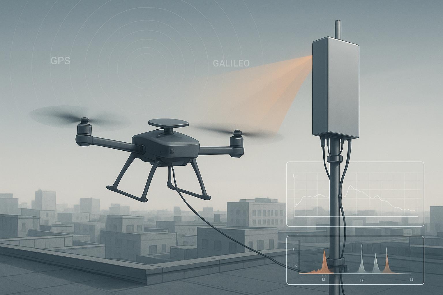
A Controlled Reception Pattern Antenna (CRPA) — the anti-jamming workhorse covered in our CRPA anti-jamming guide — is an array of GNSS elements whose signals are combined adaptively to steer nulls toward interferers while preserving satellites. That only works when per‑element phase and amplitude are well controlled. Small inter‑element phase errors distort the array response and reduce achievable null depth. In other words, sloppy cabling or a detuned mount leaks energy where you’re trying to place a deep null—and RTK availability craters under interference.
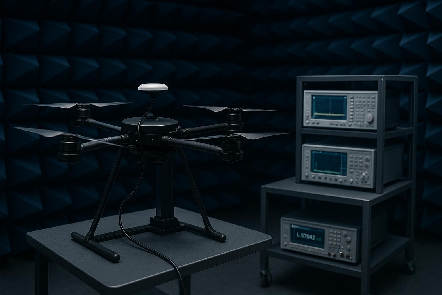
For context on professional calibration and test methods, Safran’s overview of over‑the‑air wavefront simulation lays out how engineers verify phase alignment and null steering in the lab; see the methods in the Engineer’s Guide to CRPA Testing from Safran Navigation & Timing. I also keep in mind the system‑level benchmarks referenced in the GPS World Simulator Buyers Guide, which describe Spirent’s multi‑element CRPA test capabilities and the null depths achievable in controlled environments. These resources help set realistic expectations in the field while reminding us that on‑airframe results are usually a notch below chamber demos.
-
According to the detailed workflows in the Engineer’s Guide to CRPA Testing by Safran (2024), precise per‑element calibration and OTA verification are essential to validate null steering.
-
System‑level benchmarks noted in the GPS World Simulator Buyers Guide (2021) outline multi‑element CRPA test capabilities (e.g., Spirent GSS9000) used to demonstrate 40–50 dB nulls under controlled conditions.
CRPA UAV Placement, Ground Plane, and Cabling—The Rules I Trust
This is where “CRPA UAV placement ground plane cabling” stops being a keyword and becomes a checklist you can build into CAD, harness drawings, and PAT.
Placement
-
Favor top‑center mounting for a clean sky view and consistent azimuth coverage. Align boresight with vehicle forward axis to simplify INS/RTK referencing.
-
Keep the array at least ~0.5λ away from large conductive edges and control surfaces at the lowest band of interest; for L1, that means roughly 9–10 cm minimum.
-
On multirotors, a 10–20 cm elevation on dielectric standoffs reduces coupling into the fuselage and rotors.
Ground plane (GP)
-
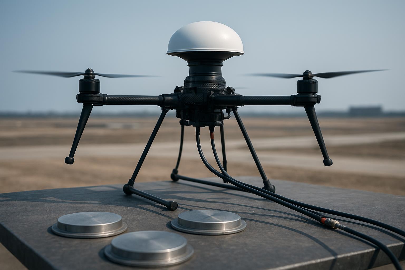
Implement an intentional, conductive ground plane on composite/carbon fuselages. For RHCP patches and most CRPA radomes, a GP stabilizes patterns, improves axial ratio, and controls multipath.
-
For L1-centric designs, u‑blox’s application note recommends 50–70 mm ground planes for single patches; arrays are more sensitive and benefit from larger diameters. Use ≥0.7λ diameter at the primary band as a conservative rule of thumb (≈13–14 cm at L1, ≈17–18 cm at L2/L5). Validate on your platform with OTA checks. See the guidance in the u‑blox GNSS Antennas Application Note (UBX‑15030289).pdf).
-
Accessory references like the Calian/Tallysman Embedded Antennas Reference Guide v7.0 (2024) and their 100 mm aluminum GP accessory indicate practical baseline sizes and the performance gain you recover with proper planes.
-
Prefer solid plates or high‑coverage perforated metal (>70% conductive surface). Maintain continuous bonding if the vehicle chassis acts as a common reference—but isolate from noisy electronics cavities.
Cabling and connectors
-
Use phase‑stable coax assemblies for element feeds. General‑purpose LMR may meet insertion loss goals but drifts more in phase with temperature. Times Microwave documents PhaseTrack‑class cables designed for linear, low phase change vs. temperature; see the engineering background in Coax Cables Powering Modern Array Radars (Times Microwave).
-
Match element cable lengths tightly. As a planning number, target ≤±5 mm (≈±5° at L1 using a free‑space approximation). Tighter is better for deep nulls. Verify with a VNA or a calibrated phase meter at in‑band tones.
-
Route away from ESCs, DC‑DC converters, and high‑current harnesses. Where you must cross, do it at right angles and add ferrite chokes near feedthroughs.
-
Use torque‑controlled, sealed threaded connectors (SMA/TNC) with O‑rings/gaskets. Follow connector datasheets and re‑torque after thermal/vibration cycles. For reference ranges and best practices, see Times Microwave’s connector torque guidance.
I’ve found that when teams institutionalize those four bullets into design rules, CRPAs behave consistently—and anti‑jam gains stop evaporating after the first hot‑cold soak or airframe revision.
A Realistic Test Comparison on a Carbon Quadrotor
Scenario: 6‑element L1/L2 CRPA on a carbon‑fiber quadrotor tasked with centimeter‑level RTK surveying in semi‑urban airspace.
Baseline (problem integration)
-
Array mounted flush to a carbon dorsal shell with no metallized GP.
-
Element cables mismatched by up to ±5 cm; general‑purpose coax; connectors hand‑tight.
-
Bench S11 looked passable, but field tests showed intermittent float fixes and shallow nulls against a 10 dB‑over‑noise swept jammer.
Remediation (integration corrections)
-
Add a lightweight ≈0.7λ ground plane at L1 (perforated aluminum honeycomb, >70% conductive coverage), bonded to a clean reference.
-
Elevate the array by ~12 cm on dielectric standoffs to clear the carbon shell and reduce multipath.
-
Rebuild the harness with phase‑stable coax; match element electrical lengths to within ±5 mm; add ferrite chokes near bulkheads.
-
Replace connectors with IP67 threaded parts; torque per datasheet; add locking features compatible with seals.
Expected outcome (conservative, consistent with vendor test ranges and field practice)
-
Null depth improvement: +20–30 dB compared to baseline after recalibration.
-
RTK fix behavior: sustained >95% fixed in test loops; CEP tightening from ~0.8 m (float/biased) to <0.08 m (fixed) in dual‑frequency RTK under benign interference.
Think of it this way: the ground plane stabilized the radiation environment, elevation reduced fuselage coupling, and phase‑matched, stable cabling returned coherent combining—so the adaptive null has phase “grip.”
Common Integration Mistakes That Break CRPA
-
Undersized or missing ground plane on composites, leading to pattern distortion and multipath‑driven bias.
-
Unmatched element cable lengths or non‑phase‑stable coax, causing phase skew that collapses null depth.
-
Coax routed alongside power/ESC harnesses, raising the noise floor and creating load‑dependent SNR dips.
-
Relying on bare carbon fiber (no metallization/foil) under the array, detuning and attenuating signals unpredictably.
-
Loose or unsealed connectors that shift phase under vibration or ingest moisture over time.
Practical Improvement Checklist (Production‑Friendly)
I keep the phrase “CRPA UAV placement ground plane cabling” at the top of the build sheet so manufacturing knows these are not optional. Two quick‑reference tables cover 80% of what trips teams up.
Cable match quick reference | L1 (1575.42 MHz) | L2 (1227.60 MHz) |
|---|---|---|
1° phase difference ≈ | 0.53 mm | 0.68 mm |
5° ≈ | 2.7 mm | 3.4 mm |
10° ≈ | 5.3 mm | 6.8 mm |
Installation target (per element pair) | ≤±5° (≤±2.7 mm) | ≤±5° (≤±3.4 mm) |
Connector & sealing checklist | Guidance |
|---|---|
Connector type | Threaded SMA/TNC with IP67 sealing (O‑rings/gaskets) |
Torque | Per connector datasheet; use a torque wrench; re‑check after environmental cycling |
Locking | Thread‑lock or lock washers as allowed by materials/seals |
Strain relief | Provide at bulkheads and moving interfaces; dress cables to avoid fretting |
Environmental | Verify sealing after vibration/thermal soak; inspect O‑rings for nicks/flat‑spots |
Micro‑example (neutral): If you don’t have in‑house cable/mount fabrication, GNSource can supply phase‑matched harnesses and ground‑plane kits built to your footprint—useful when you need consistent mm‑level matching across production lots.
Calibration and Verification Workflow You Can Repeat
Factory/lab
- Start with an OTA or near‑field wavefront setup to calibrate per‑element phase/amplitude and to verify null steering under controlled interferers. The step‑by‑step approach in the Safran Engineer’s Guide to CRPA Testing describes how teams validate this before airframe installation.
On‑platform field checks
-
Run a sky survey on a clear day to map C/N0 by azimuth/elevation and confirm the array isn’t shadowed by airframe geometry. A simple azimuth sweep from a turntable or ground taxi can reveal gross asymmetries.
-
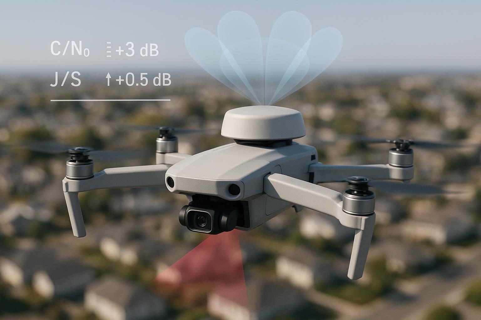
Conduct a controlled jamming sweep in a legal RF test range. Record null depth (dB), J/S margins, and RTK fix percentage across runs. Benchmarks quoted in the GPS World buyers guide reference to Spirent provide a ceiling; your on‑airframe results should be consistent proportionally.
-
Log environmental cycles (temperature, vibration) and re‑verify connector torque and phase balance after stress.
Production acceptance test (PAT) — pass/fail snapshot
Test item | Target | Pass/fail gate |
|---|---|---|
Return loss (S11) per element | ≤ −10 to −14 dB in‑band (per vendor) | All elements within spec |
Phase balance (L1 CW) | ≤±5° RMS across elements | Meets or better |
Amplitude balance | ≤±1 dB RMS | Meets or better |
Nulling check (range test) | Formation against controlled interferer | ≥ specified dB relative to baseline |
Connector torque & seals | Per datasheet; IP67 visual | All fasteners in range; seals intact |
Harness routing QA | Clear of high‑current paths; secured | Visual pass |
When something fails, isolate quickly: swap in a known‑good matched harness, measure phase on each port, and re‑run the azimuth sweep before touching the mount. You’ll save hours chasing ghosts.
Short FAQ for Engineering Leads
How big should the ground plane be on a compact UAV?
- For arrays over composites, start with ≥0.7λ at your primary band (≈13–14 cm at L1) and verify. Smaller planes can work but expect pattern instability and weaker nulls without careful testing. See the size sensitivity examples in the u‑blox GNSS Antennas note.pdf) for single patches; arrays are at least as sensitive.
Do helicals reduce ground‑plane dependence for CRPA?
- Single helical elements can be more tolerant, but CRPA pattern control still benefits from a defined conductive reference. If your array uses helicals under a radome, validate with the same GP/elevation discipline.
What’s an acceptable element phase mismatch for anti‑jam work?
- As a design target, ≤±5° at L1 (≈±2.7 mm free‑space equivalent) keeps nulling predictable. Tighter is better. Confirm with in‑band phase measurements, not just ruler lengths.
We use carbon fiber everywhere—is metallization mandatory?
- If you want predictable patterns and nulls: effectively yes. A bonded foil or thin plate under the radome, isolated from noisy cavities, dramatically reduces surprises.
When should I re‑calibrate?
- After any mount change, harness replacement, or environmental event that could shift phase (moisture ingress, connector replacement, vibration damage). Schedule periodic checks based on hours/cycles and temperature exposure.
Wrap‑up
CRPA performance on UAVs and vehicles is fragile if you neglect fundamentals and robust if you bake them into design control: disciplined placement, a real ground plane, and phase‑stable, matched cabling. Lock those in, verify with repeatable lab and range tests, and your RTK won’t fall to pieces the next time someone moves a bracket. If you need standardized GP templates or phase‑matched harnesses for your platform, talk to your antenna vendor or integrator to source build‑to‑print kits.