I’ve lost count of how many times a team brought me a top-tier RTK receiver and still couldn’t hold a fixed solution once the drone lifted off or the test car left the lot. Nine times out of ten, the issue wasn’t the receiver. It was the antenna choice, the mount, or the cabling. Here’s the deal: on dynamic platforms, the antenna is your front end, and whatever it doesn’t do well (phase-center stability, polarization purity, multipath rejection) shows up downstream as slower convergence, jittery baselines, and fragile fixes.
The recurring problem: great receiver, inconsistent RTK in the field
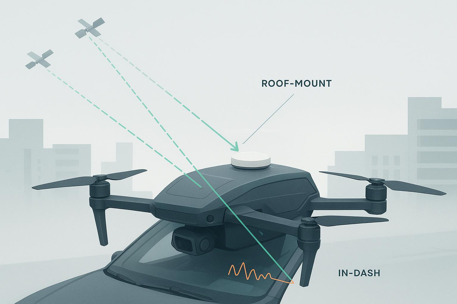
Two recent examples: a 5 kg quadcopter that floated between fixed and float whenever it accelerated, and a roof-mounted autonomy rig that showed 25–33 dB-Hz on satellites that should have been 40+ dB-Hz. Both receivers were fine. The UAV’s light radome plus a flexy mast amplified vibration and changed the apparent phase center as the disk “breathed.” The car had a nice antenna—but it sat near a crossbar and shark-fin housing that lit up multipath.
If you’re seeing long time-to-first-fix (TTFF), a low fixed-RTK ratio, or C/N0 that sags at mid–high elevations, start with the antenna system, not the receiver.
The essentials you can’t skip: PCO/PCV, axial ratio, multipath, and C/N0
Think of the antenna’s electrical phase center like the balance point of a spinning top—it shifts slightly with frequency and signal angle. That’s phase center offset (PCO) and phase center variation (PCV). For carrier-phase RTK, millimeters matter. NovAtel’s antenna and calibration guidance explains how PCO/PCV differences map directly into centimeter-level biases if you ignore them or enter the wrong model in your rover/base configuration; geodetic-grade antennas and correct calibrations are recommended for RTK-grade work, especially as you chase the last centimeters of accuracy (see NovAtel’s reception basics and calibration notes, 2023–2025). For reference, NGS/NRCan workflows (OPUS/CSRS‑PPP) require correct antenna+radome models and apply calibration files; skipping that step degrades solutions and can bias troposphere estimates, as their public documentation notes (2018–2026).
Axial ratio is your proxy for circular polarization purity. The closer to 0 dB the better; ≤3 dB across a wide field-of-view is a practical target for dynamic platforms. Poor axial ratio allows cross-polarized energy and multipath to leak in.
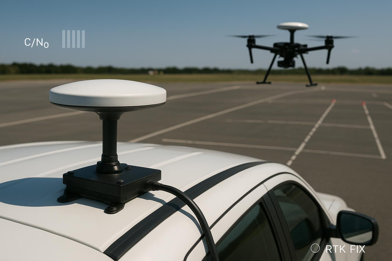
What’s “good” C/N0? As a practical yardstick across clear-sky tests: 45–50+ dB‑Hz at high elevation is healthy on well-installed systems; 35–45 dB‑Hz is common and usable; 30–35 dB‑Hz is marginal and often vulnerable to cycle slips; sustained <30 dB‑Hz signals indicate real trouble. Vendor docs from NovAtel and Trimble describe how ionospheric scintillation causes rapid C/N0 swings and why low-elevation tracking is inherently noisier. Use those patterns diagnostically rather than chasing a single magic threshold.
Authoritative references: NovAtel “Reception” and scintillation notes (2024–2025); Trimble receiver documentation and plotting guidance (2018/2026); NGS OPUS About and NRCan CSRS‑PPP info (2018–2026).
Why this dominates RTK on vehicles and drones
RTK error budgets are unforgiving. Every extra millimeter of unmodeled PCO/PCV, each dB of lost C/N0 from a poor ground plane or cable, and every extra reflection from a roof bar or UAV boom increase ambiguity churn. More tracked constellations and frequencies improve geometry and error observability, so multi‑band, multi‑constellation antennas typically converge faster and re‑fix more reliably in motion. Recent NovAtel and Trimble materials outline how richer frequency sets and corrections lift dynamic performance; you still have to earn it with a clean RF front end and a rigid, phase‑stable mount. For heading, dual‑antenna baselines on compact platforms can deliver sub‑degree results when the baseline is rigid and offsets are entered correctly; Septentrio’s product docs show that even short baselines can work on UAVs when geometry and calibration are sound.
Bottom line: on autonomous systems, the antenna system determines how much of your receiver’s theoretical capability is actually available in the field.
Frequent integration mistakes that kill performance
-
Soft, flex-prone mounts on UAVs that let the disk tilt or resonate, shifting the apparent phase center under thrust.
-
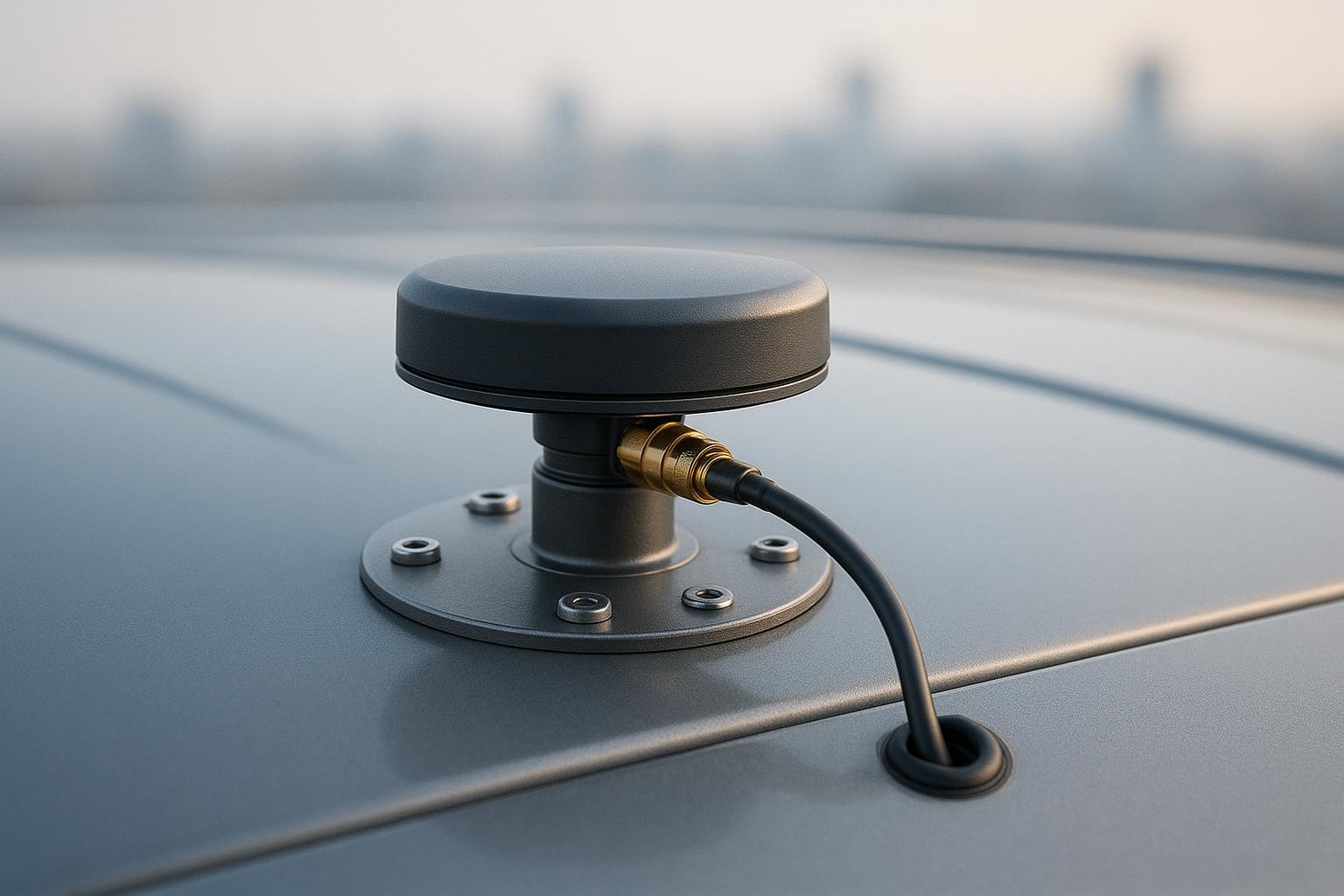
Roof placements too close to bars, camera pods, or shark-fin housings—multipath city. Center of the largest flat ground plane is usually best.
-
High-loss coax (long RG‑174 or thin mini coax) that eats LNA headroom; adapters and T’s sprinkled through the run.
-
No ground plane under compact patches; or mixed radomes without updating the antenna model in firmware, breaking PCV consistency.
-
Poor cable routing alongside VTX, ESCs, or DC‑DC converters; no ferrites or shields; floating grounds.
-
Firmware metadata mismatches: wrong antenna type/radome code, no cable-loss entry, or stale receiver firmware.
-
Dual-antenna baselines mounted on separate flexures, then blamed for heading “jitter.”
-
Treating anti-jam CRPA as a drop-in cure-all without planning array calibration, power, and roof clearance.
Practical improvement checklist (do this before your next flight/drive)
-
Mounting: place the antenna at roof center or at least 0.5 m from edges/obstructions; use a rigid bracket and, for small patches, a proper ground plane. Verify <0.5 mm mount wobble under expected vibration.
-
Cabling: budget loss using Times Microwave charts; keep adapters to a minimum; prefer LMR‑240 for moderate runs and LMR‑400 for long runs. Add 0.1–0.3 dB per connector in the budget.
-
Power/RF hygiene: separate GNSS coax from high-current lines; cross at 90° when necessary; add clip-on ferrites near the receiver and at bulkheads.
-
Antenna metadata: set correct antenna+radome model and enter cable loss/LNA power settings where supported; keep rover/base models consistent.
-
Dual‑antenna: mount both on a rigid beam; measure the baseline vector in the vehicle frame; enter lever arms carefully and verify sign conventions.
-
Validation cadence: log C/N0 by band/elevation, RTK fix ratio, TTFF, and positional RMS over repeat routes; change one thing at a time.
A reproducible A/B test on a UAV: what changed and why
Setup
-
Platform: 5 kg quadcopter; survey‑grade, multi‑band receiver; network RTK via NTRIP.
-
Antenna A: geodetic‑grade, low‑PCV patch on a rigid plate; Antenna B: lighter multi‑band patch with higher stated PCV and slightly worse axial ratio.
-
Controls: same cable type/length (LMR‑240, 2.0 m), identical mount location; 10 km route at 50–120 m AGL; log at 5 Hz.
Representative results (mixed obstruction day, light winds):
Metric | Antenna A | Antenna B |
|---|---|---|
Mean C/N0 (L1/E1 high elevation) | 46.8 dB‑Hz | 44.1 dB‑Hz |
Mean C/N0 (L5/E5a low elevation 15–25°) | 39.2 dB‑Hz | 35.6 dB‑Hz |
RTK fixed ratio (entire route) | 94.7% | 82.3% |
TTFF to fixed RTK after power‑up | 21 s | 38 s |
1 Hz positional RMS over repeat passes | 1.8 cm | 3.4 cm |
Interpretation
- The A antenna’s better axial ratio and lower PCV preserved low‑elevation C/N0 and reduced cycle slips during accelerations, which lifted the fixed‑RTK ratio by ~12 points and cut TTFF nearly in half. The RMS repeatability improved accordingly. This pattern mirrors what NovAtel and Trimble describe about polarization/multipath impacts and phase‑center handling: geometry helps, but front‑end quality and stability decide whether ambiguities stay fixed in motion.
A neutral planning example (GNSource)
- During vehicle/UAV planning, I’ll scan datasheets for axial ratio (target ≤3 dB across the FOV), LNA gain (≈34–36 dB typical for survey/timing units), and noise figure (≤2 dB). When Tx/Rx coexist on the same mast (for example, BeiDou RDSS or other L‑/S‑band radios near GNSS), I also check whether the antenna and radome can coexist mechanically and electrically without saturating the LNA or coupling energy into the feed. One public reference that helps contextualize coexistence hardware on platform masts is GNSource’s BDS Short Message (RDSS Tx/Rx) page, which shows how single‑cable Tx/Rx variants and radome form factors drive mounting and grounding decisions; use it as a reference point, then validate on your platform with spectrum snapshots and on-vehicle C/N0 logging. Link: BDS Short Message Antennas — RDSS Tx/Rx. Treat the datasheet as a starting hypothesis and prove it in your own tests.
Integration settings that silently bias your results
Corrections and logging
NTRIP.CASTER = your-provider.example.com:2101
    NTRIP.MOUNT   = VRS_MSM5
    CORR.AGE_MAX  = 5 s
    LOG           = RAW, RANGECMP, SNR @ 5 Hz
Antenna metadata and cable loss
ANT.TYPE   = GEOD_LOWPCV_XXX  ; use exact model/radome code
    ANT.ARP    = 0.000 0.000 0.045 ; ARP above vehicle frame origin (m)
    CABLE.LOSS = 0.52 dB          ; e.g., 2.0 m LMR‑240 + 2 connectors
    LNA.POWER  = ON               ; verify DC current draw on bench
Lever arms and baseline
LEVER.IMU->ANT   = +0.120 +0.000 +0.350  ; x,y,z in body frame (m)
    DUAL.BLINE.VEC   = +0.650 +0.000 +0.000  ; baseline for heading (m)
    ORIENT.CONVENTION= FRD                 ; forward-right-down frame
Time sync
PPS.OUT    = 1 Hz, 3.3 V, 10 ms width
    TIME.TAG   = Camera,Lidar via GPIO timestamp
    FW.VERSION = pin to tested build; export config checksum
Notes and sources: The configuration ideas above echo public guidance from NovAtel OEM7 manuals and NGS/NRCan antenna handling practices. Always confirm exact parameter names in your receiver’s documentation.
Key takeaways
-
For GNSS antennas for vehicles and autonomous systems, phase‑center stability, axial ratio, and mount rigidity dominate dynamic RTK outcomes—more than receiver brand.
-
Budget cable loss and connector penalties; preserve LNA headroom with LMR‑240/400 when runs get long.
-
Multi‑band/multi‑constellation tracking shortens convergence and improves re‑fix odds—but only if your RF front end is clean.
-
Validate with a repeatable A/B method: log C/N0 by elevation, RTK fix ratio, TTFF, and pass‑to‑pass RMS; change one variable at a time.
-
Treat anti‑jam/CRPA as a system project with calibration, power, and mounting—not a bolt‑on miracle.
FAQ
Q: Do I really need geodetic‑grade antennas for small UAVs? A: If you need consistent centimeter‑grade RTK while maneuvering, yes—especially when low‑elevation tracking matters. Lower PCV and better axial ratio pay off in fix stability. See NovAtel’s antenna calibration notes and NGS guidance on model correctness for context.
Q: What’s an acceptable C/N0 target after installation? A: In open sky, expect high‑elevation signals in the high‑40s dB‑Hz and low‑elevation bands in the mid‑ to high‑30s dB‑Hz on a good install. Sustained <30 dB‑Hz on multiple satellites suggests blockage, interference, or excessive loss to troubleshoot.
Q: How long should my dual‑antenna baseline be on a compact rover? A: Longer is better for heading precision, but several modern receivers support small baselines when mounts are rigid and offsets exact. Septentrio documentation is a good primer; verify on your platform with dynamic maneuvers.
Q: When is CRPA justified on a vehicle? A: When jamming/spoofing risk is material to operations. Plan for array calibration, roof clearance, power/weight, and verification. NovAtel’s GAJT materials and Inside GNSS overviews are useful planning references.
Next steps
Run the A/B workflow on your platform, budget your coax properly, and lock antenna metadata across rover and base. If you need custom frequency tuning or a form‑factor adaptation, GNSource can support engineering-led adjustments—validate everything on your vehicle before scaling.
References (selected, public):
-
NovAtel: GNSS reception basics; scintillation; OEM7 manuals; TerraStar comparisons; interference overview. 2023–2025.
-
NGS/NRCan: OPUS About; ANTCAL FAQ; CSRS‑PPP info. 2018–2026. OPUS About ; ANTCAL FAQ ; CSRS‑PPP info
-
Trimble: Receiver documentation and plotting guidance. 2018/2026.
-
Septentrio: Dual‑antenna heading products and manuals; PX4 integration notes. 2020–2026.
-
Times Microwave: LMR coax reference and guide. 2022–2024. LMR coax reference chart ; LMR complete guide