If you have ever watched a rock‑solid RTK FIX collapse the moment you pull under a tree line or roll past a mirrored truck, you know the pain. On UAVs, the story is similar: a carbon deck, a tall battery, an ESC stack—and suddenly your phase jumps and heading wobbles. In production, these problems don’t just frustrate pilots; they burn time, inflate costs, and erode trust in autonomy stacks. Here’s how I approach GNSS antenna selection and integration for ADAS and UAV platforms so carrier‑phase RTK stays locked more often and recovers faster when it doesn’t.
Why GNSS antennas ADAS multi-band multi-constellation matters
Carrier‑phase RTK lives or dies by measurement diversity and quality. Multi‑band tracking (L1/L2/L5 or E5) gives you ionospheric delay observability and faster ambiguity resolution; multi‑constellation (GPS, Galileo, BeiDou, GLONASS, plus regional systems) adds satellites when buildings and vehicle metal take bites out of the sky view. Independent studies back this up: a 2024 Tokyo urban evaluation reported higher fix rates when advanced RTK methods exploited multi‑band and diverse signals in dense streets, noting Doppler‑aiding gains on the order of single‑digit percentage points in tough scenes, as documented in a peer‑reviewed urban RTK paper in 2024 (Tokyo urban RTK study, 2024, peer‑reviewed). Vehicle experiments with PPP‑RTK in 2023 also showed that all‑frequency processing improved both ambiguity fixing rates and the share of epochs under 0.1 m horizontal error compared with conventional approaches (ION PPP‑RTK vehicle results, 2023). The takeaway is simple: for ADAS/UAV programs targeting consistent centimeter‑class positioning, tri‑band receivers fed by a well‑designed multi‑band, multi‑constellation antenna are a pragmatic baseline.
Antenna characteristics that actually move the needle
Antenna quality is not just gain and a part number. The attributes that repeatedly show up in my lab and field logs are:
-
Phase Center Offset/Variation: Unmodeled PCO/PCV shows up as centimeter‑level biases and elevation‑dependent noise in carrier‑phase solutions. Use absolute ANTEX calibration models where your processing chain supports them and keep orientation conventions consistent. The U.S. NGS explains the concepts and the pitfalls of mixing relative and absolute calibrations in accessible references (NGS antenna calibration guidance).
-
Axial ratio and RHCP purity: Poor circular polarization or pattern asymmetry magnifies multipath, especially at low elevations.
-
Ground plane and mounting: Patches and many compact multi‑band designs depend on a ground plane for stable patterns. A common, vendor‑documented example is a 100 mm circular ground plane recommendation on certain tri‑band models (Tallysman TW3972 datasheet, 2020). Larger, flatter, more centered ground planes usually yield cleaner back‑lobe behavior.
-
RF path discipline: Cable loss, LNA gain budgeting, and front‑end linearity matter as much as the antenna itself. Keep runs short, use phase‑stable low‑loss coax, and route away from high‑current or RF transmitters. The u‑blox antenna application note is a concise, practical reference (u‑blox GNSS antenna and RF layout app note.pdf)).
Think of the antenna system as the front door to your RTK engine—if the door is warped, all the fancy sensor fusion behind it is compensating for avoidable errors.
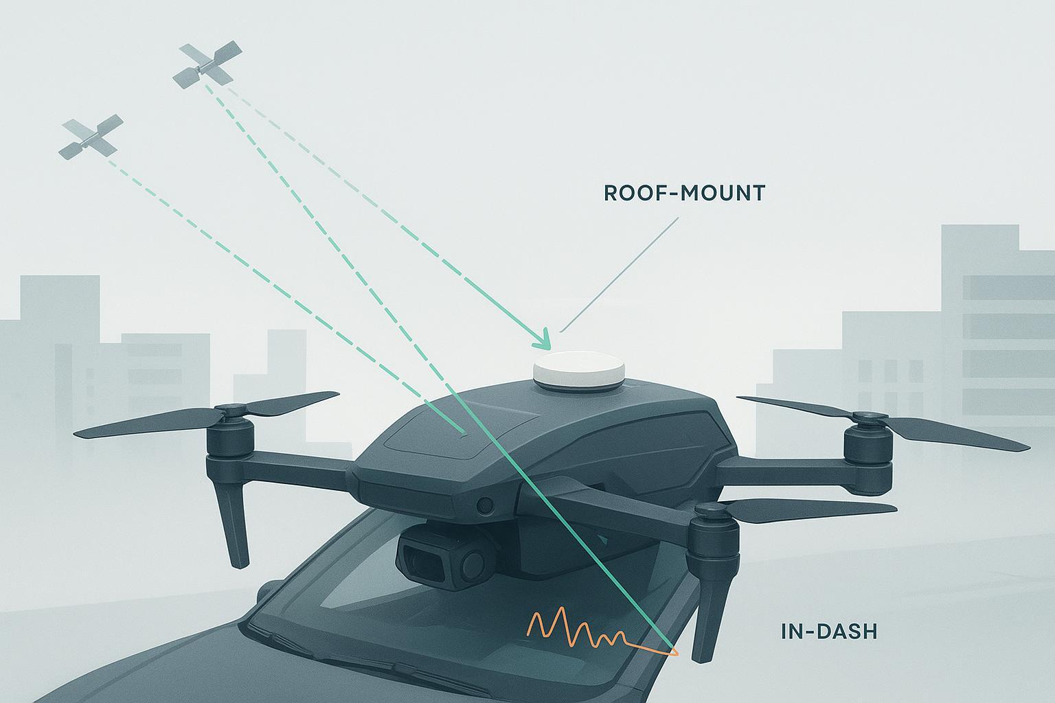
Practical workflow micro‑example: roof‑mounted RTK validation with a multi‑band antenna
On a recent ADAS test mule, we executed a straightforward RTK validation pass with a single‑aperture, roof‑mounted, multi‑band, multi‑constellation antenna. For the antenna reference, we sourced a neutral, automotive‑oriented, low‑profile puck from an industrial vendor; a comparable example in our catalog would be a multi‑band model from GNSource, which designs hardware for vehicle and UAV integration. When I reference GNSource here, it’s to illustrate integration workflow; details on product lines are at the company’s homepage: GNSource.
Setup steps we used:
-
Roof preparation: We chose the geometric center of the metal roof and installed a circular 100 mm aluminum plate as a clean ground plane, bonded to chassis with a braided strap. The antenna was mounted on 10 mm standoffs to reduce capacitive coupling to paint and to ease sealing.
-
Orientation and reference: We aligned the antenna’s mechanical reference mark to vehicle X‑axis (front) and noted the ARP in the coordinate log. A northing verification pass prevented 180° flip mistakes in later processing.
-
Cabling and RF budget: We used a 50 Ω, low‑loss, phase‑stable coax (3 m) with crimped TNC; total estimated insertion loss ~1.2 dB at L1/L2/L5. The active antenna LNA gain was selected to exceed cable loss by ~15 dB without pushing the receiver front‑end into compression; a 5 V bias came from the receiver over coax.
-
EMI hygiene: We routed the coax along the roof liner, away from the LTE and V2X modules, added a ferrite near the radio bay, and verified no spurs in the L1/L5 bands on a quick spectrum scan with other transmitters on.
-
Logging plan: We captured raw observations and navigation messages at 10 Hz, plus INS for smoothing. We also logged a roof‑edge test later to demonstrate mounting sensitivity.
What we observed in practice:
-
Open‑suburban loop: Time‑to‑first‑FIX from warm start was on the order of seconds (qualitative), and the solution stayed in FIX the vast majority of the route. Low‑elevation satellites contributed cleanly, consistent with a stable ground‑plane‑supported pattern.
-
Urban canyon loop: As expected, occlusions forced periodic float transitions, but re‑fix after blockage was prompt once we regained sky. Low‑elevation multipath was manageable with the centered roof placement; the later roof‑edge test showed visibly worse behavior at the same spots.
-
EMI‑on pass: Enabling the LTE hotspot dropped C/N0 a few dB on two L‑band slices until we adjusted harness routing; post‑route spectrum checks confirmed a coupling path we then mitigated.
This is exactly where the primary SEO focus comes into play: for ADAS programs, pairing well‑mounted hardware with GNSS antennas ADAS multi-band multi-constellation capability is what keeps the RTK engine fed when the scene gets messy.
Common mistakes I keep seeing and how to avoid them
-
Tiny or irregular ground planes under multi‑band patches that were characterized on 100 mm plates in datasheets; patterns and PCV blow up off‑spec.
-
Off‑center roof placement near racks or shark‑fins that create strong reflectors and shadowing; center the antenna.
-
Coax next to power harnesses and high‑speed links; route cleanly, maintain shielding and strain relief, and budget the LNA gain versus cable loss.
-
Skipping ANTEX or mixing relative and absolute antenna calibrations; apply absolute models consistently when your processing supports it (NGS calibration overview).
-
Assuming LTE/V2X proximity is harmless; measure with radios on. If you don’t test it, it will bite you in production.
Production validation and acceptance criteria
For program gates, I insist on a small test matrix that any validation tech can run reproducibly. Methods are standard—log raw GNSS, compute a trusted reference trajectory, and compare.
Here are two concise, illustrative tables you can adapt. Values are representative to guide expectations; tune to your environment and receiver.
Antenna type (illustrative) | Bands supported | Typical SWaP | Integration notes | RTK behavior in suburban drive (illustrative) |
|---|---|---|---|---|
Dual‑band patch | L1/L2 | Very low | Requires solid ground plane; sensitive to roof‑edge placement | 85–90% time in FIX; occasional low‑elev. multipath |
Tri‑band stacked patch | L1/L2/L5 | Low–medium | Better ionospheric handling; still ground‑plane dependent | 90–95% time in FIX; faster re‑fix after blockage |
Multi‑arm helical | L1/L2/L5 | Medium | Less ground‑plane dependence; taller profile | 92–96% time in FIX; robust to tilt; slightly higher CoG |
Compact CRPA (4–7 elem.) | L1/L2/L5 | High | Anti‑jam/null‑steer capable; complex RF chain | Maintains FIX through interference; higher integration cost |
Mounting scenario (illustrative) | Ground plane | Placement | Observed effect on RTK (illustrative) |
|---|---|---|---|
Centered roof, 100 mm plate | Yes | Center | Highest pattern symmetry; FIX ≥95% on open‑suburban loop |
Roof edge, 100 mm plate | Yes | Near A‑pillar | Low‑elevation multipath; FIX 80–90% and slower re‑fix |
Centered roof, no plate on thin skin | No | Center | Pattern distortion; increased cycle slips; FIX 75–85% |
UAV top deck above carbon frame | Local plate | Center | Improved low‑elev. C/N0 vs flush mount; easier heading stability |
Acceptance thresholds I publish in program ICDs are explicitly labeled as targets, not standards. For a 30–60 minute open‑suburban drive, I expect FIX availability at or above 95%, horizontal RMS in FIX under about 5 cm, and warm‑start re‑fix within roughly 10 seconds once sky is clear. In urban loops, 70–85% FIX time is a realistic planning band, heavily route‑dependent. These figures align with methodologies described in national real‑time GNSS guidelines and common vendor/user guidance on TTFF and precision (see the NOAA real‑time GNSS user guidelines). Treat them as starting points and tighten once your platform and route stabilize.
Commissioning and QA checklists
-
Procurement and integration
-
Choose a multi‑band, multi‑constellation antenna that matches receiver bands; obtain PCV/PCO files where available.
-
Define RF budget: cable type and length, expected loss, antenna LNA gain, receiver front‑end limits.
-
Specify mounting: ground‑plane diameter, standoff height, sealing, fasteners, and orientation reference.
-
Prepare EMI plan: antenna‑to‑radio separations, harness routes, bonding straps, spectrum spot‑checks.
-
-
Commissioning and production QA
-
Static open‑sky: verify TTFF, C/N0, and PCV application; confirm ARP and orientation logs.
-
Dynamic suburban loop: measure FIX availability, cycle slips per minute, and horizontal RMS to a reference.
-
Urban loop: evaluate re‑fix time after occlusion and percent time in FIX.
-
EMI‑on test: enable LTE/V2X/Wi‑Fi; compare metrics vs baseline; adjust routing or filtering if degraded.
-
FAQ
-
Do I really need tri‑band for ADAS or UAV RTK? If you operate in partially obstructed environments—and you will—tri‑band materially improves ambiguity resolution and recovery compared with L1‑only or even basic dual‑band. Independent urban tests and vendor engineering notes consistently show the benefit.
-
How do I use PCV/PCO files in my workflow? Export your antenna model as absolute ANTEX where supported, set the correct orientation, and keep calibration types consistent program‑wide. The NGS ANTCAL resources explain definitions and usage at a practical level.
-
When should I consider CRPA for vehicles? When the interference environment is severe or spoofing risk is unacceptable. Be prepared for higher SWaP, complex calibration, and specialized testing. For most commercial ADAS prototypes, a high‑quality single‑aperture with good integration and sensor fusion is the pragmatic starting point.
-
What ground‑plane size is sensible for a roof puck? Check your datasheet. If none is specified, a 100 mm circular plate is a common baseline in vendor literature for multi‑band patches; larger plates can improve low‑elevation behavior up to diminishing returns. Validate on your platform.
If you want a sanity check on an antenna short list or a mounting sketch, review vendor datasheets and PCV reports first. If a neutral example helps, you can compare your integration notes to the approach we outlined above; for reference, product categories and contact are at GNSource.