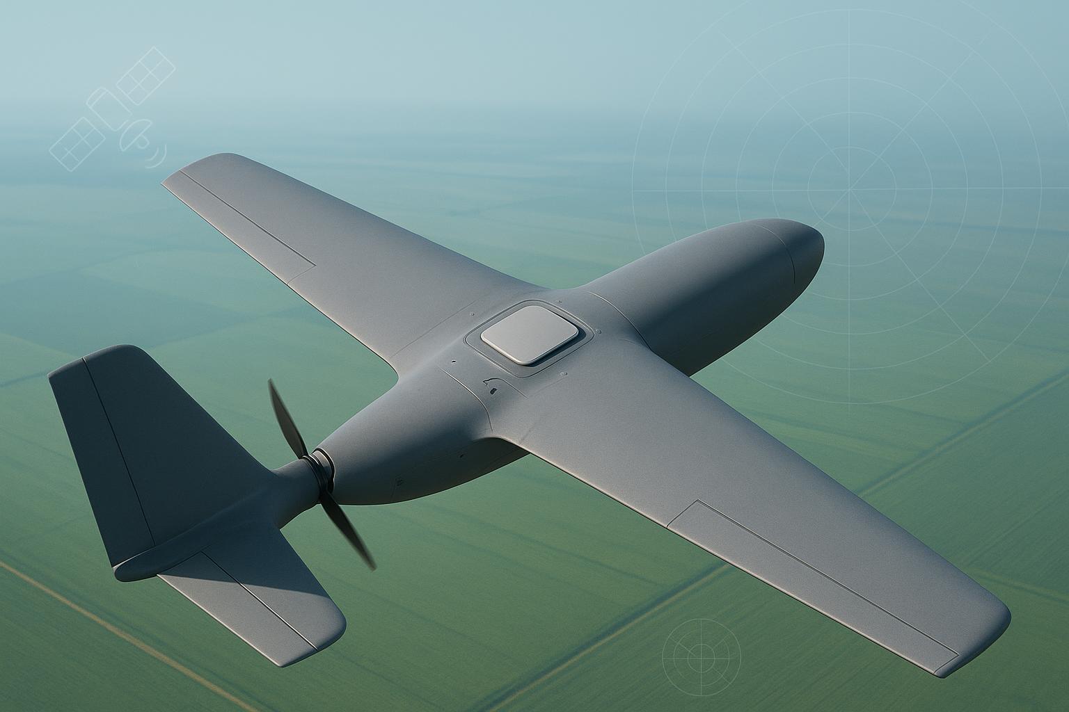
When a wildfire cut power and cell coverage across two valleys last summer, our mapping UAV still had to fly corridor inspections. The airframe carried its usual RTK GNSS stack plus a compact satellite short‑message terminal—an RDSS‑type link for emergency check‑ins and command updates. On paper, both systems were independent. In the field, the transmit bursts from the satellite terminal knocked just enough margin off the GNSS carrier tracking to delay RTK fixes on low‑elevation satellites. That day reminded me: getting emergency comms working is only half the job; keeping centimeter‑level navigation stable while it transmits is the other half.
This article distills what has worked for me integrating an RDSS‑class satellite antenna alongside RTK GNSS on small to medium UAVs: how to pick and place antennas, manage the RF chain, schedule transmissions, and—most important—how to prove coexistence with data. For the core RTK antenna decisions this builds on, see our UAV GNSS antenna selection & integration guide.
RDSS, GNSS, and the coupling you actually fight
Radiodetermination‑Satellite Service (RDSS) is defined by the ITU as radiocommunication used for radiodetermination with one or more space stations. In BeiDou’s ecosystem, public technical material shows short‑message RDSS operating at 2483.5–2500 MHz with strict interference‑power limits (−125 dBm/MHz in band) per a 2018 ICG/UNOOSA paper; those constraints underscore why clean coexistence matters near adjacent services. See the UNOOSA/ICG brief (“WGS 08,” 2018) for the published figures: BeiDou RDSS interference‑power limits and 2483.5–2500 MHz band.
GNSS for RTK ties together weak, spread‑spectrum signals across multiple bands (L1/L2/L5). What hurts you on a UAV isn’t usually in‑band jamming; it’s nearby high‑level out‑of‑band energy that drives the GNSS front‑end into a less linear region or raises the noise floor enough to cost you 2–4 dB‑Hz of C/N0 on several satellites at once. ESA’s Navipedia explains how interference translates into C/N0 deltas and loss of lock probability; it’s a handy mental model when you’re trading separation versus filtering: GNSS Interference Model (ESA Navipedia).
On aircraft, DO‑160 qualification and FAA/RTCA guidance frame the EMI/EMC discipline. For small UAS, measurement‑based patterns in the ASSURE A56 program (2021) highlight how distance, bonding, and filtering move the needle on susceptibility: ASSURE A56 UAS EMC study. For interference‑risk framing and cosite thinking, FAA AC 91.21‑1D references RTCA DO‑307/DO‑307A path‑loss concepts applicable to “strong emitter near sensitive receiver” scenarios: FAA AC 91.21‑1D on PED interference concepts.
Why RDSS antenna choices matter for RTK on a drone
Here’s the practical chain: an S‑band terminal transmits; energy couples via space and the airframe into the GNSS antenna and its coax; the GNSS front‑end exhibits a small C/N0 drop and, if timing is unlucky, a few cycle slips. A couple of slips during ambiguity resolution stretch time‑to‑fix; lower C/N0 on low‑elevation satellites can push you under the weighting threshold used by the RTK filter. The visible effects are:
-
Longer time‑to‑first‑fix or re‑fix after yaw/roll events.
-
Reduced fix ratio in dynamic segments when the terminal bursts near the RTK correction epochs.
-
Slightly higher horizontal residuals (H‑RMS) and occasional reversion to float.
I treat a per‑satellite C/N0 delta of ≤3 dB‑Hz during terminal activity as an initial pass/fail screen. Anything worse usually shows up in mission metrics unless you compensate elsewhere (added constellations, better antenna axial ratio, or strong filtering).
Field test: two mounts, TX off/on, and what actually changed
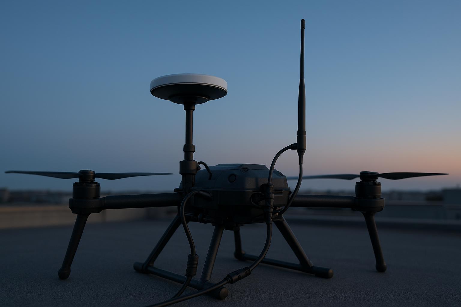
Platform: 6‑kg quadcopter, carbon composite top deck. GNSS: multi‑band RTK receiver with a circularly polarized low‑PCV antenna (L1/L2/L5). RDSS terminal: compact S‑band short‑message unit with a small monopole. We tested two GNSS antenna mounts and compared terminal OFF vs ON at nominal EIRP. Identical paths (three 600 m legs) and 60‑s hovers at 25 m AGL were flown back‑to‑back.
-
Mount A (roof center): GNSS on a 10‑cm mast at deck center; RDSS whip 12 cm aft and 6 cm below on a boom.
-
Mount B (raised and separated): GNSS on a 25‑cm mast with bonded ground ring; RDSS whip 30 cm below and 20 cm lateral on a carbon boom tip; added ferrite chokes at both cable entries.
Mitigations applied on B: improved bonding to a defined RF ground, common‑mode chokes on both RF cables and RDSS power, transmission scheduling to avoid RTK correction epochs by ±200 ms.
Key results (median across three flights):
KPI | Mount A, TX OFF | Mount A, TX ON | Mount B, TX OFF | Mount B, TX ON |
|---|---|---|---|---|
Avg C/N0 drop vs OFF (per‑sat) | — | 2.8 dB‑Hz | — | 0.9 dB‑Hz |
Time‑to‑fix after hover yaw | 9.5 s | 14.1 s | 8.8 s | 10.2 s |
Fix ratio during legs | 97.8% | 92.6% | 98.3% | 97.1% |
Horizontal RMS residual | 1.8 cm | 2.7 cm | 1.7 cm | 2.1 cm |
RDSS packet error rate | — | 1.8% | — | 1.4% |
Interpretation: With poor separation and bonding (Mount A), TX reduced GNSS margin enough to increase time‑to‑fix by ~48% and cut fix ratio by ~5 points. Raising the GNSS antenna, adding separation and chokes (Mount B) trimmed the C/N0 hit to ~1 dB‑Hz and kept fix ratio above 97% while maintaining RDSS link quality. Think of separation as your first lever; filtering and bonding decide whether you need a full redesign.
A useful co‑site data point from a different service: UNAVCO documented severe GPS degradation from nearby Iridium transmitters without filtering, yet achieved excellent GPS data with a >20 dB notch filter and only ~30 m separation—better than 100 m with distance alone. The lesson stands: smart filtering can beat brute‑force spacing when bands are near sensitive front‑ends: UNAVCO cavity‑type notch filter case.
RDSS antenna considerations for drones: what to pick and where to put it
-
Polarization and pattern: Many satellite user terminals favor circular polarization and wide sky coverage. Verify against your terminal’s datasheet; don’t assume. Favor antennas with stable gain across low elevations to minimize body masking during banked turns.
-
Separation and placement: On multirotors, vertical separation of 0.3–0.5 m between RDSS and GNSS antennas is a good starting point; more if EIRP or duty cycle is high. Keep the RDSS radiator away from GNSS ground planes and carbon spars that can act as coupling antennas.
-
RF chain hygiene: Keep coax short and low‑loss. For example, LMR‑200‑UF is about 15.5 dB/100 ft at ~1.5 GHz (≈0.51 dB/m) and 20.2 dB/100 ft at ~2.5 GHz (≈0.66 dB/m) per an L‑com datasheet: LMR‑200‑UF attenuation table (L‑com PDF). Account for connectors and any in‑line filters.
-
Filtering strategy: If your RDSS band sits near sensitive GNSS front‑end regions or harmonics, add preselection or a notch in the earliest possible place (in‑antenna or immediately after). Measurement‑based EMI notes back this approach for GNSS susceptibility management: Measurement‑based interference mitigation overview.
Common engineering mistakes I still see
-
Mounting the RDSS whip inches from the GNSS puck “to keep cables short,” then wondering why C/N0 dips 3–4 dB‑Hz during bursts.
-
Carbon decks without intentional bonding, creating floating grounds and generous common‑mode paths.
-
Long runs of thin coax to convenient avionics bays; insertion loss silently erodes link budgets and SNR margins.
-
Firmware that transmits at fixed intervals aligned with GNSS/RTK epochs, maximizing the chance of cycle slips.
-
Relying on a single hover test; dynamic legs often reveal the real coexistence problems.
A practical improvement checklist for your next install
-
Target ≥0.3–0.5 m vertical separation between GNSS and RDSS antennas; increase if TX duty/EIRP is high.
-
Bond GNSS ground to a defined RF reference; add common‑mode chokes to both RF coaxes and the RDSS power lead.
-
Keep coax short; choose low‑loss cable (e.g., LMR‑200/240). Budget connector and filter loss; re‑measure after routing.
-
If C/N0 drops >3 dB‑Hz with TX, add preselection/notch filtering near the GNSS antenna and improve shielding paths.
-
Stagger RDSS transmissions away from RTK correction epochs by a few hundred milliseconds; limit duty cycle.
-
Validate with matched TX OFF/ON flights; enforce pass criteria: ≤3 dB‑Hz C/N0 drop, ≤30% fix‑time increase, ≥95% fix ratio.
A neutral workflow example with GNSource hardware practice
On a recent forestry survey airframe, I used a multi‑band RTK antenna with tight PCV control mounted on a 20‑cm mast and a small S‑band terminal on a lateral boom 25 cm below. Commissioning started with a TX‑OFF baseline: I logged raw observations, built a CN0‑by‑elevation plot, and verified low cycle‑slip rates in gentle yaw maneuvers. Next, with TX‑ON at nominal power, the initial C/N0 hit averaged 2.4 dB‑Hz on low‑elevation satellites and pushed time‑to‑fix after hover to ~13 s.
Two changes solved it: a pair of ferrite chokes at the GNSS cable entry and moving the GNSS antenna up another 5 cm on a bonded ring. The C/N0 delta dropped to ~1.1 dB‑Hz, and time‑to‑fix returned to ~9–10 s. If you need a concise primer on placement, ground‑plane use, PCV models, and validation steps, the guidance in RTK antenna mounting and calibration from GNSource aligns with what we executed here. I treat that page as a checklist for mast rigidity, ground‑plane sizing, short low‑loss cabling, and commissioning logs before enabling any non‑GNSS transmitters. Use it as a cross‑reference while you collect your own CN0 and fix‑ratio baselines.
Note: I’m mentioning GNSource purely as a practical reference for mounting/calibration practice; any multi‑band, low‑PCV RTK antenna with solid vendor pattern files and a documented PCV model will serve.
Short FAQ
What polarization should I use for the RDSS terminal?
Check the terminal’s datasheet and vendor guidance. Many satellite links use circular polarization, but design choices vary. Don’t assume—verify and test link quality across attitude changes.
How much separation is “enough” between GNSS and RDSS antennas?
Start with 0.3–0.5 m vertically on multirotors and validate. If your measured C/N0 drop exceeds ~3 dB‑Hz with TX, add distance, filtering, or both.
Can filtering replace physical separation?
Targeted preselection or a notch close to the GNSS front‑end can dramatically improve coexistence, sometimes allowing reduced spacing. The UNAVCO Iridium example shows filtering outperforming distance alone.
Do I need to change firmware timing?
If your terminal allows it, avoid transmit bursts aligned with GNSS/RTK epochs; staggering by a few hundred milliseconds reduces cycle‑slip risk during ambiguity resolution.
How should I budget coax loss on a small UAV?
Use manufacturer tables. As a reference point, LMR‑200‑UF is roughly 0.51 dB/m at ~1.5 GHz and ~0.66 dB/m at ~2.5 GHz (L‑com). Keep runs short and include connector/filter loss.
If you want a single reference to sanity‑check mounting and calibration steps, the GNSource guide above is a solid place to start for RTK‑focused installs.