GNSS antenna integration starts with the platform, receiver and measurement task. A survey UAV, an agricultural vehicle, a hydrographic vessel and a fixed monitoring station can use similar satellite signals while needing different mounting, RF-chain and environmental arrangements.
The useful procurement question is which configuration can be evaluated in your equipment. An application label on a catalogue page does not establish receiver compatibility, achieved positioning accuracy or qualification for a particular platform.
This guide helps device designers and technical buyers turn civil platform requirements into a supplier brief. It covers installation decisions for positioning and measurement equipment; approval of a complete navigation or control system requires its own engineering process.
GNSS antenna integration: define the platform first
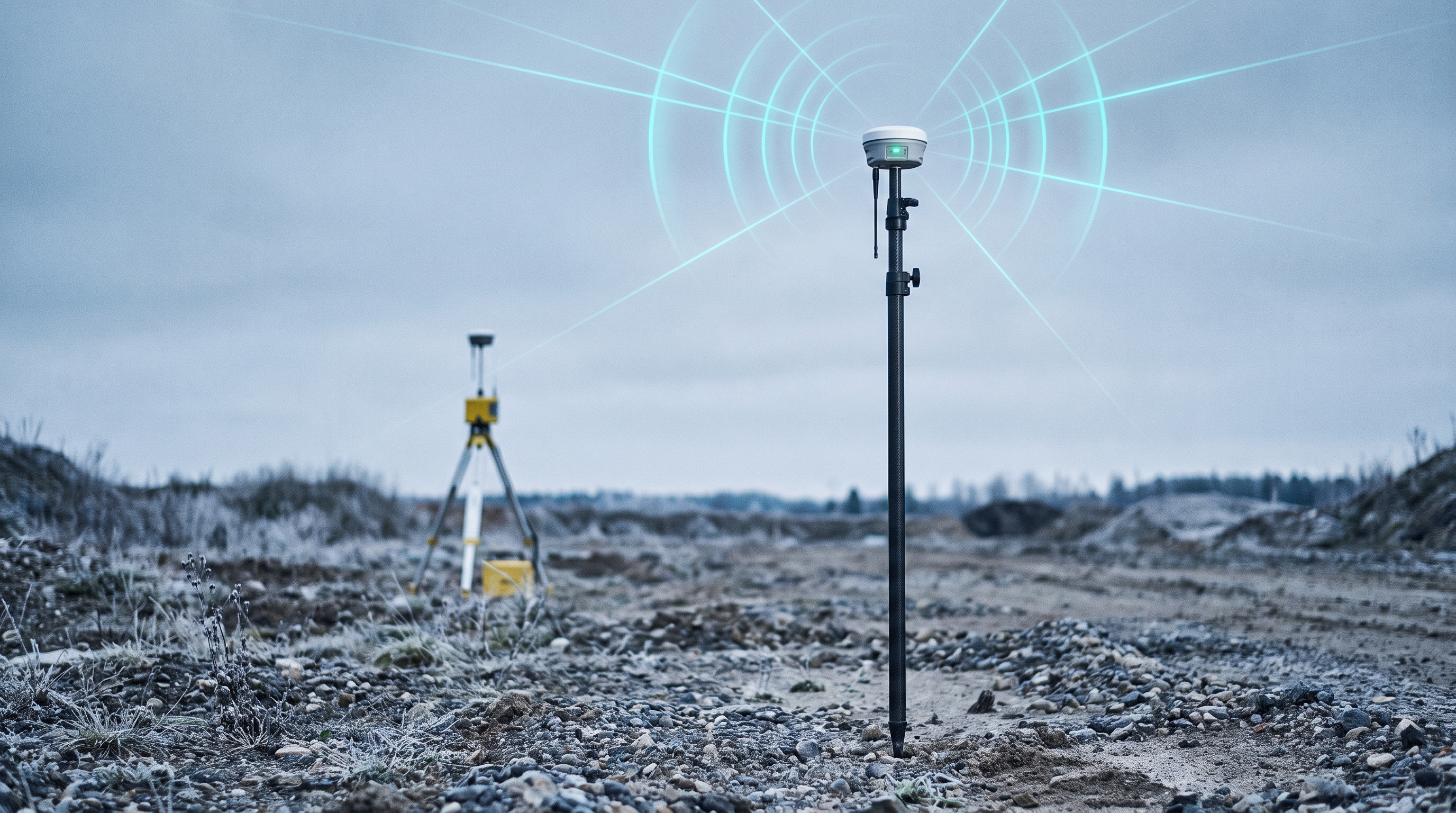
Start with the output your project needs. Is the antenna supporting a survey observation, a moving vehicle position, a heading baseline or a fixed time reference? These are different acceptance tasks, even when the RF connector and supported bands look similar.
| Platform | Installation constraint to investigate | Evidence to request |
|---|---|---|
| Civil survey UAV | Mass, mounting space, changing attitude and onboard electronics | Antenna dimensions and mass, intended mounting arrangement, RF data and installed-system logs |
| Agricultural or industrial vehicle | Roof geometry, nearby structures, vibration and cable routing | Mounting drawing, ground-plane guidance, cable assembly and relevant environmental reports |
| Hydrographic or survey vessel | Mast location, nearby transmitters, moisture and installation geometry | Sealing configuration, material information, mounting details and co-site RF evaluation |
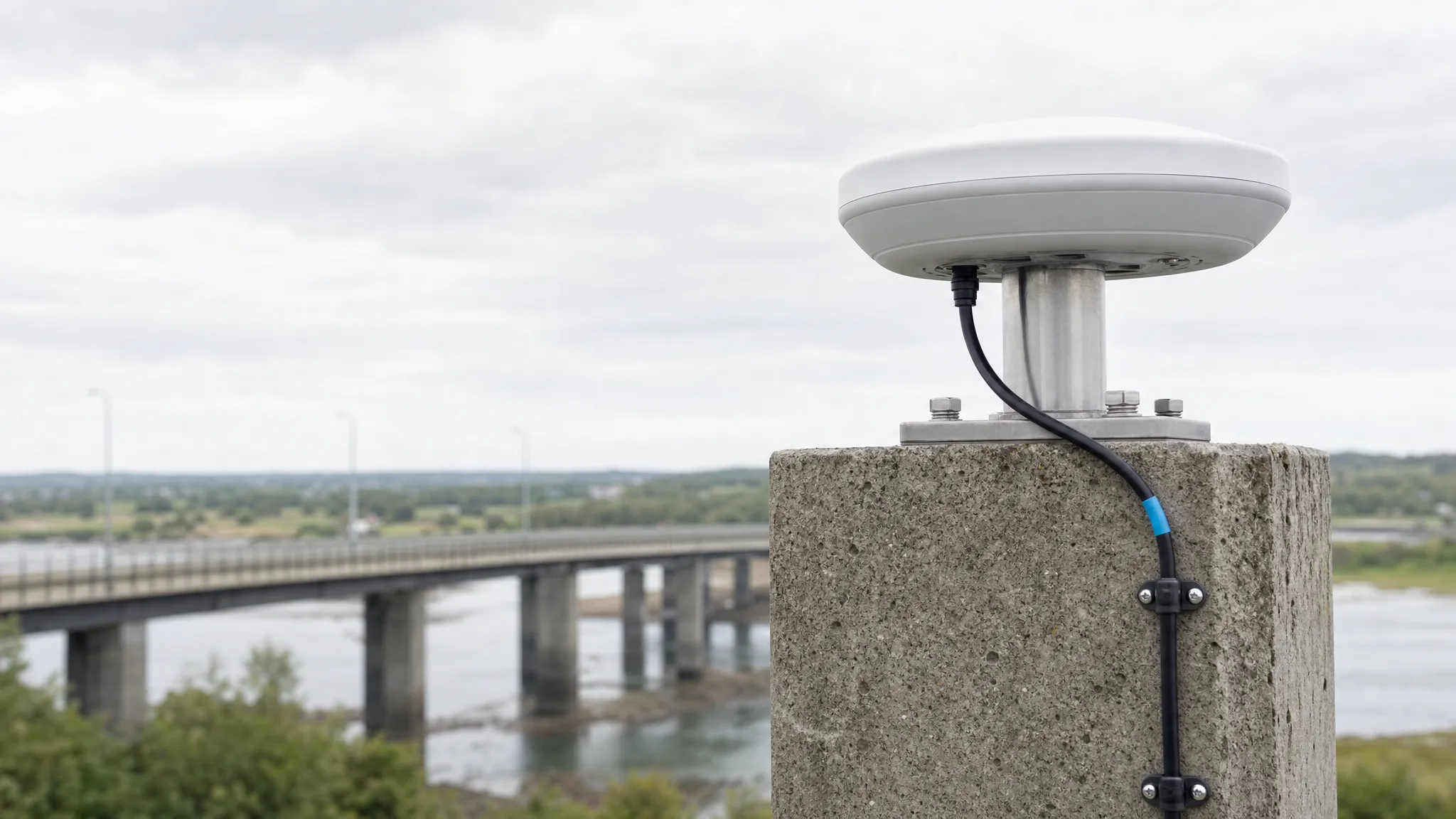
| Fixed monitoring or reference site | Stable reference point, long-term mounting and processing model | Antenna/radome identification, reference drawing, applicable calibration and maintenance requirements |
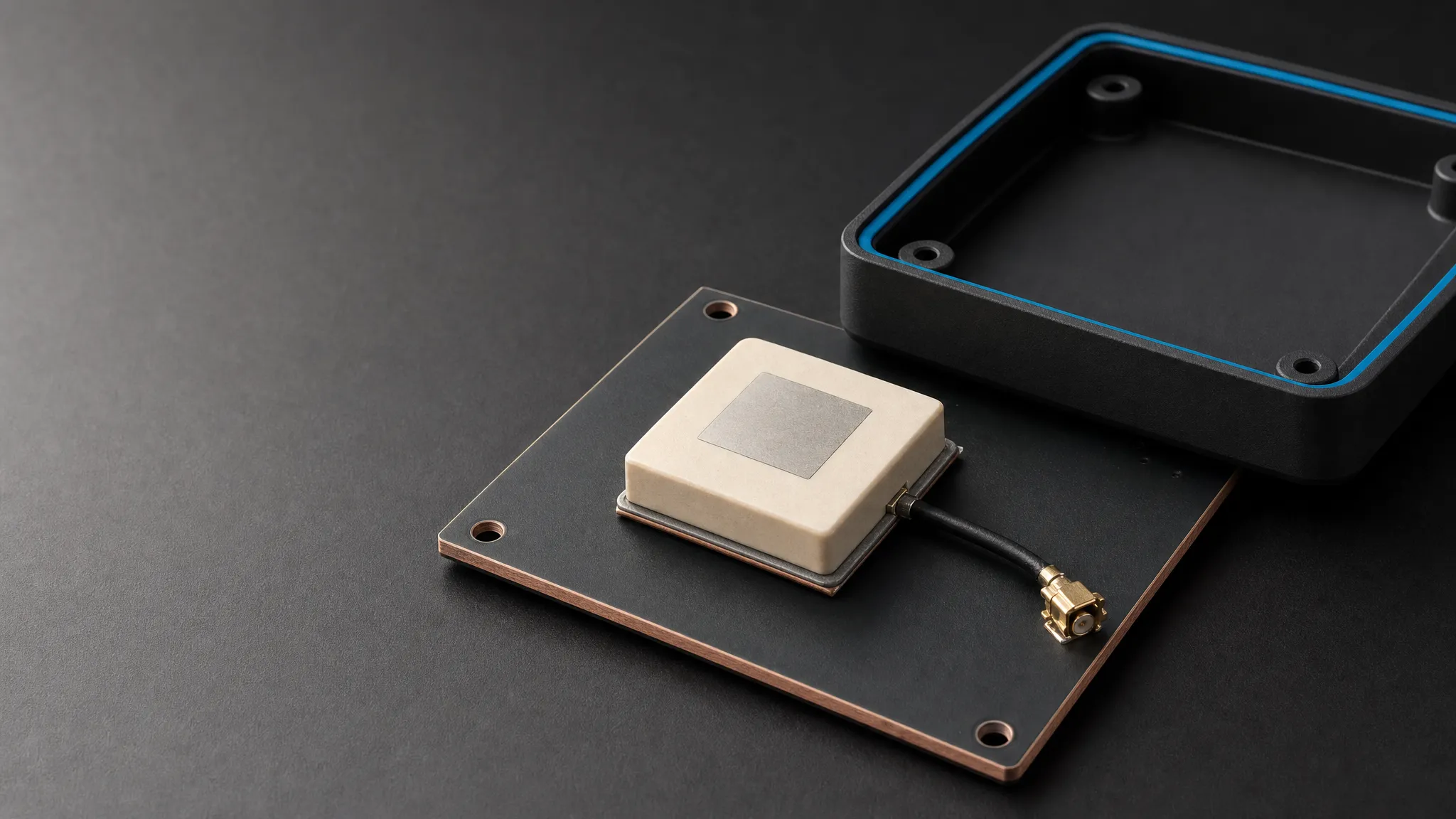
The table identifies review tasks, not a universal ranking of antenna types. A low-profile patch, a helical assembly and a larger survey antenna each need to be assessed in their intended configuration. Do not assume that a product’s shape alone establishes its amplification architecture or measurement quality.
Match the receiver and the RF path
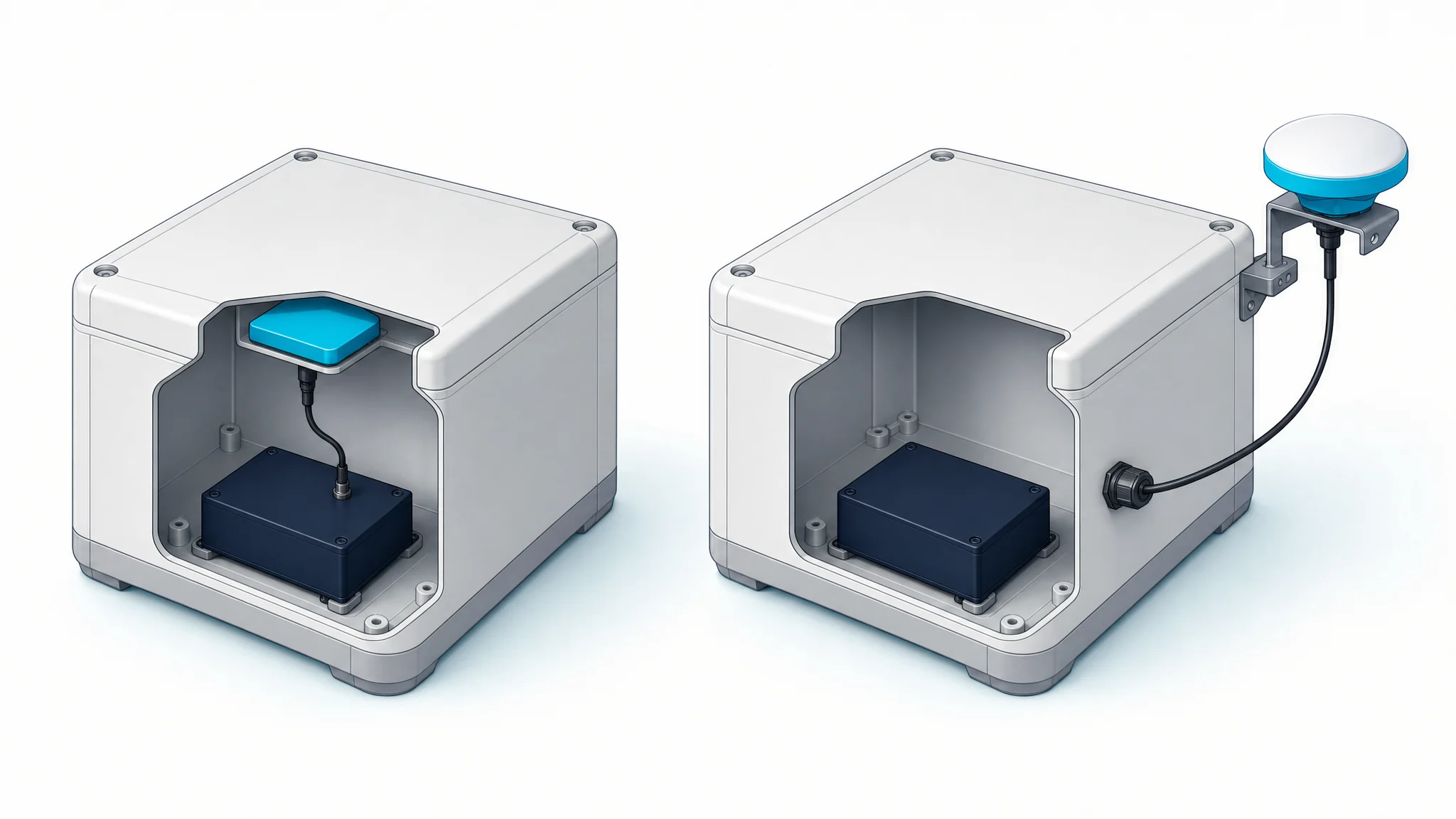
Identify the receiver model, hardware revision, configuration and actual signals to be used. Then list the path from the antenna to the receiver input, including cable, adapters, splitters, protection and any additional amplification.
For an active antenna, verify its supply range, current requirement and the receiver’s antenna-bias capability. Check the entire DC path as well as the RF path: an inline component may pass the satellite signals while blocking the antenna’s supply. A passive antenna also needs a receiver front end designed for that arrangement.
The u-blox GNSS antennas application note, R03 (2019) provides useful background on antenna placement, active/passive arrangements and interference. Its reference designs and electrical limits must be interpreted for the documented receiver rather than applied to every product.
Document cable loss at the required frequencies and the location of the first low-noise amplifier. Compare the complete electronic gain budget with the receiver’s permitted range. Higher gain is not a substitute for a compatible supply, low noise or appropriate installation.
For a mixed positioning-and-communications system, identify which assembly receives satellite RF, which component processes position, and which radio transmits. A receive antenna does not provide a communications service simply because it supports BeiDou or another navigation constellation.
Civil UAVs: evaluate the complete installed assembly
On a small airframe, the antenna shares limited space with structural material, wiring, power electronics and radios. Review its mounting surface and orientation together with the available sky view. Account for the housing, support, connector and cable when checking mass and clearance.
Use the antenna manufacturer’s intended ground-plane arrangement as the starting point. There is no single plate size, standoff height or separation distance that establishes performance for every antenna and airframe. A change to a nearby structure can also change the installed result.
Define a staged evaluation. First verify the RF and power arrangement with the equipment secured. Then compare receiver observations with relevant subsystems enabled under controlled conditions. Flight evaluation belongs in the platform’s approved test process, with acceptance criteria chosen for the surveying application.
The UAV vibration, shock and temperature checklist explains how to request environmental evidence for the actual mounted configuration. A test report on an antenna component does not by itself approve the entire aircraft installation.
Vehicles: keep the antenna reference and mounting geometry clear
Vehicle installations add roof structures, moving equipment and changing surroundings. A location that has open sky on an unfinished prototype may be obstructed after cameras, warning lights, a roof rack or an implement are installed. Review the production layout rather than evaluating the bare vehicle only.
Document the antenna reference point and its relationship to the vehicle’s coordinate frame. Where a receiver combines GNSS with an inertial sensor, the relevant offsets and sign conventions must come from that system’s documentation. An antenna supplier cannot determine them from the RF connector.
For GNSS heading, treat the antenna baseline as part of the mechanical design. Record both antenna models, orientations, mounting surfaces and reference points. Baseline requirements and resulting heading performance depend on the selected receiver and installation; there is no universal spacing that guarantees a particular heading accuracy.
Keep functional positioning tests separate from claims about autonomous-system safety. A fixed RTK solution is an observation from a positioning engine, not an independent certificate of position integrity. The vehicle accuracy and integrity guide explains that system boundary.
Vessels: review moisture, geometry and nearby radios together
For a civil survey vessel, the proposed mast location must work mechanically and electrically. Check sky obstruction, reflections from nearby structures, the movement of the support and the other equipment sharing the installation.
Request the sealing conditions for the complete assembly, including the connector and cable exit. A housing ingress rating does not establish resistance to every cleaning method, long-term corrosion or a service life measured in years. Those require separate evidence and maintenance planning.
Nearby transmitters deserve a co-site review. List their frequencies, operating modes and antenna locations, then have the RF design assessed against the GNSS front end’s documented limits. Filtering or protection should be selected from that assessment; it is not an automatic promise of uninterrupted reception.
For hydrographic measurement, also document how the antenna position relates to the vessel sensors and the survey processing frame. Antenna selection cannot replace time alignment, lever-arm measurement or calibration of the complete survey system. The civil marine GNSS installation guide develops these requirements further.
Fixed sites: preserve the reference configuration
A permanent reference or deformation-monitoring site needs a repeatable physical configuration. Record the antenna reference point, mounting orientation, cable assembly and any radome. Plan how maintenance or replacement will be recorded so that a hardware change is not mistaken for movement of the monitored object.
Where the processing workflow uses antenna phase-center corrections, obtain the model that matches the actual antenna and radome. NGS antenna calibration information identifies calibrations by that combination and explains the need to keep calibration products consistent with the processing reference frame. A generic accuracy phrase on a datasheet is not the same evidence.
Choose an environmental test plan for the actual site and mounting. Ask which sample configuration was tested, the method and exposure conditions, and the electrical or mechanical checks performed afterwards. The antenna environmental qualification guide provides a report-review framework.
Turn platform requirements into a comparable quotation
Send each supplier the same baseline information. Otherwise, two prices can refer to different cables, interfaces, mounting parts or levels of verification.
| RFQ input | Detail that prevents a mismatched proposal |
|---|---|
| Receiver and signals | Exact receiver, required signal list and relevant configuration |
| RF and power | Active/passive arrangement, bias supply, permitted input gain and inline equipment |
| Mechanical installation | Available envelope, orientation, mounting surface, reference point and cable route |
| Operating environment | Measured or specified temperature, moisture, vibration and exposure conditions |
| Required evidence | Drawings, RF measurements, model-specific reports and calibration where applicable |
| Acceptance and supply | Evaluation criteria, sample quantity, production quantity and configuration control |
GNSource’s antenna selector and project brief can help collect these inputs for an engineering enquiry. Use the resulting brief to request a candidate configuration and supporting documents, then agree how the installed sample will be evaluated before committing to production.
Frequently asked questions
Can the same GNSS antenna be used on a UAV and a vehicle?
Possibly, if the receiver, signals, RF chain, mounting and environment are compatible. Shared satellite bands do not establish that the installed configurations will perform alike. Evaluate each platform separately.
Does a rugged antenna guarantee high-precision positioning?
No. Environmental endurance and positioning performance are different requirements. The receiver, signals, corrections, antenna characteristics and installation all contribute to the measurement result.
Does a published antenna calibration certify the whole system?
No. A calibration describes a particular antenna configuration for a specified measurement or processing use. It does not validate the receiver setup, vehicle geometry, installation, control system or operating procedure.
What should I send when I only have a receiver model?
Start with that model, the required application, signal list, mounting space and proposed cable. Obtain the receiver’s RF and antenna-power requirements, then request a candidate and sample-evaluation plan. Do not fill missing requirements with assumed gain or voltage values.