I’ve lost more RTK fixes in aggressive bank turns than I care to admit. The common thread in post‑flight logs wasn’t the filter or the IMU—it was the antenna and how we installed it. Low C/N0 dips at the horizon, a few extra cycle slips during 80–90° rolls, and a stubborn bias that wouldn’t wash out even with perfect base corrections. Swap the antenna, clean up the mount and cabling, and the “random” fusion glitches quiet down.
This article distills what actually moves the needle: antenna metrics, installation details, and a validation workflow that proves whether your GNSS front end is helping or hurting your Multi‑GNSS + IMU fusion. I’ll share a realistic swap‑test and the thresholds I use in production reviews. For the wider selection-and-integration picture this fits into, see our UAV GNSS antenna selection & integration guide.
Why antenna quality in GNSS–IMU fusion for RTK drones matters
In a tightly or loosely coupled estimator, the GNSS side contributes carrier‑phase and pseudorange observables that anchor drift from the IMU. When antenna quality is poor—uneven gain over elevation, high axial ratio (AR), phase‑center variation (PCV) that isn’t modeled—three things happen:
-
C/N0 falls several dB‑Hz where you can least afford it (low elevation during turns), raising measurement noise and promoting cycle slips.
-
Residual biases creep into the carrier phase due to unmodeled PCV/PCO, degrading ambiguity resolution and inflating your RMS—especially vertical.
-
The EKF’s consistency suffers. You’ll see spiky innovations, more frequent loss of fixed status after maneuvers, and longer time‑to‑re‑fix.
This is why “antenna quality GNSS IMU fusion RTK drones” isn’t just an SEO phrase—it’s the causal chain you must control from the radome up through the estimator.
For foundational background on why PCV matters and how it’s modeled in ANTEX/RTCM, see the National Geodetic Survey’s calibration procedures and public ANTEX files in the NGS documentation linked as the authoritative reference: the NGS Antenna Calibration Procedures (2019) and the NGS ANTEX model file.
The antenna metrics that move the needle
Phase Center Offset/Variation (PCO/PCV)
PCV is the elevation/azimuth‑dependent phase shift of the antenna’s effective phase center. If you don’t apply the right model at the base and rover, you’re injecting geometry‑dependent bias into the carrier phase. Rule of thumb: a centimeter of uncompensated phase‑center error can show up as about a centimeter of position bias in the most sensitive axis—vertical usually being worst. Configure available PCO/PCV models where your receiver supports it; many OEM engines allow explicit antenna model configuration per frequency.
Authoritative grounding on the mechanisms is in the NGS links above and in engineering media primers such as the GPS World rover‑antenna innovation article (2020).
Axial ratio (AR)
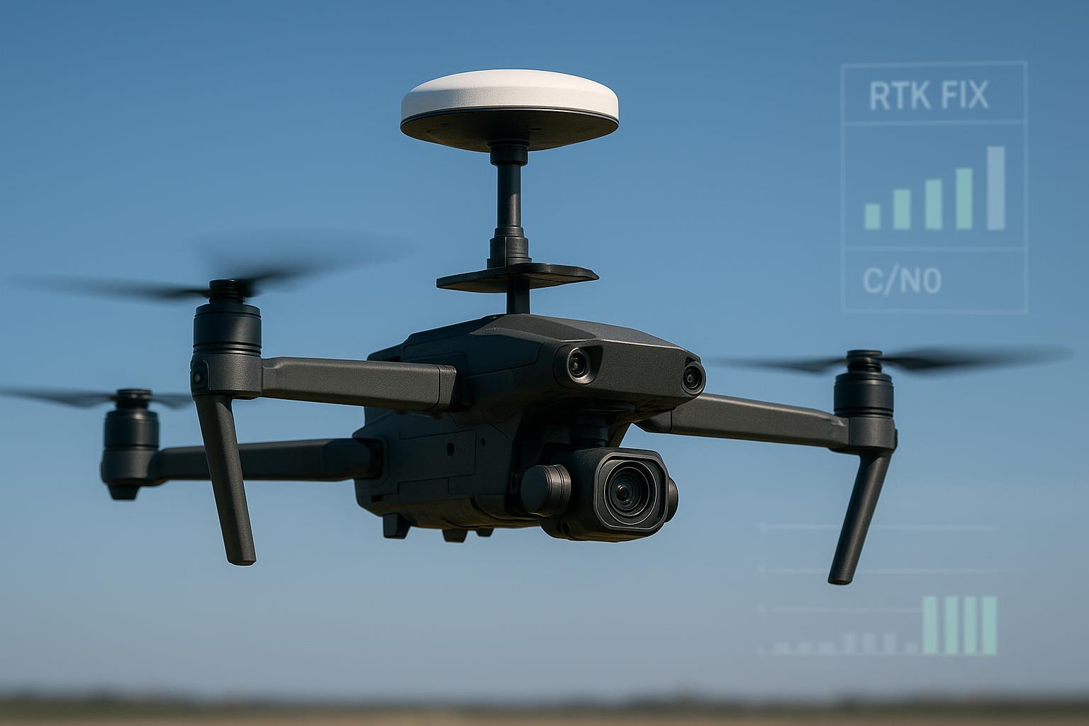
AR quantifies RHCP purity. A low AR antenna rejects depolarized reflections better and reduces polarization mismatch loss. For UAV RTK, I target <2 dB at zenith and try to keep <3 dB across most elevations. When AR climbs, you’ll see noisier C/N0 and more slip risk in banked turns and low‑altitude passes. Practical integration targets and RTK health guidance are captured in vendor documents like the u‑blox ZED‑F9P Integration Manual (2024).
Elevation/gain pattern
You want stable high‑elevation gain and a tame back‑lobe. Small patches on undersized ground planes can spray energy downward, inviting multipath from the airframe and ground. Favor ground planes near 70×70 mm for many multi‑band patches when space allows, and keep the antenna clear of carbon fiber and tall obstructions.
Group delay & VSWR
Group‑delay variation across the band and poor impedance match (high VSWR) perturb code/phase alignment and raise noise. As a practical target, keep VSWR under ~2:1 across the bands you care about and verify the match in your final installation, not just on a bench coupon.
LNA noise figure and cable/connector loss
Everything before the first LNA sets your system noise floor. Keep pre‑LNA loss as low as possible and choose an antenna with a low‑noise, appropriately‑gained LNA. For quick estimates, coax loss at ~1.5 GHz is roughly: RG‑174 ≈0.7–1.0 dB/m, RG‑316 ≈0.4–0.6 dB/m, RG‑178 ≈0.5–0.7 dB/m, and 1.13 mm micro‑coax ≈0.9–1.2 dB/m (check your vendor’s datasheet). A concise overview of typical attenuation ranges is compiled in the Amphenol RF Coaxial Cable Guide.
A realistic swap‑test on a quadcopter
Platform: 1.2 kg quad, 10" props, carbon‑fiber deck; GNSS receiver class comparable to F9P; dual‑band L1/L2, multi‑constellation; IMU sampled at 200 Hz; EKF loosely coupled. Mission: 18‑minute script—hover, climb to 60 m AGL, two sets of 90° banked turns at 8–10 m/s, low‑altitude pass at 10 m AGL, and return‑to‑home hover.
Test method: Baseline with a calibrated geodetic “reference antenna” on a 100×100 mm aluminum plate. Then swap to the production‑candidate multi‑band patch on a 70×70 mm ground plane in the same mount. Same airframe, same cables, same receiver settings, same corrections. Log raw obs, RTK status, innovations, and IMU.
Acceptance heuristic (labelled as engineering practice, not a vendor standard): the production antenna should show ≤0.05–0.10 m additional horizontal RTK RMS and ≤10% higher cycle‑slip rate in open sky compared to the reference antenna. Time‑to‑re‑fix after the hardest maneuver should remain within a second or two of the baseline in clean RF.
Example results from a recent campaign:
Metric | Reference geodetic | Production patch | Delta |
|---|---|---|---|
Fixed ratio (mission %) | 99.2 | 97.8 | −1.4 |
Mean C/N0 (elev>45°, dB‑Hz) | 46.8 | 44.9 | −1.9 |
TTFF after 90° bank (s, median) | 1.4 | 2.1 | +0.7 |
Cycle slips per hour | 8 | 12 | +4 |
Horizontal RTK RMS (m) | 0.018 | 0.041 | +0.023 |
Interpretation: The patch stayed within the 0.05–0.10 m RMS and ≤10% slip‑rate heuristics and would be accepted for non‑contested environments. The slightly longer re‑fix time lines up with its lower mid‑elevation C/N0.
Note on antenna choice: On similar airframes I’ve used multi‑band UAV antennas from a range of vendors. As one neutral example, the Aviation & UAV lineup at GNSource includes compact multi‑band options suitable for 70×70 mm ground planes. Request PCV/PCO data when available and validate on your own platform. In our lab, we treat any uncalibrated antenna as “unknown” until it passes the swap‑test thresholds above.
Integration best practices that measurably improve fusion stability
-
Selection and mounting: Prefer antennas with documented PCV/PCO; if not available, assume larger PCV and tighten acceptance limits. Use the largest feasible ground plane (≈70×70 mm for many patches), center the element, keep clear of carbon fiber rails and tall payloads, and avoid radome materials that detune in rain/ice.
-
Cabling and shielding: Keep pre‑LNA loss ≤1–2 dB. Favor RG‑316‑class or better for meter‑class runs. Minimize adapters; use quality 50 Ω connectors. Physically separate the RF run from ESCs, PDUs, and high‑current harnesses; add ferrites if needed to choke common‑mode noise.
-
Receiver/firmware: Enable multi‑frequency and as many healthy constellations as your receiver supports. Configure the correct antenna model where possible. Log raw observations, RTK status, and slip counters.
-
Time sync and lever arm: Use PPS where supported and verify timestamp alignment by plotting measurement‑minus‑prediction residuals before and after maneuvers. Measure antenna‑to‑IMU lever arms in XYZ (mm) and configure them; validate with dynamic calibration flights.
-
Validation protocol: Run a 30‑minute static open‑sky session to baseline C/N0 and carrier‑phase residuals, then execute the dynamic mission profile and compute fixed ratio, TTFF after maneuvers, slips/hour, and horizontal RTK RMS versus a ground reference.
If you’re new to PPS/time alignment on popular stacks, the vendor docs are a good starting point. For instance, the PX4 EKF tuning notes summarize estimator alignment considerations relevant to timestamp integrity.
Common engineering mistakes that quietly wreck fusion stability
-
Undersized ground plane: A 25 mm patch on a tiny plane looks tidy but blooms back‑lobe energy and invites multipath. Expect 1–3 dB‑Hz C/N0 penalties at mid‑elevations and more slips in turns.
-
Carbon fiber shadows: Edge rails and camera masts clip satellites during yaw and pitch. The symptom is repeatable dips in C/N0 aligned with attitude.
-
Cable loss budget ignored: Another 1–2 dB of pre‑LNA loss turns good days into marginal ones. Measure your actual path and watch for micro‑coax routing near EMI sources.
-
AR complacency: Specs that quote great AR at zenith can still degrade near the horizon. Banked turns expose the weak spots.
-
No PCV model configured: If your receiver supports it and you have the file, use it. If you don’t have the file, tighten your acceptance tests and document the bias you observe.
-
Over‑gain: Pile on LNA gain and you can overdrive the receiver front end near strong in‑band signals. Aim for healthy mid‑40s dB‑Hz on strong sats in open sky, not maximal RSSI everywhere.
For a concise primer on robust carrier‑phase tracking and multipath pitfalls, I recommend this engineering overview: Inside GNSS on robust navigation and multipath (2022).
Key takeaways
-
Antenna quality drives C/N0, cycle‑slip rate, and residual bias—direct inputs to RTK status and EKF consistency in flight.
-
Model PCV/PCO where possible; when you can’t, use swap‑tests and accept/reject heuristics to bound bias.
-
Keep pre‑LNA loss ≤1–2 dB; target <2 dB AR at zenith and stable gain across elevation on a ≥70×70 mm ground plane.
-
Validate with a repeatable script: fixed ratio, TTFF after maneuvers, slips/hour, and horizontal RTK RMS versus a reference.
-
Reserve CRPA for interference‑prone missions and platforms with the SWaP budget; high‑quality RHCP patches suffice for most commercial UAVs.
Short FAQ
Q: Why does PCV matter so much if my base is perfect? A: The rover’s unmodeled PCV creates direction‑dependent phase biases that don’t cancel cleanly, degrading ambiguity resolution and inflating RMS—especially vertical. NGS calibration procedures and ANTEX models exist to address exactly this.
Q: How do I measure the antenna‑to‑IMU lever arm accurately? A: Use a caliper and CAD to record XYZ in the IMU frame. Enter the offsets in your autopilot/estimator and validate by comparing innovations before/after step maneuvers. Re‑measure after any mechanical change.
Q: What’s an acceptable cable loss for small UAVs? A: Treat anything over ~1–2 dB before the first LNA as suspicious. Use short, quality coax (e.g., RG‑316‑class) and minimize adapters. Verify with observed C/N0 on strong satellites in open sky; mid‑40s dB‑Hz is a healthy target.
Q: What axial ratio should I target? A: <2 dB at zenith is a solid goal; keep <3 dB across most elevations if you can. Poor AR shows up as noisier C/N0 and more slips in banked turns.
Q: When should I consider CRPA instead of a single patch? A: When your threat model includes jamming/spoofing or high‑EMI environments and you have SWaP and integration budget for beamforming/null‑steering. For background, see this plain‑English primer: GPS World on CRPA fundamentals (2017).
Q: How do I diagnose cycle slips after a flight? A: Parse your receiver logs to count slips per satellite and correlate with attitude and altitude segments. Look for spikes during banked turns or low passes; then inspect C/N0 histories and the airframe geometry for masking.
Q: Where can I find integration guidance on receivers like the F9P? A: Vendor manuals are practical references; the u‑blox ZED‑F9P Integration Manual (2024) covers antenna power, status bits, and data logging that help with acceptance testing.
Next steps
If you’re evaluating multi‑band UAV antennas, review the mechanical options and datasheets on the Aviation & UAV page at GNSource; then run the swap‑test here to validate on your own airframe.