If you’ve ever watched an otherwise solid UAV lose RTK lock mid‑mission or wait a minute for a first fix while the crew stares at the sky, you already know the pain. In my first season integrating RTK on carbon‑fiber airframes, our mapping quad needed 45–60 seconds to fix and dropped to float near buildings. The “receiver” wasn’t the whole problem—the integration of the UAV GNSS antenna was. Once we corrected siting, ground plane, and cabling, time‑to‑fix dropped to ~10–15 seconds and fix‑hold survived aggressive turns. This guide distills those lessons so you can build it right the first time.
Everything in the UAV GNSS antenna library
This guide is the hub. Below it sits the full library — branch left to choose the antenna, right to mount, harden, and qualify it. Each article links back here.
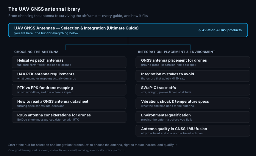
Choosing the antenna
- Helical vs patch GNSS antennas — the core form-factor choice for drones
- UAV RTK antenna requirements — what centimeter mapping actually demands
- RTK vs PPK for drone mapping — which workflow, and the antenna impact
- How to read a GNSS antenna datasheet — turning spec sheets into decisions
- RDSS antenna considerations for drones — BeiDou short-message coexistence with RTK
Integration, placement & environment
- GNSS antenna placement for drones — ground plane, separation, and the best spot
- Integration mistakes to avoid — the errors that quietly kill fix rate
- SWaP-C trade-offs — size, weight, power, and cost at altitude
- Vibration, shock & temperature specs — what the airframe does to the antenna
- GNSS antenna environmental qualification — proving the antenna before you fly it
- Antenna quality in GNSS-IMU fusion — why the front end shapes the fused solution
When you’re ready to spec hardware, the aviation & UAV antenna line is built for small, moving platforms.
Key concepts that actually move the needle
The fastest way to separate theory from results is to focus on the elements that change C/N0 and ambiguity resolution in practice.
-
Bands and constellations. Dual‑ or triple‑frequency (L1/L2 or L1/L2/L5) antennas let the receiver cancel ionospheric delay and resolve ambiguities faster; multi‑constellation improves geometry and satellite availability. For a concise primer, see Point One’s overview of how multi‑band receivers accelerate convergence and improve robustness in RTK contexts in their engineering explainer, the GNSS receivers and correction services summary (2025). For deeper vendor‑agnostic background on L1/L5 tradeoffs, Swift Navigation compares frequency combinations in L1/L2 vs. L1/L5 for high‑precision applications.
-
Active antenna, LNA, and filtering. Your antenna’s built‑in LNA has gain and a noise figure that must overcome cable and connector losses while rejecting out‑of‑band energy from onboard transmitters. Treat it as the first link in your signal‑to‑noise budget.
-
Phase center and ground plane. A stable phase center and an adequate ground plane reduce multipath and pattern distortion. On composite airframes, a dedicated metal or copper‑clad PCB plane is mandatory; don’t rely on carbon fiber for RF ground. Vendors routinely characterize compact L1/L2/L5 patches on 70×70 mm plates; ≥100×100 mm improves low‑elevation tracking, and a ≈150 mm disc can materially boost multipath rejection when space allows. See an example build log showing a 150 mm PCB ground plane behaving comparably to metal in a practical setup in this PCBWay measurement project.
-
Signal quality metrics that matter. Watch median and 10th‑percentile C/N0, TTFF/TTFx (time to first fix and time to RTK fix), fix ratio over the mission profile, and cycle slips under maneuver. These capture both RF quality and integration discipline.
Why this matters for UAV RTK performance
In the field, a well‑chosen and well‑mounted UAV GNSS antenna is the difference between a mission that finishes on schedule and a retake that burns battery and crew time. Multi‑band/multi‑constellation capability consistently shortens convergence and improves fix stability, which is echoed in industry engineering explainers and vendor white papers such as u‑blox’s technical note on all‑band GNSS design, All bands for better availability and performance. But capability on paper only translates to performance if the airframe gives the antenna a clean sky view, an honest ground reference, and quiet neighbors.
From a systems view: better pattern and higher C/N0 directly raise ambiguity resolution success and reduce the odds of a slip when you yaw or bank. That shortens time‑to‑fix at takeoff and lets you keep centimeters when you nose toward reflective structures or fly low over rooftops.
Antenna selection that works in the field
Here’s what I look for when I spec an RTK antenna for drones.
-
Bands and constellations: Pick active L1/L2 at minimum; L1/L2/L5 is preferred when the receiver and correction service fully exploit L5’s higher power and wider bandwidth.
-
LNA and filtering: Know the LNA gain and noise figure. Favor antennas with tight out‑of‑band filtering; strong nearby transmitters (LTE/5G, video) are common on UAVs.
-
Ground‑plane guidance and phase‑center data: Require a datasheet that spells out the reference ground plane and provides phase‑center variation (PCV) plots so you can predict residuals.
-
Environmental and mechanical realities: Weight and profile matter, but so do temperature, vibration, sealing, and cable strain relief. Aviation‑oriented installation manuals, like Garmin’s WAAS antenna instructions, emphasize short coax, minimal adapters, and secured routing, guidance that carries well to UAVs; see Garmin’s GA 35 antenna installation instructions for representative practices.
-
Vendor‑neutral alternatives: If you can’t source one model, stick to the requirements: documented multiband support, published PCV, explicit ground‑plane recommendations, and LNA specs that make the loss budget close.
For background on UAV‑specific antenna form factors and integration surfaces, the industry directory page on GNSS antennas for remote systems outlines common options and mounting considerations; it’s a useful landscape view: UAV GNSS antenna overview at UST.
Integration and GNSS antenna mounting on composite UAVs
Most RTK issues I see come from airframe integration, not the datasheet.
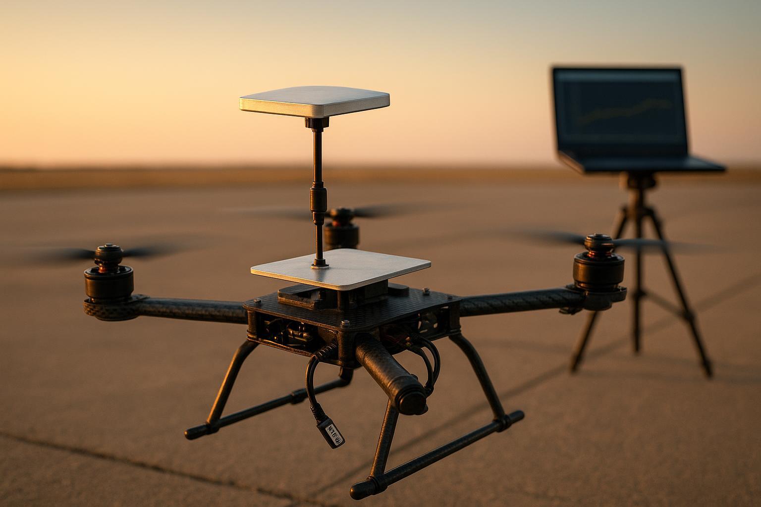
Think of the ground plane as the antenna’s mirror. On composite frames, give the antenna its own mirror: a bonded aluminum plate or a copper‑clad PCB with via stitching. Typical compact patches are characterized on ~70×70 mm, which I treat as the floor. If you can fit ≥100×100 mm, you’ll usually see cleaner low‑elevation C/N0 and fewer multipath‑driven wobbles; ≈150 mm discs are excellent when they fit the platform. This “local metal sky” advice aligns with vendor docs—for instance, Tallysman and Abracon specify performance on defined ground planes in their datasheets, such as Abracon’s APARC2511X‑SGL2L5 multiband patch characterization.
Mount high with full 360° view, above carbon fiber using insulated standoffs to reduce detuning. Bond the plate to system ground with a short, low‑impedance strap. Keep other antennas out of the antenna’s near field and avoid rotor wash masking the sky.
For wiring discipline, aviation guidance is a great model even if you’re not certifying. FAA AC 20‑138D (airworthiness approval for GNSS) stresses clear sky view, low‑loss coax, and routing away from noise; it also pushes installers to verify performance in situ. You can read the advisory here: FAA AC 20‑138D on GNSS installations (2016).
Cabling and the signal‑chain budget (with a worked example)
Cable and connector losses eat your link margin. You don’t have to over‑engineer it—just budget it.
Receiver Margin = LNA_gain − (Cable_loss + Connector_loss + Filter/Splitter_loss) − Required_margin
Example at L1/L2: Suppose your antenna LNA is 28 dB. You run 0.2 m of LMR‑200 (~0.26 dB/m at 1.575 GHz), two SMA pairs (~0.2 dB total typical), and a small in‑line filter (0.5 dB). With a 2 dB required margin:
-
Cable_loss ≈ 0.2 m × 0.26 dB/m = 0.05 dB
-
Total passive loss ≈ 0.05 + 0.2 + 0.5 = 0.75 dB
-
Receiver Margin ≈ 28 − 0.75 − 2 = 25.25 dB (healthy)
If the same run used 0.5 m RG‑316 (~0.88 dB/m at L1): cable loss alone jumps to ~0.44 dB—still fine here, but it adds up quickly on longer runs. Manufacturer data for common UAV cables: Times Microwave lists LMR‑200 at ~0.26 dB/m at 1.575 GHz in the LMR‑200 datasheet. Representative coax comparison tables (for planning, not certification) are summarized by reputable compilers like Universal Radio’s chart.
Two practical rules I’ve adopted: keep the coax short, and minimize adapters. When longer runs are unavoidable, step up to LMR‑200/240‑class cable rather than thin RG‑316.
Element | Typical value at L1 (1.575 GHz) | Notes |
|---|---|---|
Antenna LNA gain | 26–35 dB | From antenna datasheet |
Cable loss (LMR‑200) | ~0.26 dB/m | Manufacturer spec |
Cable loss (LMR‑240) | ~0.21 dB/m | Manufacturer/compiled charts |
Cable loss (RG‑316) | ~0.88 dB/m | Vendor datasheets/compiled charts |
Connector pair (SMA) | 0.05–0.15 dB | Check your exact connector vendor |
In‑line filter/splitter | 0.3–1.0 dB | From device datasheet |
EMI and coexistence: a simple test recipe
On small airframes, the GNSS front end shares space with noisy neighbors: ESCs, DC/DC converters, video downlinks, and LTE/5G modems. Start by identifying emitters (high‑power TX, high di/dt power electronics) and victims (GNSS antenna/coax and receiver). Separate where you can; when you can’t, cross at right angles and avoid long parallel runs. Use double‑shielded coax and bond metalwork properly. FAA AC 20‑190 on aircraft EMC (2023) recommends using recognized EMC installation practices (SAE ARP 60493 / EUROCAE ED‑248) and a risk‑based verification approach. For a feel of the RF cleanliness expected around GNSS, RTCA DO‑160 Section 21/20 set emission and susceptibility expectations for airborne gear; see an accessible summary of Section 21 categories at Keystone’s DO‑160 overview.
My quick validation loop is simple: collect a C/N0 baseline with all radios off; bring subsystems online one at a time and log the deltas. If C/N0 drops several dB when the video link lights up, fix the layout (distance, shielding, ferrites) and re‑test. Spectrum snapshots near L1/L2/L5 taken on the airframe are invaluable for finding spurs.
Validation protocol and acceptance thresholds
Bench first, then fly. I define acceptance thresholds before installation to avoid “it feels better” bias. On a mapping multirotor, I typically expect:
-
TTFx (cold start to RTK fix) within ~15–20 s in a clear field with corrections available.
-
Median C/N0 that meets or exceeds your receiver’s integration benchmarks on open sky, with the 10th percentile staying above the “red zone” even during yaw/roll.
-
Fix ratio above 95% for a 15–20 minute survey profile in open terrain; exercise forward/side slip and proximity to reflective structures for realism.
-
Cycle‑slip counts that don’t explode during turns or low‑elevation tracking.
Log raw observables and receiver reports so you can audit after the flight. Configure elevation masks and constellation use to match your site and mission.
A/B field scenario: 3.5 kg quadrotor mapping UAV
Here’s a representative comparison from my logs on a carbon‑fiber quad.
-
Setup A: L1/L2 patch on a 60×60 mm aluminum plate, 35 cm RG‑316, antenna within 8 cm of an LTE modem, carbon‑fiber top plate immediately below.
-
Setup B: L1/L2/L5 survey patch on a 100×100 mm aluminum plate, 20 cm low‑loss coax (LMR‑200‑class), LTE modem relocated to the opposite boom, ferrites on ESC leads, a short bonding strap to the plate, and a 10 cm standoff above the CF deck.
Observed (environment‑dependent) deltas across several flights: median C/N0 improved by ~3–5 dB‑Hz, time‑to‑RTK‑fix dropped from ~45–60 s to ~10–15 s, fix‑hold survived aggressive forward and side‑slip, and cycle‑slip spikes near building edges were rarer. Your numbers will vary with sky view and EMI, but the pattern—bigger, better ground plane plus cleaner siting and cabling—repeats across platforms.
Neutral example for context: On a composite VTOL where we needed a low‑profile unit, a survey‑grade L1/L2/L5 patch from GNSource was mounted on a 100×100 mm aluminum plate with a 20 cm LMR‑200‑class coax. The integration followed the same bonding and separation rules above; the receiver was configured to use all supported constellations and bands. No certification claims are implied; the example is provided to illustrate a workable integration pattern.
Common engineering mistakes I still see
-
Mounting a high‑grade RTK antenna directly on carbon fiber without a dedicated metal or copper‑clad PCB ground plane, then blaming the receiver for weak C/N0 and unstable fixes.
-
Running long RG‑316 with several adapters because “it was on hand,” burning margin that the LNA needed to overcome.
-
Parking the antenna next to an LTE/video TX or routing GNSS coax alongside power harnesses; emissions and coupling drag down C/N0 and increase cycle slips.
Practical installation checklist (use before the first flight)
-
Ground plane: Metal or copper‑clad PCB, ≥100×100 mm when possible (70×70 mm absolute floor), bonded to system ground via a short strap; mounted on insulated standoffs above composite.
-
Siting and routing: Highest practical location with 360° sky view; separate from transmitters and high‑di/dt power; cross at 90°, secure coax, minimize adapters; keep coax short and prefer LMR‑200/240‑class when >0.3 m.
-
Receiver and firmware: Enable all supported constellations and bands; verify correction service compatibility; set elevation masks; log raw observables; define acceptance thresholds and capture C/N0/TTFx/fix ratio in a baseline open‑field test.
Key takeaways
-
The biggest RTK gains usually come from integration, not swapping receivers: a well‑sized ground plane, clean siting, and disciplined cabling routinely add several dB‑Hz to C/N0 and stabilize ambiguity resolution.
-
Multi‑band, multi‑constellation capability in the UAV GNSS antenna and receiver shortens convergence and improves resilience, but only if the airframe gives the RF front end a fair shot.
-
Treat the signal chain like a budget. Keep coax short, minimize adapters, and select cable by attenuation per meter at L1/L2/L5—not by what’s in the drawer.
FAQ
How tall should I mount the antenna above a carbon‑fiber deck?
There’s no single number that fits every airframe, but a short standoff (on the order of several centimeters) with an insulated, bonded ground‑plane plate above the deck consistently reduces detuning and improves C/N0. Validate with on‑airframe C/N0 baselines before and after the change.
Can I rely on the carbon‑fiber plate as a ground plane?
No. Carbon fiber is conductive but anisotropic and lossy. It does not behave like a continuous RF ground. Give the antenna its own metal or copper‑clad PCB ground plane and bond it properly. Vendors characterize patches on defined plates for a reason.
Is L1‑only viable for RTK on small drones?
It can work in controlled conditions, but dual‑frequency (L1/L2 or L1/L5) significantly improves convergence and fix‑hold, especially under dynamics or partial masking. When your receiver and corrections support it, multiband is worth the SWaP.
How long can my coax be?
Longer than you think—as long as the loss budget closes—but shorter is always better. Compute losses at each band. If you must run longer, move to lower‑loss cable (LMR‑200/240 class) and reduce mated pairs.
What standards should I be aware of if I’m aiming for aviation‑grade discipline?
Use FAA guidance as your north star: installation practices in AC 20‑138D and EMC expectations in AC 20‑190. For context on RF emissions and susceptibility categories near GPS antennas, DO‑160 Section 21/20 summaries like this overview are useful.
Author’s note: The guidance above is based on repeated field integrations and flight tests across multirotor and VTOL platforms, combined with installation and standards documents linked inline. Distribute this checklist to your team, run the baseline tests, and let the data tell you what to fix first.