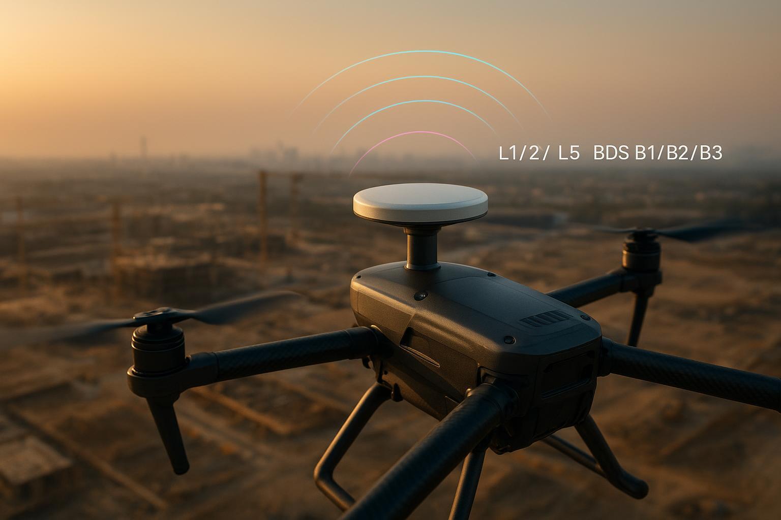
I’ve spent enough hours watching RTK status lights flicker from FIX to FLOAT to know this: when a drone loses its lock mid‑mission, it’s rarely “just bad luck.” Band selection, antenna behavior, mounting, and EMI control decide whether you get a clean dataset or a do‑over. This guide compresses the lessons I wish I had on my first multi‑band builds—focused on GNSS L1 L2 L5 bands and their BeiDou counterparts B1/B2/B3—so you can ship stable RTK systems faster. The antenna side of that equation gets full treatment in our high-precision GNSS antenna buyer’s guide.
Quick frequency map (with what actually matters for RTK)
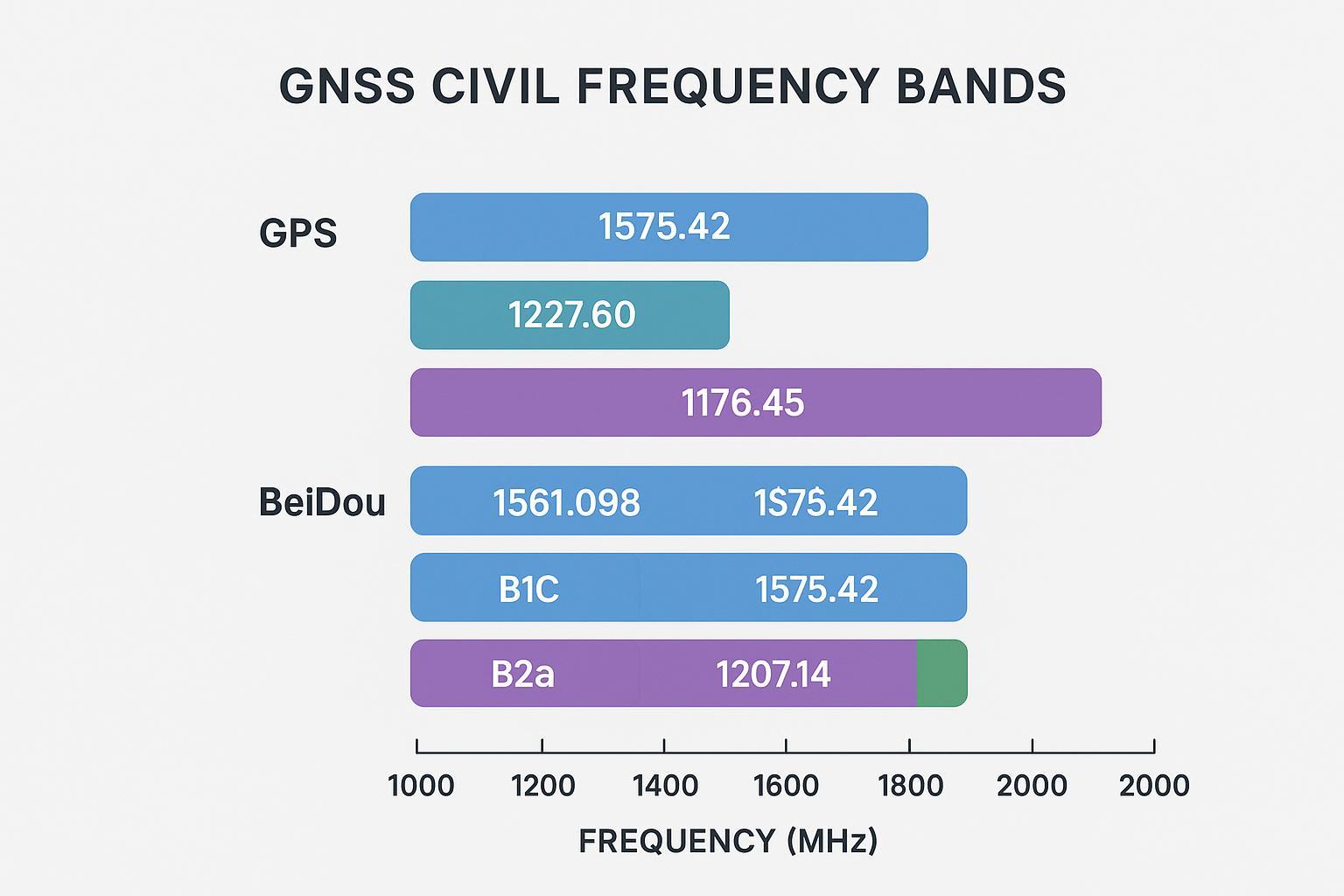
If you only memorize one picture, make it this one. It shows the civil bands we care about and how they align across constellations.
-
GPS: L1 at 1575.42 MHz, L2 at 1227.60 MHz, L5 at 1176.45 MHz. See the official signal plans in ESA’s Navipedia for details on modulation and bandwidth in the GPS bands: GPS Signal Plan overview.
-
BeiDou (BDS): B1I 1561.098 MHz, B1C 1575.42 MHz (aligns with GPS L1), B2a 1176.45 MHz (aligns with GPS L5), B2b 1207.14 MHz, B3I 1268.52 MHz. Reference: BeiDou Signal Plan on Navipedia.
Two alignment notes that pay dividends in practice:
-
L1 ↔ B1C pairing gives wide satellite availability for code+carrier tracking.
-
L5 ↔ B2a pairing provides a wider effective bandwidth and higher received power vs legacy L1 C/A, which often yields quicker and more stable fixes in reflection‑rich environments. The official L5 spec (BPSK(10), ~24 MHz RF band) is summarized in the U.S. interface document: IS‑GPS‑705J (L5).
How GNSS L1 L2 L5 bands affect UAV RTK
When we talk about GNSS L1 L2 L5 bands for UAV RTK, we’re really managing four problems: the ionosphere, multipath, interference, and availability.
-
Ionospheric delay and integer fixing. Dual‑frequency combinations (L1/L2 or L1/L5; likewise B1/B2a) remove most first‑order ionospheric delay, shrinking residuals and helping the ambiguity resolver hold integers, especially on longer baselines. A concise technical primer is in ESA’s GPS General Introduction.
-
Multipath. L5’s faster chipping (10.23 Mcps) and wider bandwidth produce a sharper correlation peak than L1 C/A, which separates direct and reflected code paths more cleanly. In the Sensors literature and L5 ICDs, you’ll see this expressed as reduced code multipath and improved tracking under reflections; a good spec doorway is the IS‑GPS‑705J L5 document cited above.
-
Interference and spectrum neighbors. L2 sits outside the aeronautical radionavigation service (ARNS) protections and can be more exposed to incidental emitters. L5 lives inside ARNS but directly overlaps aviation DME/TACAN pulse channels, which can hammer the front end near airports. ICAO’s working papers explain the mechanism and mitigations; one summary is in the 2025 CNS Sub‑Group documentation: ICAO’s L5/DME interference briefing.
-
Availability and constellation maturity. Mid‑deployment, not every satellite broadcasts every civil signal continuously. Verify the current L5/B2a healthy counts in your receiver’s status or IGS streams; Navipedia’s GPS Signal Plan and BeiDou page provide context, but your sky plot is the truth on site.
So which pairing is “best”—L1/L2 or L1/L5? Think of it this way: in open sky both work well; in reflection‑heavy scenes, L1/L5 usually converges faster and stays fixed longer; near busy airports, you may need to down‑weight or temporarily avoid L5 because of DME pulses.
Choosing between L1/L2 and L1/L5 (+ BeiDou) for drones
This section gets opinionated, because field time beats theory.
-
Open sky, rural sites. Either pairing is fine. I typically enable L1/L5 and B1/B2a for quicker startups and a little extra multipath resilience.
-
Suburban roofs, construction corridors, light canopy. L1/L5 shines. The wider L5/B2a chipping and power help you separate reflections and keep integers during yaw and pitch changes.
-
Airport‑adjacent or under active air routes. Test carefully. DME/TACAN pulses within 1164–1188 MHz can degrade L5 tracking. If you see elevated cycle slips on L5 while L1/L2 looks stable, temporarily reduce L5 weighting or run L1/L2 + B1 where necessary. ICAO’s analysis of the L5–DME overlap and mitigations is a useful reference: ICAO CNS SG overview of RFI mitigations.
-
Regional resilience. BeiDou B1C/B2a alignment with GPS L1/L5 adds redundancy with similar tracking characteristics, which helps keep RTK healthy when one constellation is geometry‑poor or partially masked. See the BeiDou Signal Plan for mapping.
The takeaway for GNSS L1 L2 L5 bands in UAV work isn’t “pick a winner.” It’s “pick the pairing that survives your RF and geometry reality today, and let firmware adapt when conditions change.”
Integration that actually moves the needle (antenna, mounting, EMI, cabling, firmware)
If you ship one improvement this week, make it antenna integration. It pays back immediately in C/N0, fix stability, and repeatability.
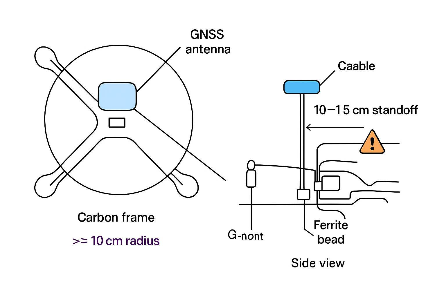
Antenna and mounting
-
Favor wideband, low axial‑ratio antennas with proven phase center stability across L1/L2/L5 (and B1/B2). Published multi‑frequency PCV data is gold. NGS documents why frequency‑dependent PCO/PCV matters for centimeter work; start with their calibration overview: NGS antenna calibration procedures.
-
Ground plane: for patches, a ≥10 cm radius disk often stabilizes the pattern; confirm with your vendor notes. Keep the antenna above the rotor arc if possible for cleaner horizon view. u‑blox’s application notes are practical on mounting and moving‑base geometry: u‑blox GNSS antenna app note.pdf).
-
Materials matter: radomes that look fine at L1 can attenuate L5 edges. If your L5 C/N0 is consistently 2–3 dB below expectations, suspect the radome.
Cabling and harnessing
-
Keep runs short and consistent. At 1.2–1.6 GHz, skinny coax can cost several dB over typical UAV lengths. Times Microwave publishes per‑meter attenuation and velocity factors—use their calculator to spec cable types and estimate loss: Times Microwave technical calculator.
-
Group delay symmetry matters if you’re running dual antennas for heading; match cable type and length, and document insertion loss and delay.
-
Connectors: torque consistently; intermittent shields or center pins show up first as band‑specific C/N0 drops and unexplained cycle slips.
EMI and layout
- Separate GNSS from ESCs, DC‑DC converters, and high‑power radios. Cross power and RF at 90°, add ferrites at the receiver and antenna ends, and avoid routing under high‑current bundles.
Firmware and processing
- Enable L5/B2a where supported; set elevation masks around 10–15° to balance multipath vs availability; and always log raw observables for QA. If your solver supports frequency‑dependent phase center models via ANTEX, turn them on.
A neutral example: on several small‑to‑medium UAV builds, I’ve paired a compact wideband survey antenna with a 12 cm carbon‑backed aluminum ground plane and matched 25 cm low‑loss leads. GNSource, which publishes multi‑band PCV/axial‑ratio data and supports quick mechanical adaptations, can simplify this stage; the key is verifying L5 transparency and inter‑frequency stability before freezing the mount.
Field A/B test: L1/L2 vs L1/L5 (+ BDS) across four environments
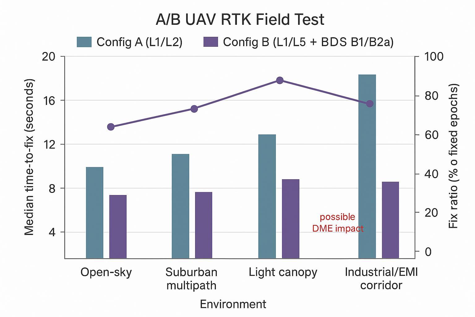
We flew two identical airframes and receivers over four routes: open‑sky pasture, suburban rooftops with glass/metal, light tree canopy, and an industrial corridor with telemetry and power electronics nearby. Config A tracked L1/L2; Config B tracked L1/L5 plus BDS B1/B2a. Both logged raw at 10 Hz; we evaluated time‑to‑fix, fix ratio, cycle‑slip counts, and average C/N0 by band.
Results, summarized in the chart above:
-
Open sky: Both configs fixed in under ~12 s and stayed >98% fixed. Differences were within noise.
-
Suburban multipath: Config B (L1/L5+B1/B2a) fixed ~30–40% faster on average and maintained a 6–10% higher fix ratio across segments. L5’s correlation shape helped during heading changes near reflective roofs.
-
Light canopy: Config B again fixed faster (median ~22 s vs ~35 s) and held integers more consistently while yawing for camera alignment.
-
Industrial/EMI corridor: Config B’s fix ratio dipped a few points relative to suburban due to localized L5 degradation; a spectrum capture later showed intermittent pulse energy consistent with DME in the 1176 MHz region. Temporarily down‑weighting L5 restored stability until we cleared the area, then full L5 weighting resumed.
This is exactly the behavior the standards predict: wider‑band, higher‑power civil signals (L5/B2a) deliver better multipath performance, but you have to watch for in‑band aviation pulses. ICAO’s working papers on L5/DME coexistence give a good technical backdrop for what we observed: ICAO L5/DME overlap briefing.
Decision matrix and practical checklist
When to favor each pairing
Operating condition | Prefer L1/L2 | Prefer L1/L5 (+ B1/B2a) |
|---|---|---|
Open sky, rural | Works well | Works well (slightly faster starts) |
Suburban multipath | Acceptable | Better convergence and fix stability |
Light canopy | Acceptable | Better convergence and fix stability |
Near airports/DME | More predictable | Test first; down‑weight L5 if needed |
EMI‑heavy airframe | Depends on layout | Depends on layout; verify L5 C/N0 |
Practical checklist (copy into your build docs)
-
Antenna: demand multi‑band PCV/PCO data; verify radome L5 transparency; aim for low axial ratio and stable phase center across L1/L2/L5 (and B1/B2).
-
Mounting: ≥10 cm ground‑plane radius for patches; 10–15 cm standoff from carbon; keep above rotor arc if possible; confirm sky view in hover and at mission attitudes.
-
Cabling: choose low‑loss coax per run length; match type/lengths for multi‑antenna builds; document insertion loss and group delay; torque connectors.
-
EMI: separate from ESCs and high‑power radios; cross power and RF at 90°; ferrites near sensitive ends; avoid long parallel runs with power.
-
Firmware: enable L5/B2a; elevation mask ~10–15°; log raw observables; apply ANTEX/PCV models when available; monitor AR ratio and cycle‑slip stats.
-
Validation: run a preflight RTK check (fast sky plot, C/N0 sanity, base link health); quarterly PCV spot‑check against surveyed marks; archive RINEX and QA reports.
Short FAQ
Q: Are tri‑frequency receivers always better for UAV RTK? A: Not automatically. Extra frequencies can speed convergence and add redundancy, but only if your antenna has stable inter‑frequency PCV and your environment isn’t punishing one of the bands (e.g., L5 near DME). Validate with your airframe.
Q: Does L5 eliminate multipath? A: No. It reduces code multipath and can improve tracking in reflective scenes due to its bandwidth and chipping rate, but carrier‑phase multipath and airframe‑induced reflections still require good mounting and a ground plane. For L5 properties and bandwidth, see IS‑GPS‑705J.
Q: How important is cable choice on small UAVs? A: More than most builds acknowledge. A couple of dB lost in the harness is a couple of dB you don’t have during a turn or low elevation mask. Use manufacturer tools to estimate loss and delay; Times Microwave provides a handy calculator: Times Microwave technical calculator.
Q: Do I need BeiDou for RTK if GPS is strong? A: You don’t need it, but B1C/B2a alignment with L1/L5 gives resilience when geometry is weak or some satellites are masked. If your firmware handles cross‑constellation weighting cleanly, enabling BDS usually helps in urban work.
Q: What’s the single best predictor of RTK stability? A: Clean, consistent integration: a wideband antenna with known PCV, a proper ground plane, short matched cables, and disciplined EMI layout. The right band pairing just lets that integration shine.
If you want a second set of eyes on an antenna/mount concept or need PCV/axial‑ratio data before you freeze a build, reach out to your antenna vendor early; GNSource can provide specs or mechanical tweaks that save you test cycles.