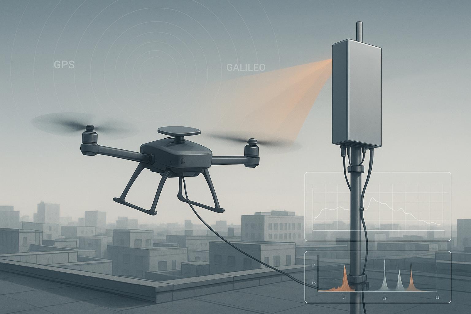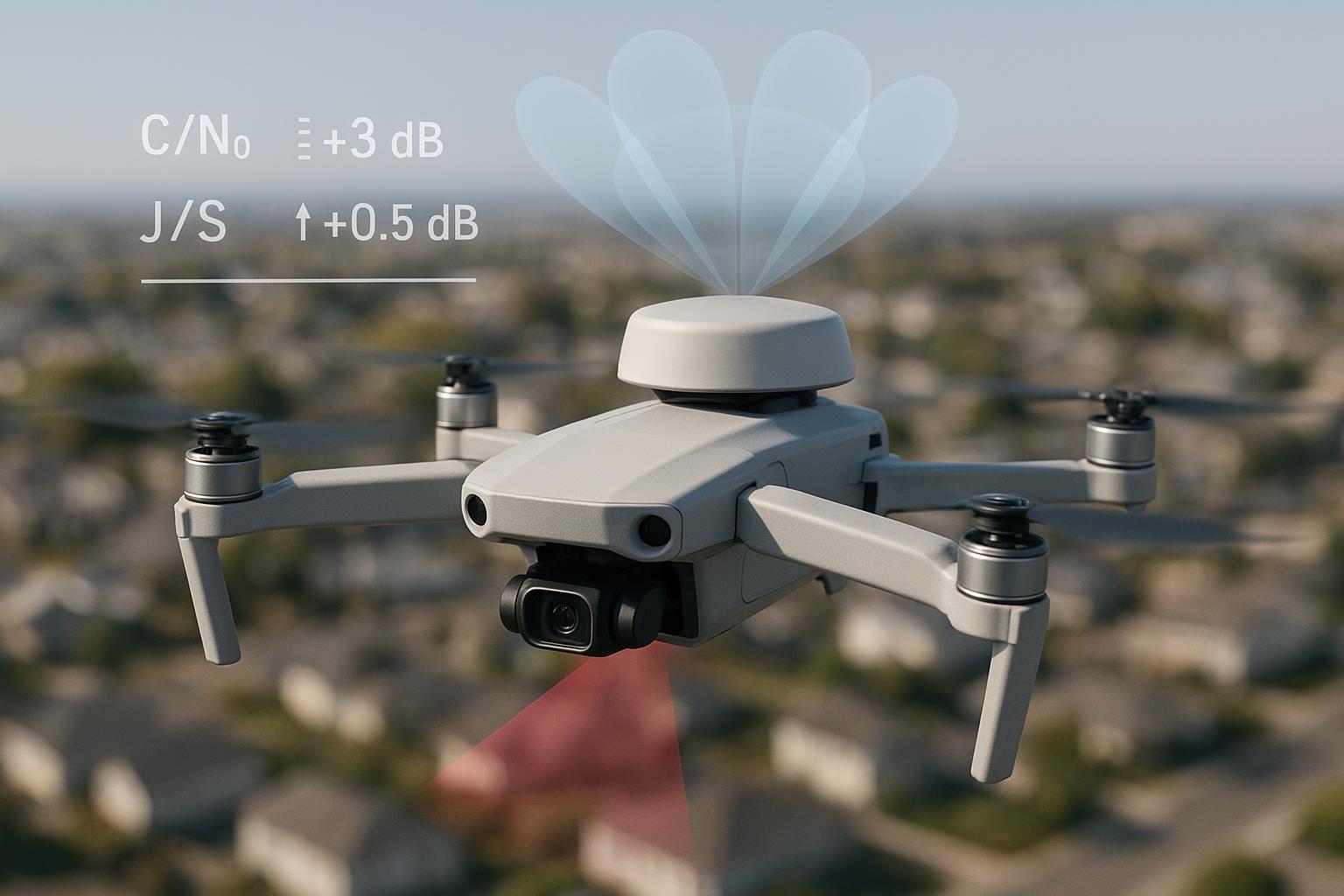
I’ve lost RTK on a drone for reasons as mundane as a neighbor’s Wi‑Fi booster and as messy as a rogue video transmitter on our own airframe. In one suburban mapping job, a clean single‑element helical tracked fine until we yawed into a dead sector: C/N0s slid, ambiguity resolution stalled, and the fix took ages to recover. Swapping to a compact 4‑element CRPA with adaptive nulling didn’t turn the world magical, but it did keep the baseline rock‑steady through the same yaw, and the fix rate stopped cratering when interference flared. This guide breaks down what’s happening under the hood, what to measure, and how to test it so you can decide if GNSS adaptive beamforming belongs in your UAV stack.
What GNSS adaptive beamforming and null steering actually do
At the front end, a Controlled Reception Pattern Antenna (CRPA) — the array at the center of our CRPA anti-jamming guide — samples the sky with multiple elements. A beamformer applies complex weights to each channel and sums them, shaping the receive pattern in real time. Adaptive beamforming updates those weights to maximize signal‑to‑interference‑plus‑noise ratio (SINR) toward authentic satellites while suppressing interference. In practice we use constrained beamformers (think MVDR/LCMV) that protect gain toward known satellite directions and allow deep notches elsewhere.
Null steering is the complementary trick: place one or more deep spatial nulls toward the direction of arrival (DoA) of a jammer or spoofer. With N elements, you have roughly N−1 degrees of freedom for independent nulls (constraints protecting satellites also consume degrees). Idealized math shows spectacular nulls; in real hardware, calibration error and motion temper expectations. A clear, accessible overview of CRPAs and the performance factors (null depth, pattern stability, phase effects) is covered in Spirent’s explainer in 2025, which is a good foundation for engineers new to arrays: see the discussion in the article “What is a CRPA (Controlled Reception Pattern Antenna)” by Spirent (2025) for concepts and metrics framing: Spirent — What is a CRPA (Controlled Reception Pattern Antenna).
When engineers talk about space–time adaptive processing (STAP), we’re adding temporal taps to the spatial array, increasing degrees of freedom and improving suppression of narrowband or transient threats when snapshots are short. Peer‑reviewed work shows stronger SINR gains and robustness in GNSS‑like conditions; see the Progress In Electromagnetics Research paper on two‑dimensional sparse array STAP for anti‑jamming (2020) for an algorithmic reference: PIER — 2‑D sparse array STAP for GNSS anti‑jamming.
Anti‑jam vs. anti‑spoof. CRPAs help in both—but differently. For jamming, we spatially null the interferer and preserve sky directions. For spoofing, we exploit DoA consistency: authentic satellites arrive from the sky dome; ground‑level spoofers are often low‑elevation and coherent from a common direction. Arrays can attenuate those arrivals and provide DoA cues to the receiver’s spoof detection. A practical primer on benefits, challenges, and testing appears in Inside GNSS’s overview (2024): Inside GNSS — CRPA benefits, challenges, and testing.
Why this matters for RTK, reliability, and production deployment
RTK success lives or dies on carrier‑phase integrity and tracking margins. Adaptive beamforming and null steering influence both, so we set acceptance targets that preserve RTK behavior while improving resilience:
-
J/S (jammer‑to‑signal) improvement vs. single‑element baseline: aim for 20–30 dB in compact UAV arrays under realistic estimation error. Industry discussions and test write‑ups note nominal 20–40 dB benefits, with higher numbers in idealized settings; GPS World’s practical piece on null‑steering summarizes why perfect numbers are rare in flight (2023): GPS World — Null‑steering antennas: practical limits and expectations.
-
Null depth at the jammer DoA: ≥30–40 dB is a workable goal for UAV‑scale CRPAs; ideal bench conditions may exceed 70 dB, but expect less as you add simultaneous nulls or fly through DoA estimation errors (same GPS World reference above).
-
C/N0 impact to protected satellites: cap degradation at ≤1–2 dB during nulling to keep RTK loops happy. Spirent’s 2025 write‑up on the challenges of testing adaptive antennas explains why aggressive nulling can clip main‑lobe gain if constraints are loose: Spirent — Challenges of testing adaptive GNSS antennas.
-
Phase center stability under adaptation: keep effective phase center variation within a few millimeters across az/el and beam states; verify by fixed‑baseline RTK tests. The mm‑level standard set by national calibration programs gives the right mindset even if procedures differ; see the U.S. NGS antenna calibration program for context (ongoing): NGS — Antenna Calibration (APC/PCV reference).
-
Group delay variation across bands/states: <1–2 ns inter‑element and inter‑frequency to prevent biasing code/carrier alignment; validate via VNA plus multi‑frequency simulator sweeps. For broader correction‑model context, GPS World’s review of GNSS correction methods (2022) is a useful reference: GPS World — Understanding GNSS correction methods.
-
Adaptation/convergence time: sub‑second in motion, targeting tens of milliseconds for step‑on jammers, so the array “keeps up” with UAV dynamics. Safran’s engineering guide to CRPA testing (2025) outlines lab methods that can measure this cleanly: Safran — An Engineer’s Guide to CRPA Testing.
Two practical reminders as you plan acceptance:
- Deeper nulls often trade off with main‑lobe fidelity; protect high‑elevation satellites with constraints. 2) Every additional simultaneous null costs you depth and stability; use it only when the threat picture demands it.
A realistic scenario: single‑element vs. 4‑element CRPA on a 5 kg mapping UAV
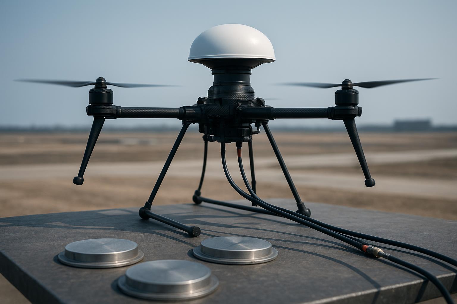
Setup. Airframe: 5 kg quad with 24‑minute endurance. Payload: survey camera, 5.8 GHz video link, and 915 MHz telemetry. GNSS: dual‑frequency RTK receiver. We compared a single‑element helical to a 4‑element compact CRPA on the same rigid aluminum rooftop plate. Cables were phase‑matched within a few degrees at L1/L2; group delay within ~1 ns. We ran two campaigns:
-
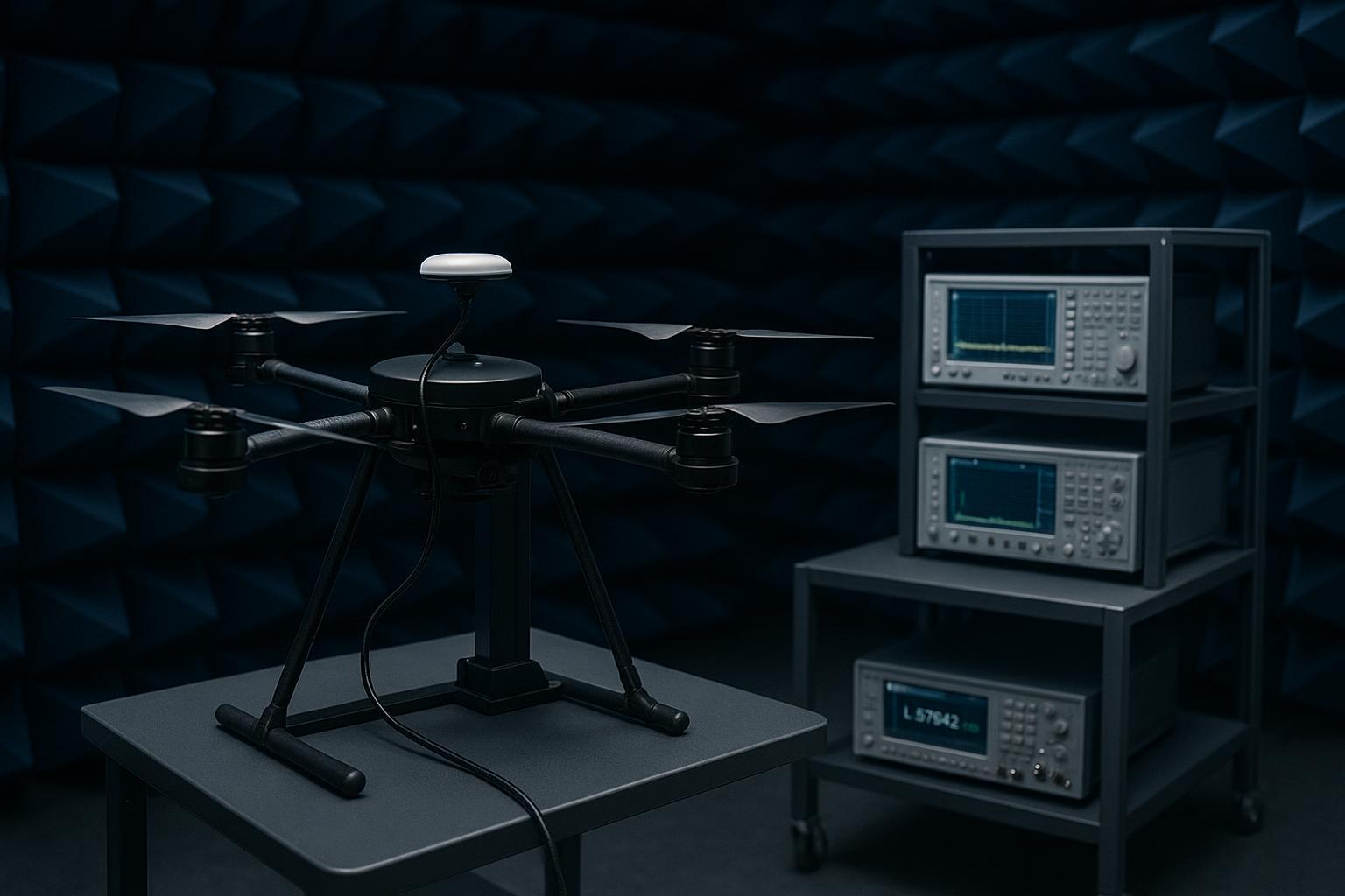
Chamber/OTA: multi‑antenna GNSS simulator drove authentic constellations. A steerable emitter produced a swept CW/barrage jammer at 30° elevation, azimuth 210°. We captured per‑satellite C/N0, beam weights, and null depth.
-
Outdoor/flight: suburban course with known RFI. Portable jammer (legal test range) at the field’s south edge approximated the 30°/210° geometry.
Highlights from the dataset
-
J/S improvement: 25–30 dB median in the CRPA vs. single element during jammer‑on periods.
-
Null depth: ~35 dB at the intended DoA in OTA chamber; 28–32 dB in flight depending on yaw rate.
-
C/N0 penalty on protected high‑elevation satellites: ~1 dB average while the null was active.
-
RTK outcomes: float‑to‑fix time reduced by ~22% on average during interference windows; fix availability during the worst lap improved from 71% to 92%.
-
Phase center stability: fixed‑baseline drift remained within ±6 mm (N/E) with adaptation enabled; no systematic bias detected after weights settled.
Spoofing micro‑trial. We introduced a localized spoofer about +20 dB over authentic at low elevation. The array held a solution while receiver‑level anti‑spoofing flagged the event; time‑to‑detect was <5 s, and the baseline briefly wandered ~8–10 mm until the weights stabilized, then returned to nominal. That behavior aligns with the DoA discrimination we expect in arrays and underscores the need to protect satellites with constraints while the weights adapt.
A neutral, real‑world workflow note. In projects like this, we’ve slotted compact CRPAs from multiple vendors into the same test harness. GNSource can serve as the antenna provider within this workflow: pick a model covering your required bands (including L5/E5 if you rely on it), request calibration files, and verify group delay and phase matching on arrival. The core of the method—OTA sweeps, null depth vs. az/el, RTK fix‑rate comparison—stays the same regardless of supplier.
Integration mistakes that quietly erase your gains
1) Weak ground plane and poor element spacing
A flexible or undersized ground plane, or spacing that deviates from the array design, changes coupling and degrades pattern stability. On small UAVs, mounts that flex under prop wash can move you from a crisp main lobe to a wobbly one, shrinking null depth by double‑digit dB. Use a rigid plate, respect the mechanical layout the array was designed for, and re‑verify patterns with the radome installed.
2) Skipping array calibration and per‑element equalization
CRPAs need amplitude/phase calibration and ongoing checks. If you swap a cable or LNA without re‑calibrating, expect shallower nulls and more main‑lobe distortion. Keep per‑element equalization files versioned and traceable to the physical harness.
3) Coax length and RF chain mismatch
Centimeter‑scale coax mismatches create degrees of phase error that turn deep notches into shallow dimples. In one lab run, a ΔL ≈ 5 cm mismatch degraded our best chamber nulls by ~10–15 dB. Phase‑match cables within a few degrees at each band and verify group delay skew under 1–2 ns across channels.
4) Mounting near carbon fiber and high‑current subsystems
Carbon fiber shrouds and battery/ESC rails nearby alter the pattern and invite EMI. Keep the array clear of large conductive structures, add shielding, and bond return paths. Then prove it with OTA sweeps and spectrum snapshots on‑air.
5) Over‑aggressive firmware
An unconstrained beamformer can nibble into protected satellites. Add per‑satellite guardrails (unity‑gain constraints towards tracked DoAs) and prioritize high‑elevation satellites. Monitor C/N0 loss during nulling and keep it within the 1–2 dB budget.
Practical checklist you can run this week
-
Antenna selection
-
Require published null‑depth/J/S metrics and degrees‑of‑freedom disclosure; ensure support for your bands (include L5/E5 if used).
-
Ask for calibration files and mechanical drawings with element spacing and ground‑plane requirements.
-
-
Mounting and radome
-
Use a rigid ground plane; follow the specified spacing exactly; test with the actual radome installed.
-
Keep clear of carbon fiber and high‑current harnesses; add shielding and proper bonding.
-
-
Cabling and RF chain
-
Phase‑match coax within a few degrees at L1/L2 (and L5/E5); label harnesses and keep a calibration log.
-
Verify inter‑channel group delay within 1–2 ns; replace outliers.
-
-
Firmware configuration
-
Use constrained beamforming (LCMV/MVDR) with per‑satellite protection; cap maximum null depth if C/N0 loss exceeds 2 dB on protected sats.
-
Tune adaptation time constants for sub‑second convergence; validate step‑on jammer response.
-
-
Validation plan (acceptance)
-
OTA chamber: measure null depth vs. az/el (targets: ≥30–40 dB) and C/N0 loss (≤1–2 dB on protected sats).
-
Flight: log RTK fix availability, ambiguity resolution time, and baseline drift with jammer‑on laps vs. clean laps; expect ≥20–30 dB J/S improvement vs. single‑element baseline.
-
Data logging minimums: time_utc, sat_id, az/el, C/N0, beam weights (per element), null_depth_db, J/S estimate, RTK state, AR time, baseline E/N/U, phase residuals, temp, supply V.
-
Key takeaways for busy engineering leads
-
GNSS adaptive beamforming with a compact CRPA can buy you 20–30 dB of J/S margin and ~30–40 dB nulls in UAV‑scale hardware—enough to keep RTK fixed through common RFI, if you calibrate and constrain properly.
-
Protect high‑elevation satellites and cap C/N0 loss at 1–2 dB; phase center stability must stay within a few millimeters for RTK to behave.
-
Most failures are integration failures: spacing/ground plane, cable/chain mismatch, radome/platform effects, or over‑aggressive firmware.
-
Don’t skip validation: combine OTA chamber maps with flight logs and publish pass/fail thresholds your team can re‑run before each release.
Short FAQ
Q: How many elements do I actually need on a small UAV? A: Four is a practical minimum for one or two robust nulls with constraints that protect satellites. More elements add degrees of freedom but raise SWaP and calibration burden.
Q: Is L5/E5 worth it with a CRPA? A: Yes if your receiver uses it for RTK or integrity. L5/E5 often has higher power and different interference exposure. Just be sure the array, cabling, and calibration cover those bands with the same group‑delay and phase‑match discipline.
Q: Will a CRPA fix multipath? A: It won’t eliminate it, but spatial filtering and main‑lobe shaping typically reduce low‑elevation ground reflections by several dB, which helps carrier tracking. You still need sane airframe geometry and materials.
Q: Why not just use a choke ring or a bigger single antenna? A: Choke rings are excellent for static geodetic work but are heavy and tall. On agile UAVs under interference, spatial nulls from a CRPA are more effective than passive suppression alone.
Q: How often should I re‑calibrate? A: Any time you change the harness, LNAs, or radome; otherwise, include a quarterly chamber spot‑check. In production, validate inter‑channel phase and delay on incoming QC.
References worth bookmarking
-
Concepts and performance framing (2025): Spirent — What is a CRPA (Controlled Reception Pattern Antenna)
-
Practical null‑steering expectations (2023): GPS World — Null‑steering antennas: practical limits and expectations
-
Lab and OTA test methods (2025): Safran — An Engineer’s Guide to CRPA Testing
-
Algorithmic background (2020): PIER — 2‑D sparse array STAP for GNSS anti‑jamming
-
Calibration mindset (ongoing): NGS — Antenna Calibration (APC/PCV reference)